OUCG8D-440H-AKeyless Entry System (Transmitter)
NIDEC MOBILITY CORPORATION
Click to zoom
Application Details
- Equipment Class
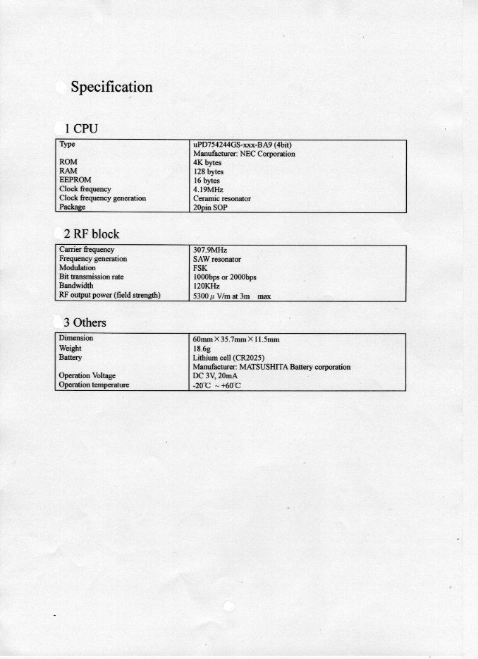
- DSC - Part 15 Security/Remote Control Transmitter
- Date of Grant
- Oct 31, 2000
- Application Purpose
- Original Equipment
- Date of Application
- May 23, 2000
- Equipment Note
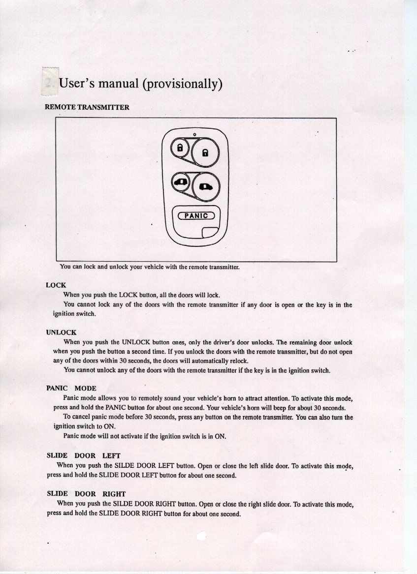
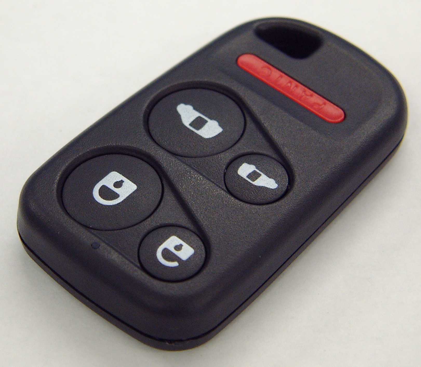
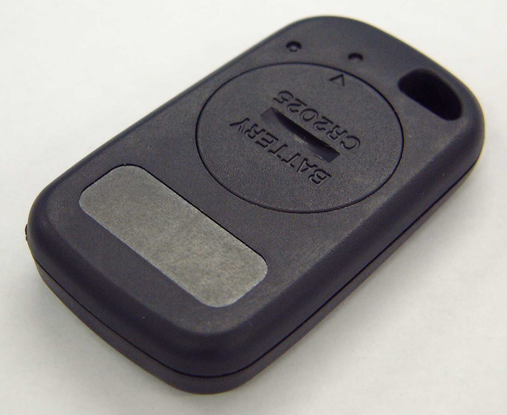
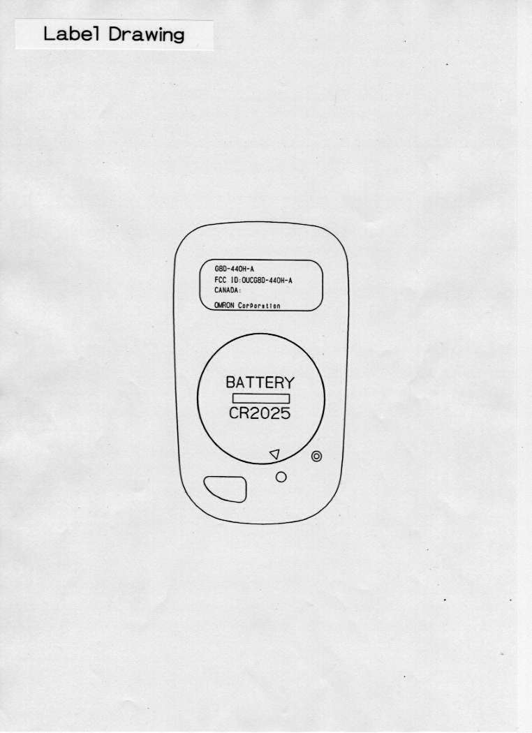
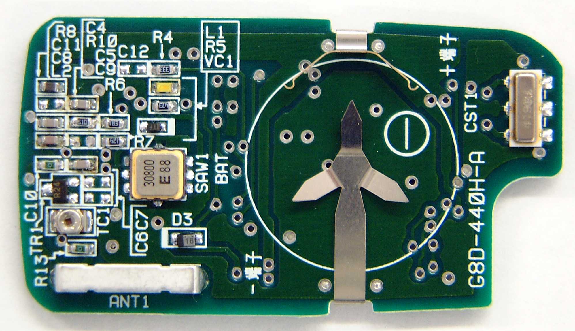
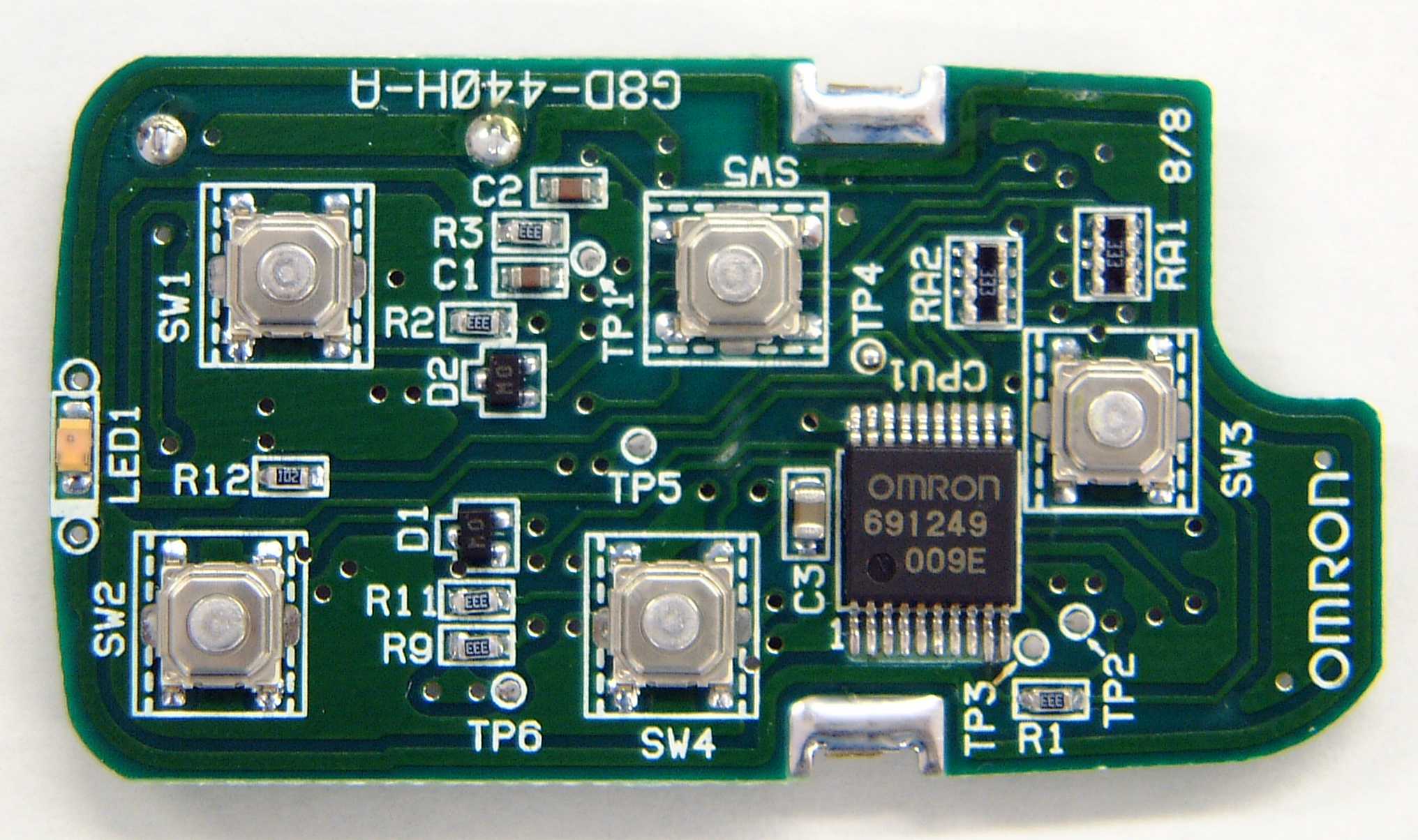
- Keyless Entry System (Transmitter)
- Frequency Range
- 307.90000000 - 307.90000000
- Company
- NIDEC MOBILITY CORPORATION
- Country
- Japan
Documents & Files
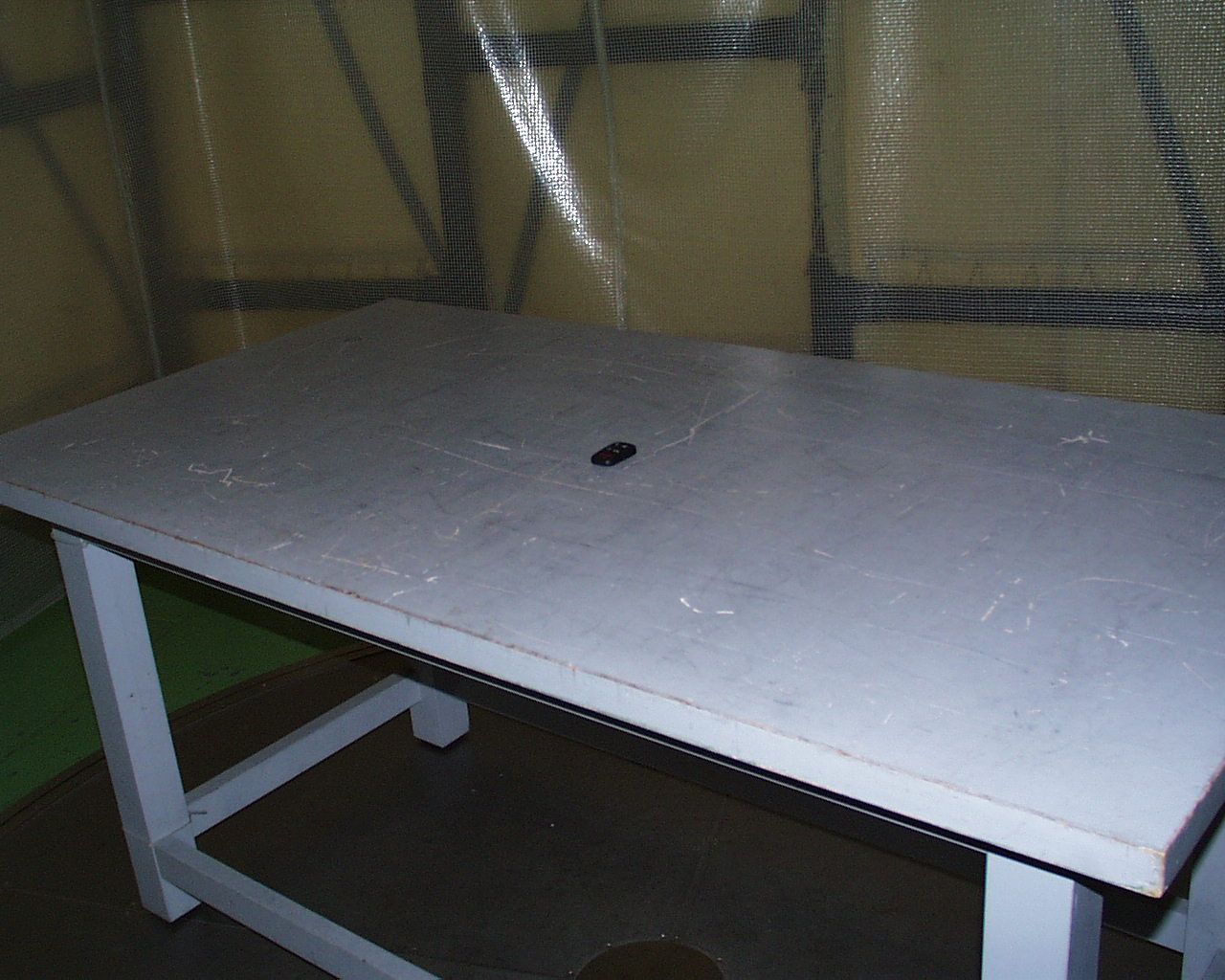
Document Text
Text extracted from the exhibit documents filed with the FCC. Open a document above to read the original.
Test Report
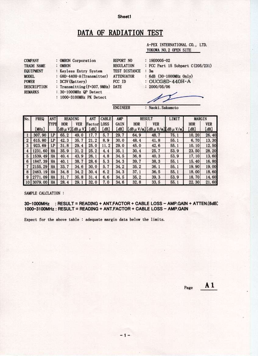
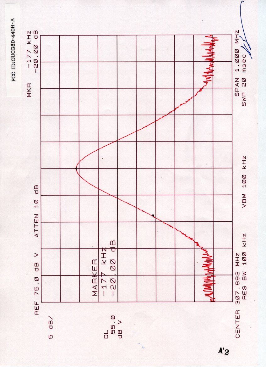
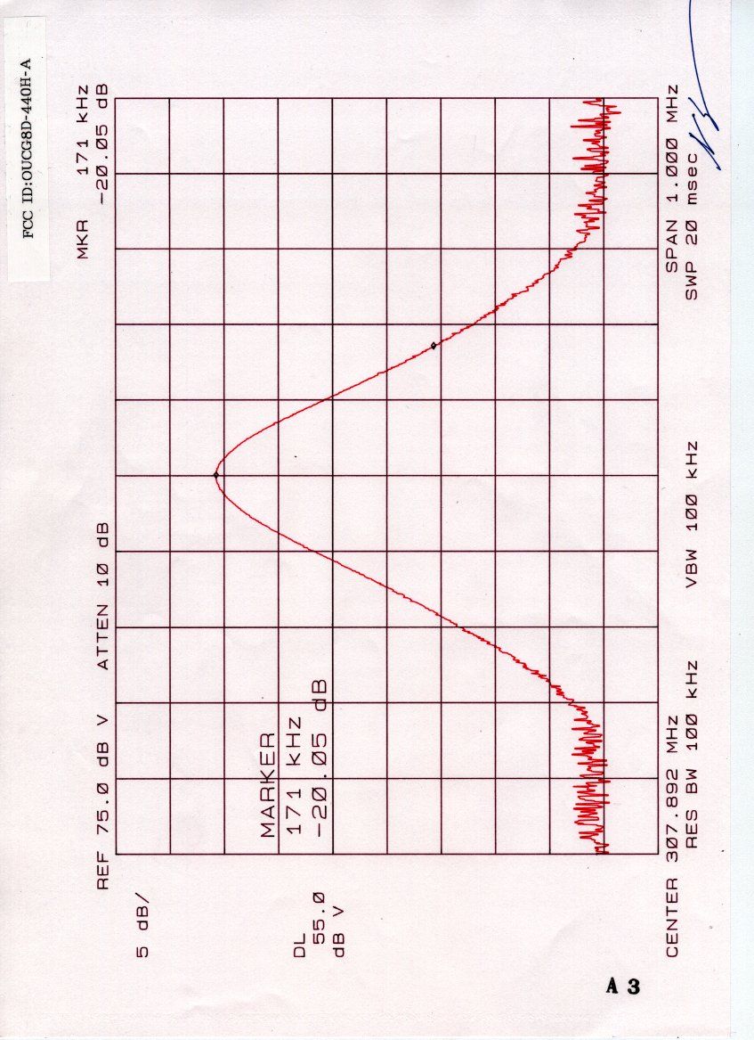
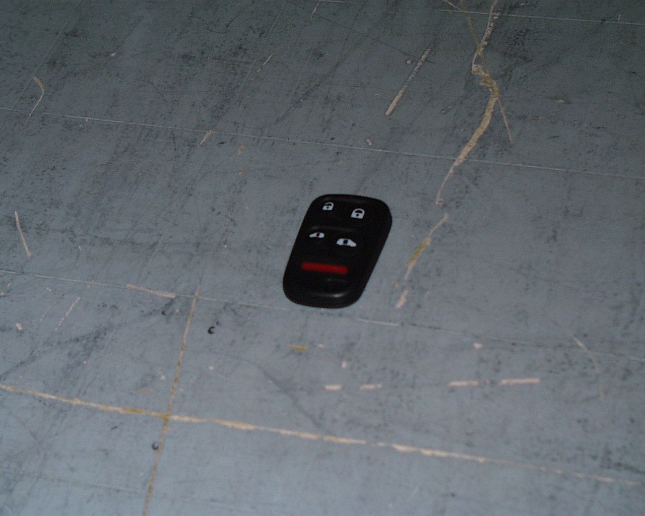
FCC ID : OUCG8D-440H-A Our reference : 19E0005-02 Page: 2 of 13 Issued date: 2000-5-8 Testing Laboratory A-pex International Co., Ltd. Telephone:+81 596 39 1485 Table of Contents Page 1 GENERAL INFORMATION3 1.1 Tested Methodology4 1.2 Test Facility4 2 PRODUCT DESCRIPTION5 3 TESTED SYSTEM DETAILS5 4 SYSTEM TEST CONFIGURATION6 4.1 Justification6 4.2 Test Procedure6 Figure 4.2 Configuration of Tested System7 5 RADIATED MEASUREMENT PHOTOS8 Figure 5.1 Radiated Measurement Photos8 5.1 Measurement Uncertainty9 6 RADIATED EMISSION DATA10 6.1 Field Strength Calculation11 7 TEST EQUIPMENT USED12 APPENDIX13 Test Data A1 - A3 FCC ID : OUCG8D-440H-A Our reference : 19E0005-02 Page: 3 of 13 Issued date: 2000-5-8 Testing Laboratory A-pex International Co., Ltd. Telephone:+81 596 39 1485 1 GENERAL INFORMATION APPLICANT: OMRON Corporation ADDRESS: 1-501, Yashirogaoka, Meito-ku, Nagoya-city Aichi, 465-0051 Japan Tel: +81-52-704-2525 Fax: +81-52-704-2769 REGULATION(S): FCC Part 15 Subpart C MODEL NUMBER: G8D-440H-A SERIAL NUMBER: - KIND OF EQUIPMENT: Keyless Entry System (Transmitter) TESTED DATE: May 6, 2000 RECEIPT DATE OF SAMPLE : April 28, 2000 REPORT FILE NUMBER: 19E0005-02 TEST SITE: A-PEX Yokowa NO.2 Open Test Site FCC ID : OUCG8D-440H-A Our reference : 19E0005-02 Page: 4 of 13 Issued date: 2000-5-8 Testing Laboratory A-pex International Co., Ltd. Telephone:+81 596 39 1485 1.1 Tested Methodology Radiated testing were performed according to the procedures in FCC/ANSI C63.4(1992). Radiated testing was performed at a distance of 3 meters from the antenna to EUT. 1.2 Test Facility The open area site measurement facility used to collect the radiated data is located on 108, Yokowa-cho, Ise-shi, Mie-ken, 516-1106 Japan. This site has been fully described in a report dated May. 27, 1997 submitted to FCC office, and listed dated Aug. 18, 1997 (31040/SIT 1300F2) and accepted Feb. 19, 1998 (IC2973-3) by Industry Canada. FCC ID : OUCG8D-440H-A Our reference : 19E0005-02 Page: 5 of 13 Issued date: 2000-5-8 Testing Laboratory A-pex International Co., Ltd. Telephone:+81 596 39 1485 2 PRODUCT DESCRIPTION OMRON Corporation, Model G8D-440H-A (referred to as the EUT in this report) is a Keyless Entry System (Transmitter). The specification is as following : Operation Frequency: 4.19MHz Carrier Frequency : 307.9MHz Modulation: FSK Operation Voltage: DC 3V, 20mA (Battery) 3 TESTED EQUIPMENT DETAILS The FCC IDs for all equipment, plus description of all cables used in the tested system are: Model FCC ID Description Cable description Backshell Material (1) OMRONOUCG8D-440H-AKeyless Entry System - - M/N: G8D-440H-A (Transmitter) S/N: - (EUT) FCC ID : OUCG8D-440H-A Our reference : 19E0005-02 Page: 6 of 13 Issued date: 2000-5-8 Testing Laboratory A-pex International Co., Ltd. Telephone:+81 596 39 1485 4 SYSTEM TEST CONFIGURATION 4.1 Justification The measurement was performed with the system configuration shown in Figure 4.2. Running mode was taken for the EUT operation mode. 4.2 Test Procedure Tabletop Equipment Radiated Emissions EUT was placed on a platform of nominal size, 1m by 1.0m, raised 80cm above the conducting ground plane. Test was made with the antenna positioned in both the horizontal and vertical planes of polarization. The measurement antenna was varied in height above the conducting ground plane to obtain the maximum signal strength. FCC ID : OUCG8D-440H-A Our reference : 19E0005-02 Page: 7 of 13 Issued date: 2000-5-8 Testing Laboratory A-pex International Co., Ltd. Telephone:+81 596 39 1485 Figure 4.2 Configuration of Tested System Front View (1) Top View (1) FCC ID : OUCG8D-440H-A Our reference : 19E0005-02 Page: 8 of 13 Issued date: 2000-5-8 Testing Laboratory A-pex International Co., Ltd. Telephone:+81 596 39 1485 5 RADIATED MEASUREMENT PHOTOS Figure 5.1 Radiated Measurement Photos FCC ID : OUCG8D-440H-A Our reference : 19E0005-02 Page: 9 of 13 Issued date: 2000-5-8 Testing Laboratory A-pex International Co., Ltd. Telephone:+81 596 39 1485 5.1 Measurement Uncertainty Radiated Emission Test The measurement uncertainty (with a 95% confidence level) for this test was +3.3dB. The data listed in this test report has enough margin, more than 3.3dB. FCC ID : OUCG8D-440H-A Our reference : 19E0005-02 Page: 10 of 13 Issued date: 2000-5-8 Testing Laboratory A-pex International Co., Ltd. Telephone:+81 596 39 1485 6 RADIATED EMISSION DATA The initial step in collecting radiated data was a spectrum analyzer peak scan of the measurement range (30MHz-3100MHz). The final data was reported in the worst-case emissions. The minimum margin to the limit is as follows : * 30MHz - 1000MHz : QP Detect *1000MHz - 3100MHz : PK Detect ReceiverCorrectionField FrequencyReadingFactorStrengthLimitMargin (GHz)(dBuV)(dBuV)(dBuV/m)(dBuV/m)(dBuV) 615.842.3 6.148.4 55.1 6.7 The Fundamental Frequency of this equipment is 307.9MHz. The peak of output level of fundamental frequency was confirmed at the 307.9MHz by perfarming the meaurement. It was corroborated that equipment was within of the tolerance which is prescribed in the FCC requlation Part 15 Subpart C sec. 15.231 (c). Since the fundamental frequency is 307.9MHz, the upper limit could be 308.6 MHz and lower limit could be 307.2MHz. The measurement result was 308.1MHz when the limit was 308.6MHz and also another measurement result was 307.7 MHz when the limit was 307.2MHz. Any spurious emissions did not detect except fundamental frequency’s spurious. FCC ID : OUCG8D-440H-A Our reference : 19E0005-02 Page: 11 of 13 Issued date: 2000-5-8 Testing Laboratory A-pex International Co., Ltd. Telephone:+81 596 39 1485 6.1 Field Strength Calculation The field strength is calculated by adding the Antenna Factor, Cable Factor and Antenna Pad, and subtracting the Amplifier Gain from the measured reading. The sample calculation is as follows : FS = RA + AF + CF + AT - AG where FS = Field Strength RA = Receiver Reading AF = Antenna Factor CF = Cable Factor AT = Antenna Pad AG = Amplifier Gain Assume …
Text truncated - open the document above for the full version.
Contact Information
Applicant
Shinya Takenouchi(Manager)
Technical Contact
A-Pex International Co., Ltd.Naoki Sakamoto
[email protected]+81-596-39-1485
108 Yokowa-cho · Ise-shi Mie-ken · Japan
Non-Technical Contact
A-Pex International Co., Ltd.Momo Tsukamoto
[email protected]+81-596-39-1485
Test Firm
UL Japan, Inc.Kazunori Nishimura
Technical Specifications
| # | Rule Parts | Frequency Range | Power Output |
|---|---|---|---|
| 1 | 15C | 307.9 MHz - 307.9 MHz | - |
Other Applications from NIDEC MOBILITY CORPORATION
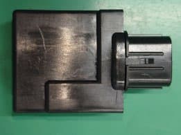
OUCTPMS1R
Jul 02, 2023TPMS ECU
Equipment Class
CYY - Communications Receiver used w/Pt 15 Transmitter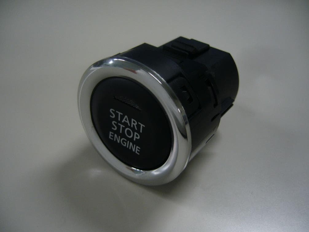
OUCR328E
Nov 29, 2020Transmitter of Keyless Entry System
Equipment Class
DCD - Part 15 Low Power Transmitter Below 1705 kHz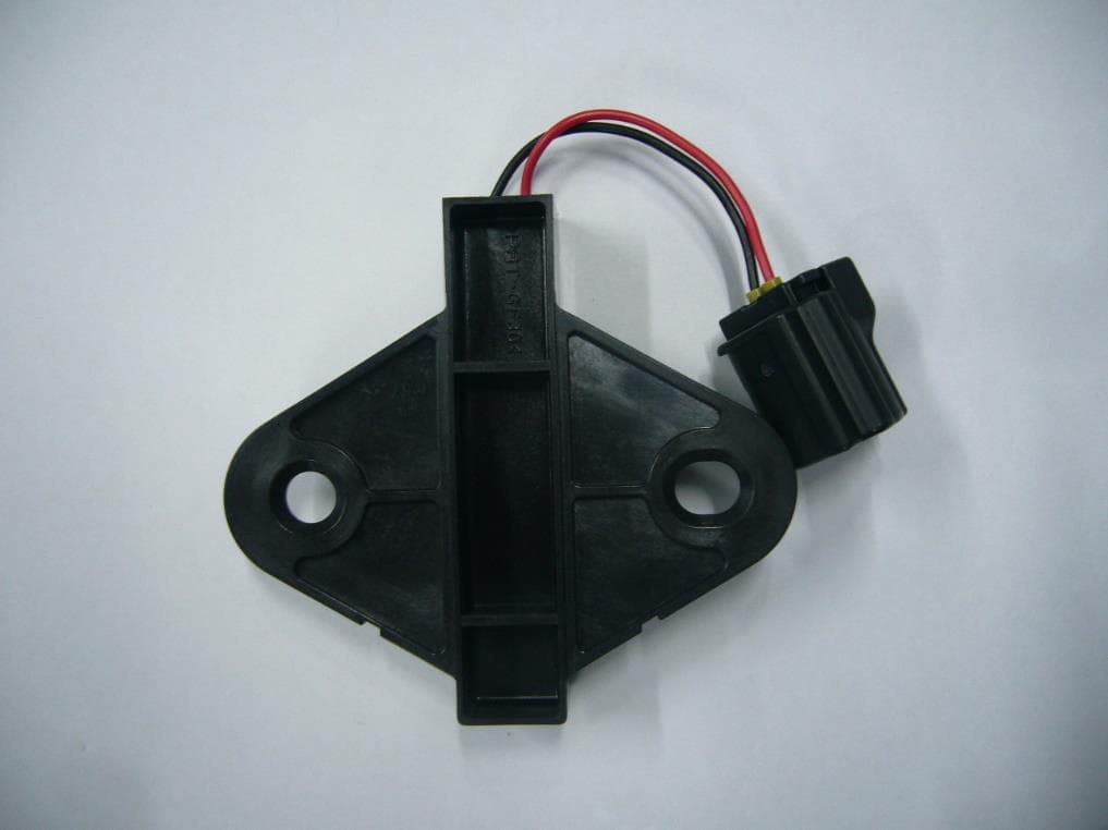
OUCR515E
Nov 29, 2020Transmitter of Keyless Entry System
Equipment Class
DCD - Part 15 Low Power Transmitter Below 1705 kHz
OUC744M-KEY-N
Sep 23, 2020Keyless Operation Key (FOB)
Equipment Class
DSC - Part 15 Security/Remote Control Transmitter
OUCGGM-M018
Aug 04, 2020ETACS
Equipment Class
CYY - Communications Receiver used w/Pt 15 Transmitter