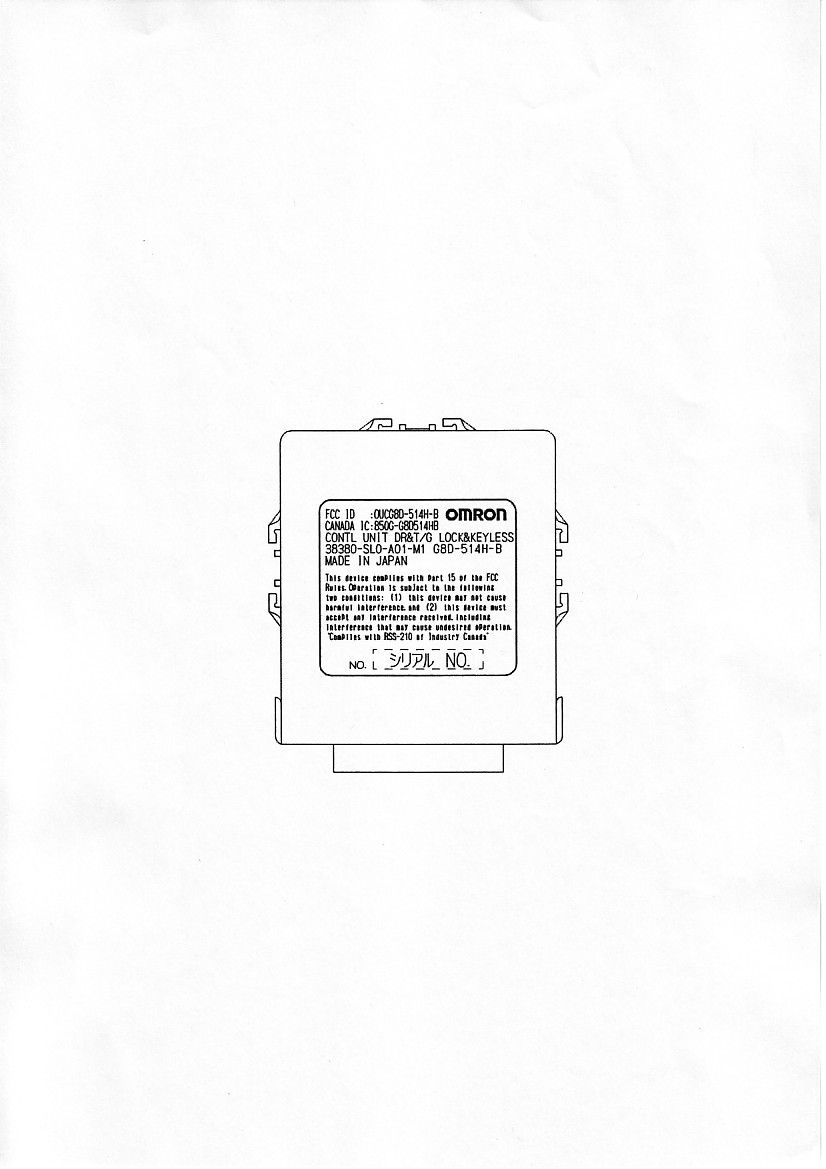
OUCG8D-514H-BKeyless Entry System Receiver
NIDEC MOBILITY CORPORATION
Click to zoom
Application Details
- Equipment Class
- CYY - Communications Receiver used w/Pt 15 Transmitter
- Date of Grant
- Mar 24, 2003
- Application Purpose
- Original Equipment
- Date of Application
- Mar 24, 2003
- Equipment Note
- Keyless Entry System Receiver
- Frequency Range
- 313.85000000 - 313.85000000
- Company
- NIDEC MOBILITY CORPORATION
- Country
- Japan
Documents & Files
Document Text
Text extracted from the exhibit documents filed with the FCC. Open a document above to read the original.
Users Manual
G8D-514H-B Receiver, RF Keyless Entry System Table of contents 1. Constitution of the Radio Frequency Keyless Entry system with Door Lock Controller for vehicle ...................................................................................... 1 2. User’s manual (provisionally) .......................................................................... 2 3. Block diagram ................................................................................................ 3 4. Specification ................................................................................................... 4 5. Features .......................................................................................................... 5 6. PCB ................................................................................................................ 6 6.1 Circuit diagram ........................................................................................... 6 6.2 Parts layout ................................................................................................. 7 6.3 Pattern layout .............................................................................................. 8 6.4 Parts list .................................................................................................... 10 7. Connector ...................................................................................................... 13 8. Photographs .................................................................................................... 14 1. Constitution of the Radio Frequency Keyless Entry System with Door Lock Controller for vehicle The radio frequency keyless entry is a system that it controlls locking and unlocking the door by wireless remote controller. This system consists of two components. The TRANSMITTER is a device that transmits the signal when the button is pressed. The transmission signal consists of several synchronous codes, unique identification code, security code and function code. The RECEIVER is fixed inside the vehicle. It works intermittently to prevent the battery exhaustion. When the receiver detects the synchronous code, it runs continuously to receive the signals completely. After receiveing the signal, the receiver decides which operation will be performed. The user can select the following operations by pressing the button of the remote transmitter. OPERATION ACTION LOCK Lock the door and output the signal to security unit UNLOCK Unlock the door and output the signal to security unit BOOTRELEASE Release the boot PANIC Beep the horn and flush the small light. (it continues 30 seconds) This receiver also controls wired operation. When the key is in the driver’s side key cylinder, all doors will Unlock if the key is turned to UNLOCK and hold more than one second. In case of the operation time is shorter, the only diver’s side door is mechanically unlocked. It is also available to control the door lock status by using the remote door control switch(both driver’s and passenger’s side). Transmitter f = 313.85MHz - 1 - 2. User’s manual (provisionally) LOCK When you push the LOCK button, all the doors will lock. And output the signal to security unit. You cannot lock any of the doors with the remote transmitter if any door is open or the key is in the ignition switch. UNLOCK When you push the UNLOCK button once, all the door s will unlock. And output the signal to security unit. You cannot unlock any of the doors with the remote transmitter if the key is in the ignition switch. BOOTRELEASE To open the boot, push the BOOTRELEASE button for approximately 0.5 second. The boot will not open if the key is in the ignition switch. PANICMODE Panic mode allows you to remotely sound your vehicle’s horn to attract attention. To activate this mode, press and hold the PANC button for about one second. Your vehicle’s horn will beep for about 30 seconds. To cancel panic mode before 30 seconds, press any button on the remote transmitter. You can also turn the ignition switch to ON. Panic mode will not activate if the ignition switch is in ON. - 2 - 3. Block diagram This is the block diagram concerning to the receiver. 8BIT CPU RECEIVING MODULE EEPROM POWER SOURCE(5V) data DRIVING CIRCUIT Signal of vehicle status input output 12V (car battery) SECURITY UNIT DOORLOCK MOTOR Figure 3.1 block diagram of the receiver - 3 - 4. Specification 4.1 CPU Type M37540 (8bit) Manufacturer: Mitsubishi ROM 16K bytes RAM 512 bytes Clock frequency 5.00MHz Clock frequency generation CERAMIC resonator Package 32pinLQFP 4.2 RF block Local clock frequency 324.55MHz Frequency generation Crystal resonator Modulation Single Superheterodyne Bandwidth 200KHz Carrier Detect Sensitivity 30 dBuVemf 4.3 Others Dimension 70 mm 80 mm25 mm Weight 120 g Battery Car Battery (DC 12V) Operation Voltage DC 12V, 10mA Operation temperature -30 ~ +80 - 4 - 5. Features 5.1 Integrated controller The controller works both wireless and wired operation. You can use it remotely as the receiver of the keyless entry system. You can operate the door lock remotery using the remote transmitter. It is also avialable to release the boot. When you turn the door lock switch, the controller works as the door lock controller. The controller monitors the switch related to the door lock. In case of the status of the switch changed, the controller will detect and output the signal to the door lock actuator. / SIGNAL FORM / Synchronous Header Identification code code code security code function code (324bit) (4bit) (56bit) 5.2 Battery saving The receiver works intermittently to reduce the battery consumption. The microcomupter mounted on the receiver controlls the power supply for the RF circuit. In case of the microcomputer detects the wake-up signal during the power supplied, the microcomputer continue supplying the power until the data frame will be received. - 5 - 6.4 Parts list
Block Diagram
3. Block diagram This is the block diagram concerning to the receiver. 8BIT CPU RECEIVING MODULE EEPROM POWER SOURCE(5V) data DRIVING CIRCUIT Signal of vehicle status input output 12V (car battery) SECURITY UNIT DOORLOCK MOTOR Figure 3.1 block diagram of the receiver - 3 -
Contact Information
Applicant
Shinya Takenouchi(Manager)
Test Firm
Japan Quality Assurance Org.Tetsuo Kato
Technical Specifications
| # | Rule Parts | Frequency Range | Power Output |
|---|---|---|---|
| 1 | 15B | 313.85 MHz - 313.85 MHz | - |
Other Applications from NIDEC MOBILITY CORPORATION
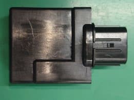
OUCTPMS1R
Jul 02, 2023TPMS ECU
Equipment Class
CYY - Communications Receiver used w/Pt 15 Transmitter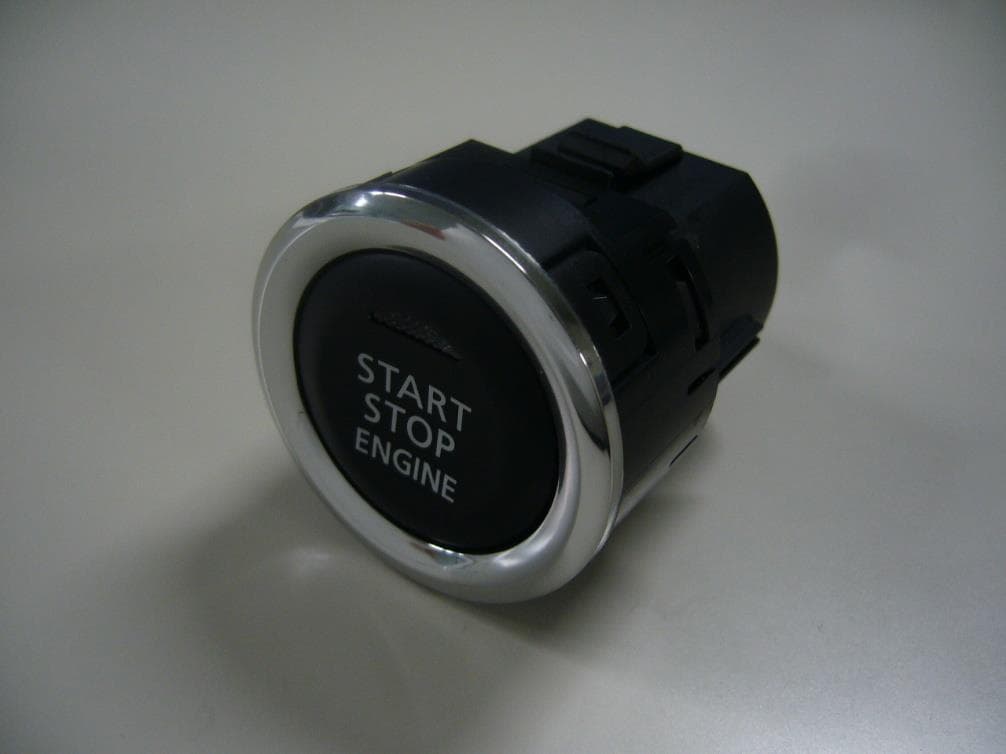
OUCR328E
Nov 29, 2020Transmitter of Keyless Entry System
Equipment Class
DCD - Part 15 Low Power Transmitter Below 1705 kHz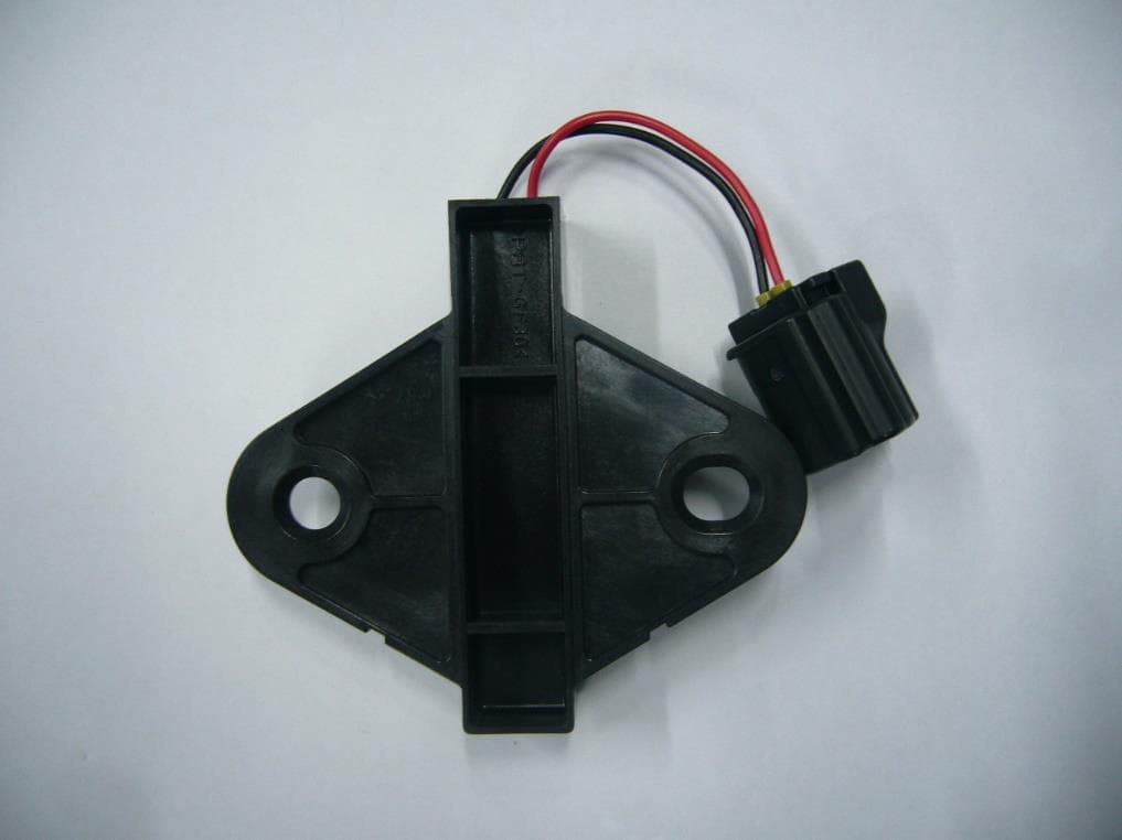
OUCR515E
Nov 29, 2020Transmitter of Keyless Entry System
Equipment Class
DCD - Part 15 Low Power Transmitter Below 1705 kHz
OUC744M-KEY-N
Sep 23, 2020Keyless Operation Key (FOB)
Equipment Class
DSC - Part 15 Security/Remote Control Transmitter
OUCGGM-M018
Aug 04, 2020ETACS
Equipment Class
CYY - Communications Receiver used w/Pt 15 Transmitter