OUCGHW-M002EV Remote Stick
NIDEC MOBILITY CORPORATION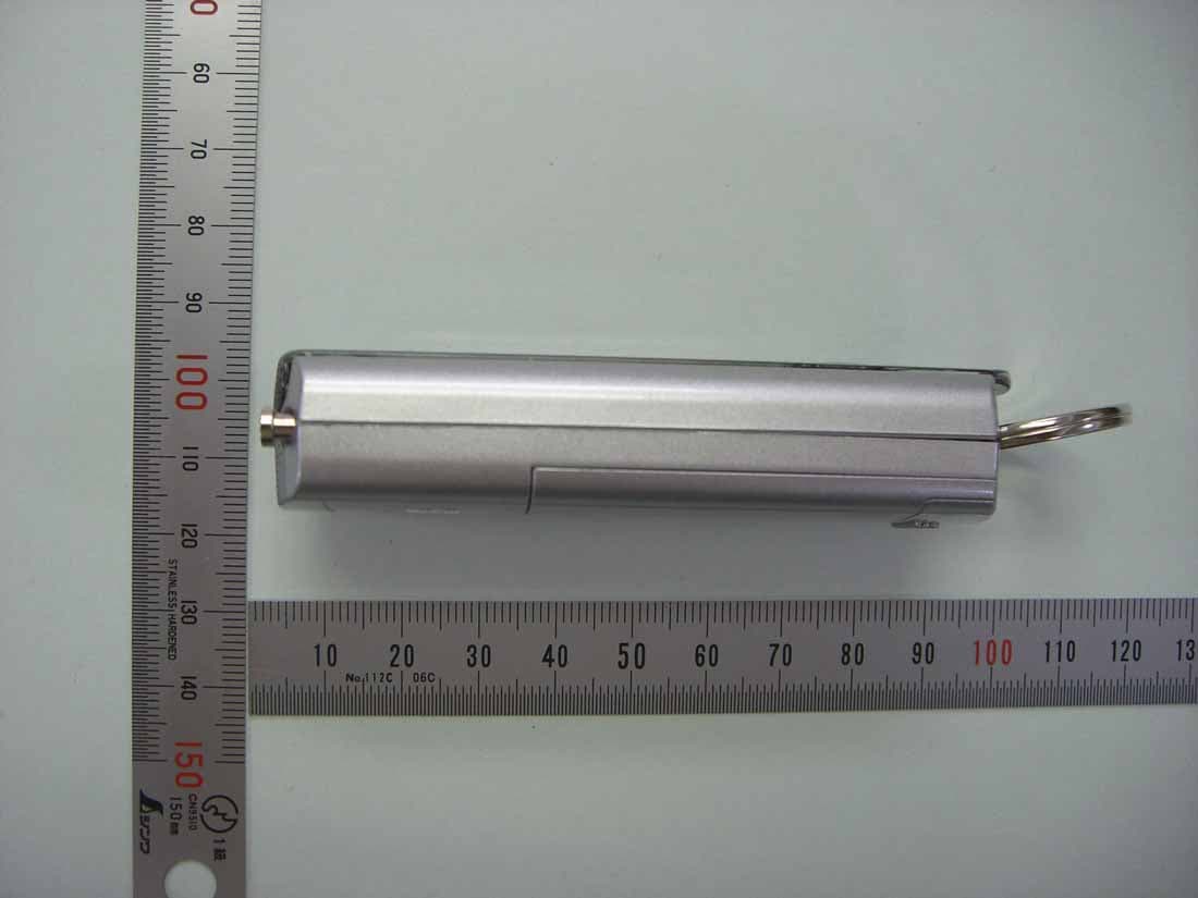
Click to zoom
Application Details
- Equipment Class
- DXT - Part 15 Low Power Transceiver, Rx Verified
- Date of Grant
- Mar 09, 2011
- Application Purpose
- Original Equipment
- Date of Application
- Mar 09, 2011
- Equipment Note
- EV Remote Stick
- Frequency Range
- 926.85000000 - 926.85000000
- Company
- NIDEC MOBILITY CORPORATION
- Country
- Japan
Documents & Files
Document Text
Text extracted from the exhibit documents filed with the FCC. Open a document above to read the original.
Users Manual
EV_REMOTE operation manual Antenna module 3 4 Regulatory compliance Configuration Part names Stick LCD Power / Link button Mode setting button Manual charge button Setting button (UP) Product label Battery cover Product label CN2 connector CN1 connector (antenna connection) Battery replacement Batteries: CR2032 x 2 We recommend that you replace the batteries after one year's use as a guide. How to replace the batteries 1. Remove the battery cover Slide the slide part of the battery cover in the direction of and lift the cover in the direction of to release the hooks of the battery cover ( ). Battery cover Slide part lithium batteries (CR2032) Insert the new batteries (CR2032) with the positive ( + ) side facing up. 2. Replace the batteries 3. Place the battery cover After inserting the hooks of the battery cover ( ), lower the cover into position ( ) and slide the slide part in the direction of . Main specifications After sales service How to use For after sales service, contact : OMRON Automotive Electronics Co. Ltd. 6368 nenjyozaka, okusa Komaki, Aichi 485-0802 JAPAN Tel: +81 568 78 6392 URL: http://www.oae.omron.co.jp Stick Antenna module Transmission frequency 926.85 MHz band (FCC/IC), 869.85 MHz band (EU) Transmission power < 50 mV/m (FCC/IC), < 5mW e.r.p (EU) Antenna 1/4 lambda rod antenna Switches Power on/off, Mode, Charge, Setting Battery Lithium battery (CR2032 x 2) Dimensions 88.4 mm x 32 mm x 18 mm ( not including protrusion) Weight 35 g Link state acknowledgment Buzzer / LCD Transmission frequency 926.85 MHz band (FCC/IC), 869.85 MHz band (EU) Transmission power < 50 mV/m (FCC/IC), < 5mW e.r.p (EU) Power supply 5 V Current consumption 1.5 mA (for receiving) Antenna 1/4 lambda printed antenna Operation temperature range -10 C to +70 C Operation temperature range -30 C to +85 C Dimensions 52 mm x 25 mm x 52 mm Weight 35 g Turning the power of the stick on Setting the charge time Setting the air conditioner Turning the power of the stick off Pressing the Power/Link button for more than 1 second turns the power of the stick on (with a buzzer sound) and the stick starts transmitting a request signal to obtain vehicle information. If a response signal from the vehicle is properly received, the vehicle information will be displayed on the LCD with a buzzer sound. The time till charging is started (charge wait time) and the charging time can be set with the stick. Caution When pulling the antenan out or putting it back, move it straight up/down with holding the top of the antenna. The antenna may be damaged if being pulled with brute force or bended. Pressing the mode setting button once while the vehicle informaiotn is displayed on the LCD enables the charge wait time setting mode. In the charge wait time setting mode, the charge wait time can be set with the setting button. After setting the wait time, the setting information will be sent to the vehicle by pressing the Power/Link button. If a response signal from the vehicle is properly received, the setting information will be displayed on the LCD with a buzzer sound. By pressing the mode setting button once during the charge wait time setting mode, the stick is set to the charge time setting mode. Set the charge time in the same way as done for setting the charge wait time. Pressing the manual charge button resets the timer setting. The car air conditioner can be controlled with the stick prior to getting into a car. Pressing the mode setting button once in the charge time setting mode enables the air conditioner setting mode. Select the temperature you want with the setting button and press the Power/Link button to send the setting information to the vehicle. If a response signal from the vehicle is properly received, the setting information will be displayed on the LCD with a buzzer sound. Pressing the Power/Link button for more than 3 seconds while the power is on turns the power of the stick off. Al so no button operation for more than 30 seconds automatically turn the power off. Setting button (DOWN) FCC/IC WARNING Any changes or modifications not expressly approved by the party responsible for product compliance could void the user's authority to operate the equipment. This device complies with Part 15 of FCC Rules and RSS-Gen of IC Rules. Operation is subject to the following two conditions: (1) this device may not cause interference, and (2) this device must accept any interference, including interference that may cause undesired operation of this device. Declaration of Conformity with Regard to the R&TTE Directive 1999/5/EC The following standards were applied: (R&TTE Directive 1999/5/EEC) EN 60950-1: 2006 + A11:2009 EN 300 220-2 V.2.3.1 EN 301 489-3 V.1.4.1 EN 62311:2008 Hereby, OMRON Automotive Electronics Co. Ltd., declares that Stick / Antenna module are in compliance with the essential requirements and other relevant provisions of Directive 1999/5/EC.
ID Label/Location Info
Label and Label Location FCC ID: OUCGHW-M002 IC: 850G-GHWM002
Test Report
NVLAP Lab code: 100414-0 FCC CFR47 PART 15 SUBPART C INDUSTRY CANADA RSS-210 ISSUE 8 CERTIFICATION TEST REPORT FOR EV REMOTE STICK MODEL NUMBER: GHW-M002 FCC ID: OUCGHW-M002 IC: 850G-GHWM002 REPORT NUMBER: 11J13652-2 ISSUE DATE: MARCH 3, 2011 Prepared for OMRON CORPORATION 6368 NENJOZAKA, OKUSA KOMAKI, AICHI, 485-0802, JAPAN Prepared by COMPLIANCE CERTIFICATION SERVICES 47173 BENICIA STREET FREMONT, CA 94538, U.S.A. TEL: (510) 771-1000 FAX: (510) 661-0888 REPORT NO: 11J13652-2 DATE: MARCH 3, 2011 FCC ID: OUCGHW-M002 IC: 850G-GHWM002 Page 2 of 19 COMPLIANCE CERTIFICATION SERVICES (UL CCS) FORM NO: CCSUP4701C 47173 BENICIA STREET, FREMONT, CA 94538, USA TEL: (510) 771-1000 FAX: (510) 661-0888 This report shall not be reproduced except in full, without the written approval of UL CCS. Revision History Rev. Issue Date Revisions Revised By -- 03/03/11 Initial Issue M. Ferrer REPORT NO: 11J13652-2 DATE: MARCH 3, 2011 FCC ID: OUCGHW-M002 IC: 850G-GHWM002 Page 3 of 19 COMPLIANCE CERTIFICATION SERVICES (UL CCS) FORM NO: CCSUP4701C 47173 BENICIA STREET, FREMONT, CA 94538, USA TEL: (510) 771-1000 FAX: (510) 661-0888 This report shall not be reproduced except in full, without the written approval of UL CCS. TABLE OF CONTENTS 1. ATTESTATION OF TEST RESULTS ..................................................................................... 4 2. TEST METHODOLOGY.......................................................................................................... 5 3. FACILITIES AND ACCREDITATION ..................................................................................... 5 4. CALIBRATION AND UNCERTAINTY.................................................................................... 5 4.1. MEASURING INSTRUMENT CALIBRATION .................................................................. 5 4.2. SAMPLE CALCULATION ................................................................................................. 5 4.3. MEASUREMENT UNCERTAINTY ................................................................................... 5 5. EQUIPMENT UNDER TEST ................................................................................................... 6 5.1. DESCRIPTION OF EUT ................................................................................................... 6 5.2. DESCRIPTION OF AVAILABLE ANTENNAS.................................................................. 6 5.3. SOFTWARE AND FIRMWARE ........................................................................................ 6 5.4. WORST-CASE CONFIGURATION AND MODE ............................................................. 6 5.5. DESCRIPTION OF TEST SETUP.................................................................................... 7 6. TEST AND MEASUREMENT EQUIPMENT .......................................................................... 9 7. ANTENNA PORT TEST RESULTS...................................................................................... 10 7.1.1. 99% BANDWIDTH ................................................................................................... 10 8. RADIATED TEST RESULTS................................................................................................ 11 8.1. LIMITS AND PROCEDURE ........................................................................................... 11 8.2. TRANSMITTER BELOW 1 GHz..................................................................................... 12 8.3. TRANSMITTER ABOVE 1 GHz ..................................................................................... 15 8.4. RECEIVER BELOW 1 GHz ............................................................................................ 16 8.5. RECEIVER ABOVE 1 GHz............................................................................................. 17 9. SETUP PHOTOS .................................................................................................................. 18 REPORT NO: 11J13652-2 DATE: MARCH 3, 2011 FCC ID: OUCGHW-M002 IC: 850G-GHWM002 Page 4 of 19 COMPLIANCE CERTIFICATION SERVICES (UL CCS) FORM NO: CCSUP4701C 47173 BENICIA STREET, FREMONT, CA 94538, USA TEL: (510) 771-1000 FAX: (510) 661-0888 This report shall not be reproduced except in full, without the written approval of UL CCS. 1. ATTESTATION OF TEST RESULTS COMPANY NAME: OMRON CORPORATION 6368 NENJOZAKA, OKUSA KOMAKI, AICHI, 485-0802, JAPAN EUT DESCRIPTION: EV REMOTE STICK MODEL: GHW-M002 SERIAL NUMBER: 11 DATE TESTED: FEBRUARY 25, 2011 – MARCH 2, 2011 APPLICABLE STANDARDS STANDARD TEST RESULTS CFR 47 Part 15 Subpart C Pass INDUSTRY CANADA RSS-210 Issue 8 Annex 2.9 Pass INDUSTRY CANADA RSS-GEN Issue 3 Pass Underwriters Laboratories tested the above equipment in accordance with the requirements set forth in the above standards. All indications of Pass/Fail in this report are opinions expressed by UL based on interpretations and/or observations of test results. Measurement Uncertainties were not taken into account and are published for informational purposes only. The test results show that the equipment tested is capable of demonstrating compliance with the requirements as documented in this report. Note: The results documented in this report apply only to the tested sample, under the conditions and modes of operation as described herein. This document may not be altered or revised in any way unless done so by UL and all revisions are duly noted in the revisions section. Any alteration of this document not carried out by UL will constitute fraud and shall nullify the document. This report must not be used by the client to claim product certification, approval, or endorsement by NVLAP, NIST, any agency of the Federal Government, or any agency of any government. Approved & Released For UL CCS By: Tested By: THU CHAN MICHAEL FERRER ENGINEERING MANAGER SENOIR PROJECT ENGINEER UL CCS UNDERWRITERS LABORATORIES REPORT NO: 11J13652-2 DATE: MARCH 3, 2011 FCC ID: OUCGHW-M002 IC: 850G-GHWM002 Page 5 of 1…
Text truncated - open the document above for the full version.
Test Setup Photos
REPORT NO: 11J13652-2 DATE: MARCH 3, 2011 FCC ID: OUCGHW-M002 IC: 850G-GHWM002 Page 18 of 19 COMPLIANCE CERTIFICATION SERVICES (UL CCS) FORM NO: CCSUP4701C 47173 BENICIA STREET, FREMONT, CA 94538, USA TEL: (510) 771-1000 FAX: (510) 661-0888 This report shall not be reproduced except in full, without the written approval of UL CCS. 9. SETUP PHOTOS Examples shown below REPORT NO: 11J13652-2 DATE: MARCH 3, 2011 FCC ID: OUCGHW-M002 IC: 850G-GHWM002 Page 19 of 19 COMPLIANCE CERTIFICATION SERVICES (UL CCS) FORM NO: CCSUP4701C 47173 BENICIA STREET, FREMONT, CA 94538, USA TEL: (510) 771-1000 FAX: (510) 661-0888 This report shall not be reproduced except in full, without the written approval of UL CCS. X-axis Y-axis Z-axis END OF REPORT
Contact Information
Applicant
Shinya Takenouchi(Manager)
Test Firm
UL LLCRick Titus
Technical Specifications
| # | Rule Parts | Frequency Range | Power Output |
|---|---|---|---|
| 1 | 15C | 926.85 MHz - 926.85 MHz | - |
Other Applications from NIDEC MOBILITY CORPORATION
OUCTPMS1R
Jul 02, 2023TPMS ECU
Equipment Class
CYY - Communications Receiver used w/Pt 15 Transmitter
OUCR328E
Nov 29, 2020Transmitter of Keyless Entry System
Equipment Class
DCD - Part 15 Low Power Transmitter Below 1705 kHz
OUCR515E
Nov 29, 2020Transmitter of Keyless Entry System
Equipment Class
DCD - Part 15 Low Power Transmitter Below 1705 kHz
OUC744M-KEY-N
Sep 23, 2020Keyless Operation Key (FOB)
Equipment Class
DSC - Part 15 Security/Remote Control Transmitter
OUCGGM-M018
Aug 04, 2020ETACS
Equipment Class
CYY - Communications Receiver used w/Pt 15 Transmitter