OUCJ166NTransmitter of Keyless Entry System
NIDEC MOBILITY CORPORATION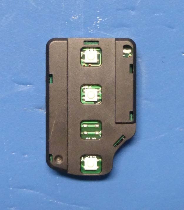
Click to zoom
Application Details
- Equipment Class
- DSC - Part 15 Security/Remote Control Transmitter
- Date of Grant
- Apr 20, 2015
- Application Purpose
- Original Equipment
- Date of Application
- Apr 16, 2015
- Equipment Note
- Transmitter of Keyless Entry System
- Frequency Range
- 315.00000000 - 315.00000000
- Company
- NIDEC MOBILITY CORPORATION
- Country
- Japan
Documents & Files
Document Text
Text extracted from the exhibit documents filed with the FCC. Open a document above to read the original.
Users Manual
WARNING - Changes or modifications not expressly approved by the party responsible for compliance could void the user’s authority to operate the equipment. Your Keyless Operation Key (FOB) operates on a radio frequency subject to Federal Communications Commission (FCC) Rules (For vehicle sold in U.S.A.) and Industry Canada Rules (For vehicles sold in Canada). This device complies with part 15 of FCC Rules and Industry Canada licence-exempt RSS standard(s). Operation is subject to the following two conditions: - This device may not cause harmful interference, and - This device must accept any interference, including interference that may cause undesired operation of this device. Since this device is always used with vehicle, it is not sold to general end users directly. Therefore there is no user manual of this device. The following information must be described on the user manual of the vehicle; AVERTISSEMENT - Tout changement ou toute modification effectués par l’utilisateur et dont la conformité n’est pas expressément approvée par l’organisme responsable de sa conformité peut entraîner l’annulation de droit de cet utilisateur de se servir de l’équipment. Votre clé de fonctionnement sans clé (FOB) fonctionne sur une fréquence radio relevant de la réglementation établie par la Commission fédérale des communications (FCC) (pour les véhicules vendus aux États-Unis) et de la réglementation établie par Industrie Canada (pour les véhicules vendus au Canada). Cet appareil est conforme à la section 15 du Réglement de la FCC et du CNR d'Industrie Canada applicable aux appareils radio exempts de licence. Son fonctionnement est soumis aux deux conditions suivantes : - Ce dispositif ne peut causer d’interférences. - Ce dispositif doit accepter toute interférences, y compris les interférences pouvant provoquer un fonctionnment indésirable de ce dispositif. CONFIDENTIAL 2. User’s manual REMOTE TRANSMITTER (installed inside the grip) You can lock and unlock your vehicle with the remote transmitter. LOCK When you push the LOCK button, all the doors are lock. You cannot lock any of the doors with the module, remote transmitter if any door is open or the key is in the Key cylinder. UNLOCK When you push the UNLOCK button once, only the driver’s door unlocks. The remaining door unlock when you push the button a second time. If you unlock the doors with the remote transmitter, but do not open any of the doors within 30 seconds, the doors are relocked automatically. You cannot unlock any of the doors with the transmitter if the key is in the key cylinder. BOOT RELEASE (Option) When you press the TRUNK button twice, the boots is open. The boot is not open if the key is in the key cylinder. PANIC MODE When you press the PANIC button, the vehicle starts sounding the horn and flashing the headlight intermittently. These functions continue for 180 seconds unless any of the buttons on the transmitter are pressed. TRUNK LOCK UNLOCK PANIC - 2 - Copyright 2015 OMRON Automotive Electronics Co. Ltd. All right reserved. This document and its contents may be used for our application only. FCC ID, IC Number and Model Number of this transmitter are indicated on the transmitter, but the transmitter is covered with the keyless entry case under normal conditions. As this is the transmitter for keyless entry system used in the vehicle, operation instructions for the transmitter and procedures to open the transmitter’s case are explained in the “procedure for replacing the key battery” section of the user’s manual for the vehicle. Consequently, the following note and illustration are shown in the “procedure for replacing the key battery” section of the user’s manual for the vehicle. ●The Federal Communications Commission (FCC) ID number, the Industry Canada (IC) number and the model number (radio certification) are indicated in the illustrated position.
External Photos
CONFIDENTIAL 7. Photographs Figure 7.1 appearance (front view) Figure 7.2 appearance (back view) - 10 - Copyright 2015 OMRON Automotive Electronics Co. Ltd. All right reserved. This document and its contents may be used for our application only. CONFIDENTIAL Figure 7.3 appearance (top view) Figure 7.4 appearance (back view) Figure 7.5 appearance (right side view) Figure 7.6 appearance (left side view) - 11 - Copyright 2015 OMRON Automotive Electronics Co. Ltd. All right reserved. This document and its contents may be used for our application only.
Internal Photos
CONFIDENTIAL Figure 7.7 PCB (front view) Figure 7.8 PCB(back view) - 12 - Copyright 2015 OMRON Automotive Electronics Co. Ltd. All right reserved. This document and its contents may be used for our application only. J166N Antenna [basic model] ■The antenna is formed as a part of pattern* on the PWB. ( * highligted by red lines on photos) Pattern of side A and side B are connected by via-hole. CONFIDENTIAL Copyright 2015 OMRON Automotive Electronics Co. Ltd. All right reserved. This document and its contents may be used for our application only. side A side B
Test Report
Test report No. : 10605030H-A-R1 Page : 2 of 17 Issued date : April 7, 2015 Revised date : April 16, 2015 FCC ID : OUCJ166N UL Japan, Inc. Ise EMC Lab. 4383-326 Asama-cho, Ise-shi, Mie-ken 516-0021 JAPAN Telephone : +81 596 24 8999 Facsimile : +81 596 24 8124 REVISION HISTORY Original Test Report No.: 10605030H-A Revision Test report No. Date Page revised Contents - (Original) 10605030H-A April 7, 2015 - - 1 10605030H-A-R1 April 16, 2015 P. 5 Correction of FCC Part 15.31 (e) statement Test report No. : 10605030H-A-R1 Page : 3 of 17 Issued date : April 7, 2015 Revised date : April 16, 2015 FCC ID : OUCJ166N UL Japan, Inc. Ise EMC Lab. 4383-326 Asama-cho, Ise-shi, Mie-ken 516-0021 JAPAN Telephone : +81 596 24 8999 Facsimile : +81 596 24 8124 CONTENTS PAGE SECTION 1: Customer information ·············································································· 4 SECTION 2: Equipment under test (E.U.T.) ···································································· 4 SECTION 3: Test specification, procedures & results························································· 5 SECTION 4: Operation of E.U.T. during testing ······························································· 8 SECTION 5: Radiated emission (Electric Field Strength of Fundamental and Spurious Emission) 9 SECTION 6: Automatically deactivate ········································································· 10 SECTION 7: -20dB and 99% Occupied Bandwidth ························································· 10 APPENDIX 1: Data of EMI test ·················································································· 11 Automatically deactivate................................................................................................................... 11 Radiated Emission (Electric Field Strength of Fundamental and Spurious Emission) ..................... 12 -20dB and 99% Occupied Bandwidth ............................................................................................... 13 Duty Cycle ........................................................................................................................................ 14 APPENDIX 2: Test Instruments ·················································································· 15 APPENDIX 3: Photographs of test setup ······································································· 16 Radiated emission ............................................................................................................................. 16 Worst case position ........................................................................................................................... 17 Test report No. : 10605030H-A-R1 Page : 4 of 17 Issued date : April 7, 2015 Revised date : April 16, 2015 FCC ID : OUCJ166N UL Japan, Inc. Ise EMC Lab. 4383-326 Asama-cho, Ise-shi, Mie-ken 516-0021 JAPAN Telephone : +81 596 24 8999 Facsimile : +81 596 24 8124 SECTION 1: Customer information Company Name : OMRON Automotive Electronics Co. Ltd. Address : 6368 NENJOZAKA OKUSA KOMAKI AICHI, 485-0802 JAPAN Telephone Number : +81-568-78-6159 Facsimile Number : +81-568-78-7659 Contact Person : Masashi Matsuda SECTION 2: Equipment under test (E.U.T.) 2.1 Identification of E.U.T. Type of Equipment : Transmitter of Keyless Entry System Model No. : J166N Serial No. : Refer to Section 4, Clause 4.2 Rating : DC 3.0V Receipt Date of Sample : December 13, 2014 Country of Mass-production : Japan and Thailand Condition of EUT : Production prototype (Not for Sale: This sample is equivalent to mass-produced items.) Modification of EUT : No Modification by the test lab 2.2 Product Description Model No: J166N (referred to as the EUT in this report) is the Transmitter of Keyless Entry System. General Specification Clock frequencies in the system : 2MHz, 9.844MHz Radio Specification Radio Type : Transmitter Frequency of Operation : 315MHz Modulation : FSK Power Supply (radio part input) : DC 3.0V Antenna type : Integral (Pattern Antena) * The original model No.: J166N has variant models. The differences of original model and variant models are only the number of switches and protocol. Therefore, the test was performed with the representative original model which was the worst one. Test report No. : 10605030H-A-R1 Page : 5 of 17 Issued date : April 7, 2015 Revised date : April 16, 2015 FCC ID : OUCJ166N UL Japan, Inc. Ise EMC Lab. 4383-326 Asama-cho, Ise-shi, Mie-ken 516-0021 JAPAN Telephone : +81 596 24 8999 Facsimile : +81 596 24 8124 SECTION 3: Test specification, procedures & results 3.1 Test Specification Test Specification : FCC Part 15 Subpart C: 2015, final revised on January 21, 2015 Title : FCC 47CFR Part15 Radio Frequency Device Subpart C Intentional Radiators Section 15.231 Periodic operation in the band 40.66 - 40.70MHz and above 70MHz * The revision on January 21, 2015 does not affect the test specification applied to the EUT. 3.2 Procedures and results Item Test Procedure Specification Worst margin Results Remarks Conducted emission FCC: ANSI C63.4:2009 7. AC powerline conducted emission measurements FCC: Section 15.207 N/A N/A*1) - IC: RSS-Gen 8.8 IC: RSS-Gen 8.8 Automatically Deactivate FCC: ANSI C63.4:2009 13. Measurement of intentional radiators FCC: Section 15.231(a)(1) N/A Complied Radiated IC: - IC: RSS-210 A1.1.1 Electric Field Strength of Fundamental Emission FCC: ANSI C63.4:2009 13. Measurement of intentional radiators FCC: Section 15.231(b) 0.2dB 315.000MHz Horizontal PK with Duty factor Complied Radiated IC: RSS-Gen 6.12 IC: RSS-210 A1.1.2 Electric Field Strength of Spurious Emission FCC: ANSI C63.4:2009 13. Measurement of intentional radiators FCC: Section 15.205 Section 15.209 Section 15.231(b) 0.9dB 2520.000MHz Horizontal PK with Duty factor Complied Radiated IC: RSS-Gen 6.13 IC: RSS-210 A1.1.2, 2.5.1 RSS-Gen 8.9 -20dB Bandwidth FCC: ANSI C63.4:2009 13. Measurement of intentional radiators FCC: Section 15.231(c) N/A Complied Radiated IC: - I…
Text truncated - open the document above for the full version.
Test Setup Photos
Test report No. : 10605030H-A-R1 Page : 16 of 17 Issued date : April 7, 2015 Revised date : April 16, 2015 FCC ID : OUCJ166N UL Japan, Inc. Ise EMC Lab. 4383-326 Asama-cho, Ise-shi, Mie-ken 516-0021 JAPAN Telephone : +81 596 24 8999 Facsimile : +81 596 24 8124 APPENDIX 3: Photographs of test setup Radiated emission Photo 1 Photo 2 Test report No. : 10605030H-A-R1 Page : 17 of 17 Issued date : April 7, 2015 Revised date : April 16, 2015 FCC ID : OUCJ166N UL Japan, Inc. Ise EMC Lab. 4383-326 Asama-cho, Ise-shi, Mie-ken 516-0021 JAPAN Telephone : +81 596 24 8999 Facsimile : +81 596 24 8124 Worst case position (Horizontal: X-axis/Vertical : Y-axis) X-axis Y-axis Z-axis End of Report
Contact Information
Applicant
Shinya Takenouchi(Manager)
Technical Contact
UL Japan, Inc.Motoya Imura
[email protected]81-596-24-8999
4383-326 Asama-cho, Ise-shi · Mie-ken · Japan
Test Firm
UL Japan, Inc. Head office EMC Lab.Tetsuya Hashimoto
Technical Specifications
| # | Rule Parts | Frequency Range | Power Output |
|---|---|---|---|
| 1 | 15.231 | 315 MHz - 315 MHz | - |
Other Applications from NIDEC MOBILITY CORPORATION
OUCTPMS1R
Jul 02, 2023TPMS ECU
Equipment Class
CYY - Communications Receiver used w/Pt 15 Transmitter
OUCR328E
Nov 29, 2020Transmitter of Keyless Entry System
Equipment Class
DCD - Part 15 Low Power Transmitter Below 1705 kHz
OUCR515E
Nov 29, 2020Transmitter of Keyless Entry System
Equipment Class
DCD - Part 15 Low Power Transmitter Below 1705 kHz
OUC744M-KEY-N
Sep 23, 2020Keyless Operation Key (FOB)
Equipment Class
DSC - Part 15 Security/Remote Control Transmitter
OUCGGM-M018
Aug 04, 2020ETACS
Equipment Class
CYY - Communications Receiver used w/Pt 15 Transmitter