OUCRJ333N-ARemote engine starter (Antenna-M function)
NIDEC MOBILITY CORPORATION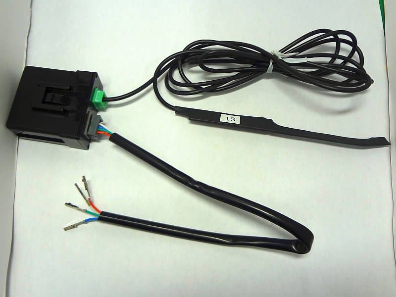
Click to zoom
Application Details
- Equipment Class
- DSS - Part 15 Spread Spectrum Transmitter
- Date of Grant
- Jun 10, 2015
- Application Purpose
- Original Equipment
- Date of Application
- Jun 10, 2015
- Equipment Note
- Remote engine starter (Antenna-M function)
- Frequency Range
- 915.40000000 - 925.00000000
- Company
- NIDEC MOBILITY CORPORATION
- Country
- Japan
Documents & Files
Document Text
Text extracted from the exhibit documents filed with the FCC. Open a document above to read the original.
Users Manual
We recommend that you replace the batteries after one year's use as a guide. Batteries: CR2032 x 2 1. Pressing the Engine control button for more than 1 second. 2. Release the Engine control button, and then press the Unlock/Start button. (The vehicle engine will start.) 3. If a response signal from the vehicle is properly received, the LED indicators will be blinked. 1. Pressing the Engine control button for more than 1 second. 2. Release the Engine control button, and then press the Lock/Stop button. (The vehicle engine will stop.) 3. If a response signal from the vehicle is properly received, the LED indicators will be blinked. ・Pressing the Lock/Stop button, the vehicle door will be locked. ・Pressing the Unlock/Start button, the vehicle door will be unlocked. Remocon Engine Starter operation manual FCC / IC CAUTION Changes or modifications not expressly approved by the party responsible for compliance could void the user’s authority to operate the equipment. Tout changement ou toute modification effectués par l’utilisateur et dont la conformité n’est pas expressément approvée par l’organisme responsable de sa conformité peut entraîner l’annulation de droit de cet utilisateur de se servir de l’équipment. This transmitter must not be co-located or operated in conjunction with any other antenna or transmitter. This device complies with part 15 of FCC Rules and Industry Canada’s licence-exempt RSSs. Operation is subject to the following two conditions: (1) this device may not cause harmful interference, and (2) this device must accept any interference received, including in terference that may cause undesired operation. Le présent appareil est conforme à la partie 15 des règles de la FCC et aux normes des CNR d'Industrie Canada applicables aux appareils radio exempts de licence. L'exploitation est autorisée aux deux conditions suivantes : (1)l'appareil ne doit pas produire de brouillage, et (2)l'appareil doit accepter tout brouillage subi, même si le brouillage est susceptible d'en compromettre le fonctionnement. After sales service 4 Transmission frequency 902 MHz~928MHz band Transmission power < 20mW Antenna chip antenna Switches Lock/Stop, Unlock/Start, Engine control Link state acknowledgment LED indicators Battery Lithium battery (CR2032 x 2) Operation temperature range -20 °C to +60 °C (-4°F to 140°F) Dimensions 81.5 mm x 30 mm x 13 mm ( not including protrusion) Weight 37 g Antenna module Transmission frequency 902 MHz~928MHz band Transmission power < 20mW Power supply 4.2 V Current consumption 3 mA (for receiving) Antenna 1/4 lambda printed antenna Operation temperature range -30 °C to +85 °C (-22°F to 185°F) Dimensions 52 mm x 25 mm x 52 mm Weight 35 g Main specification 3 Door lock / unlock Remote engine stop Remote engine start How to use 2 1. Remove the battery cover Battery cover Remove the screw and the battery cover. Lithium batteries (CR2032 x 2) Screw 2. Take out the old batteries Insert the flathead screw driver which put cloth and take out the old batteries. 3. Replace the new batteries Insert the new batteries (CR2032) with the positive ( + ) side facing up. 4. Place the battery cover Place the battery cover and fasten the screw. How to replace the batteries Battery replacement Key fob LED indicators Lock/Stop button Unlock/Start button Engine control button Ring Battery cover Product label Parts names Configuration 1 For after sales service, contact : OMRON Automotive Electronics Co. Ltd. 6368 nenjyozaka, okusa Komaki, Aichi 485-0802 JAPAN URL: http://www.oae.omron.co.jp Regulatory compliance Key fob Regulatory compliance This equipment complies with FCC/IC radiation exposure limits set forth for an uncontrolled environment and meets the FCC radio frequency (RF) Exposure Guidelines and RSS-102 of the IC radio frequency (RF) Exposure rules. This equipment has very low levels of RF energy that are deemed to comply without testing of specific absorption rate (SAR). Cet équipement est conforme aux limites d’exposition aux rayonnements énoncées pour un environnement non contrôlé et respecte les règles les radioélectriques (RF) de la FCC lignes directrices d'exposition et d’exposition aux fréquences radioélectriques (RF) CNR-102 de l’IC. Cet équipement émet une énergie RF très faible qui est considérée conforme sans évaluation du débit d’absorption spécifique (DAS). [Key fob] This equipment complies with FCC/IC radiation exposure limits set forth for an uncontrolled environment and meets the FCC radio frequency (RF) Exposure Guidelines and RSS-102 of the IC radio frequency (RF) Exposure rules. This equipment has very low levels of RF energy that it deemed to comply without maximum permissive exposure evaluation (MPE). Cet équipement est conforme aux limites d’exposition aux rayonnements énoncées pour un environnement non contrôlé et respecte les règles les radioélectriques (RF) de la FCC lignes directrices d'exposition et d’exposition aux fréquences radioélectriques (RF) CNR-102 de l’IC. Cet équipement émet une énergie RF très faible qui est considérée conforme sans évaluation de l’exposition maximale autorisée (MPE). [Antenna module]
External Photos
External Photo OMRON Automotive Electronics. Ltd. Remote engine starter [Model: RJ333N-A] External Photo Top External Photo Bottom External Photo OMRON Automotive Electronics. Ltd. Remote engine starter [Model: RJ333N-A] External Photo Front External Photo Left External Photo OMRON Automotive Electronics. Ltd. Remote engine starter [Model: RJ333N-A] External Photo with antenna
ID Label/Location Info
●The Federal Communications Commission (FCC) ID number, the Industry Canada (IC) number and the model number (radio certification) are indicated in the illustrated position. This printed label is affixed to the surface of the case. MODEL: RJ333N-A FCC ID : OUCRJ333N-A IC : 850G-RJ333NA Omron S/No.FB******
Internal Photos
Internal Photo OMRON Automotive Electronics. Ltd. Remote engine starter [Model: RJ333N-A] Internal Photo Side A Internal Photo Side B
RF Exposure Info
UL Japan, Inc. Ise EMC Lab 4383-326 Asama-cho, Ise-shi, Mie 516-0021 Japan T:: +81.596.24.8999 / F:: +81.596.24.8124 / W:: ul.com/jp June 10, 2015 UL Japan, Inc. 4383-326 Asama-cho, Ise-shi, Mie 516-0021 Japan FCC ID: OUCRJ333N-A To whom it may concern, We, UL Japan, Inc, hereby declare that Remote engine starter (Antenna-M function), model: RJ333N- A (FCC ID: OUCRJ333N-A) of OMRON Automotive Electronics Co. Ltd. is exempt from RF exposure SAR evaluation as its output power meets the exclusion limits stated in KDB 447498D01(v05r02). KDB 447498D01(v05r02) has the following exclusion for portable devices: The 1g and 10g SAR test exclusion thresholds for 100 MHz to 6 GHz at test separation distances ≤ 50 mm are determined by: [(max. power of channel, including tune-up tolerance, mW)/(min. test separation distance, mm)] ·[√f(GHz)] ≤ 3.0 for 1-g SAR and ≤ 7.5 for 10-g extremity SAR, where •f(GHz) is the RF channel transmit frequency in GHz •Power and distance are rounded to the nearest mW and mm before calculation •The result is rounded to one decimal place for comparison The test exclusions are applicable only when the minimum test separation distance is ≤ 50 mm and for transmission frequencies between 100 MHz and 6 GHz. When the minimum test separation distance is < 5 mm, a distance of 5 mm is applied to determine SAR test exclusion. This device has f = 0.925 GHz and distance = 5 mm (minimum separation distance: 5mm was used in the calculation) and the maximum average output power was 8 mW So for this device: 8 mW[maximum average output power]/5 mm[minimum separation distance]*√0.925 = 1.5 *This is less than 3.0, so no SAR is required. Even taking into account the tolerance, this device can be satisfied with the limits. Thank you for your attention to this matter. Motoya Imura Engineer of Ise EMC Lab. Consumer Technology Division UL Japan, Inc.
Test Setup Photos
Test report No. : 10749723H-C-R1 Page : 31 of 32 Issued date : May 15, 2015 Revised data : June 10, 2015 FCC ID : OUCRJ333N-A UL Japan, Inc. Ise EMC Lab. 4383-326 Asama-cho, Ise-shi, Mie-ken 516-0021 JAPAN Telephone : +81 596 24 8999 Facsimile : +81 596 24 8124 APPENDIX 3: Photographs of test setup Radiated Spurious Emission Photo 1 Photo 2 Test report No. : 10749723H-C-R1 Page : 32 of 32 Issued date : May 15, 2015 Revised data : June 10, 2015 FCC ID : OUCRJ333N-A UL Japan, Inc. Ise EMC Lab. 4383-326 Asama-cho, Ise-shi, Mie-ken 516-0021 JAPAN Telephone : +81 596 24 8999 Facsimile : +81 596 24 8124 Worst Case Position Below 1GHz Antenna :Horizontal: X-axis / Vertical: Y-axis Above 1GHz Antenna :Horizontal: X-axis / Vertical: X-axis) Below 1GHz ANT-M :Horizontal: X-axis / Vertical: X-axis) Above 1GHz ANT-M :Horizontal: X-axis / Vertical:X-axis) Antenna ANT-M X-axis X-axis Y-axis Y-axis Z-axis Z-axis End of Report
Contact Information
Applicant
Shinya Takenouchi(Manager)
Technical Contact
UL Japan, Inc.Motoya Imura
[email protected]81-596-24-8999
4383-326 Asama-cho, Ise-shi · Mie-ken · Japan
Test Firm
UL Japan, Inc. Head office EMC Lab.Tetsuya Hashimoto
Technical Specifications
| # | Rule Parts | Frequency Range | Power Output |
|---|---|---|---|
| 1 | 15C | 915.4 MHz - 925 MHz | 8.30 mW |
Other Applications from NIDEC MOBILITY CORPORATION
OUCTPMS1R
Jul 02, 2023TPMS ECU
Equipment Class
CYY - Communications Receiver used w/Pt 15 Transmitter
OUCR328E
Nov 29, 2020Transmitter of Keyless Entry System
Equipment Class
DCD - Part 15 Low Power Transmitter Below 1705 kHz
OUCR515E
Nov 29, 2020Transmitter of Keyless Entry System
Equipment Class
DCD - Part 15 Low Power Transmitter Below 1705 kHz
OUC744M-KEY-N
Sep 23, 2020Keyless Operation Key (FOB)
Equipment Class
DSC - Part 15 Security/Remote Control Transmitter
OUCGGM-M018
Aug 04, 2020ETACS
Equipment Class
CYY - Communications Receiver used w/Pt 15 Transmitter