OUELINK800LINK800WS
Paul C. Buff, Inc.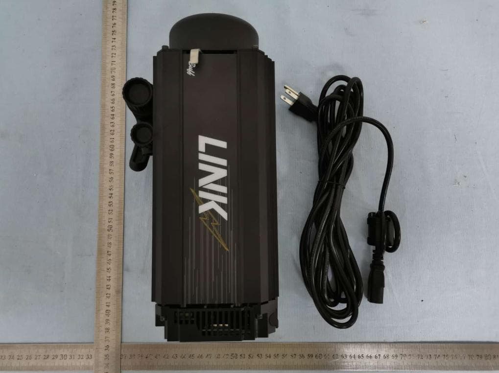
Click to zoom
Application Details
- Equipment Class
- DXX - Part 15 Low Power Communication Device Transmitter
- Date of Grant
- Nov 22, 2020
- Application Purpose
- Original Equipment
- Date of Application
- Nov 22, 2020
- Equipment Note
- LINK800WS
- Frequency Range
- 2427.00000000 - 2457.00000000
- Company
- Paul C. Buff, Inc.
- Country
- United States
Documents & Files
Document Text
Text extracted from the exhibit documents filed with the FCC. Open a document above to read the original.
Users Manual
PRODUCT MANUAL v. 1/2020 WHAT’S INCLUDED: (1) LINK Flash Unit (1) AC Power Cord (1) Gel Diffusion Dome (1) 14mm Flash Tube (1) Shipping Cover ADDITIONAL ITEMS AVAILABLE: LINK Battery | LINK Battery Charger | HUB Remote | Color Gel Diffusion Domes Paul C. Buff Flash Units are designed for professional photography use. As with all electronic equipment, users must observe all warnings and safety precautions. Carefully read all operating instructions and safety instructions before use. WARNING! HIGH VOLTAGE! Flash units contain internal components that can store dangerously high voltages, even when the units are unplugged. Batteries should not be exposed to excessive heat (i.e. direct sunlight, open flame, etc.) GENERAL PRECAUTIONS Do not operate a flash unit on or around flammable materials. Keep the unit away from fire, flames, and heated surfaces. Do not insert any foreign objects into any ventilation holes. Do not carry or store a flash unit together with necklaces, hair pins, nails, paper clips, or any other small metal objects. Do not cover the unit during operation. Air circulation must be permitted. Do not obstruct ventilation holes by covering the unit while in use or by operating from inside a carrying bag. Do not operate or store a flash unit in or around water. High voltage equipment can cause electric shock when operated in or near water. Your flash unit should only be used in dry, moderate conditions where the equipment is protected from rain, dirt, sand and dust. Do not use ungrounded power cords, power outlets or power strips. Paul C. Buff, Inc. Flash Units may only be connected to 3-wire grounded AC outlets to avoid shock hazard. Do not connect the unit to an ungrounded outlet or to a two-wire extension cord or adapter that eliminates the ground prong. Do not use any cords that have been damaged. Paul C. Buff, Inc. flash units contain no user-serviceable parts. Never open, disassemble, or attempt to repair any components. Only qualified technicians should service the system as incorrect disassembly can create an electric shock hazard. Fingers and other foreign objects must never be inserted or dropped inside any of the vents. If the unit has been dropped or damaged, discontinue use and contact customer service. Do not attempt to make any changes or modifications as any modifications made, outside of those performed or approved by Paul C. Buff, Inc., may present hazardous conditions and void the warranty. The only user-replaceable components are the flashtube, cover, and stand mount. NOTE - RADIO FREQUENCY ENERGY The LINK 800WS Flash Unit features a built-in CyberSync transceiver. This unit makes use of the radio spectrum and emits radio frequency energy. Interference can be a factor, as the frequency used is shared with other users and electronics. Please adhere to local regulations when using this device. 3 GENERAL SAFETY INFORMATIONTABLE of CONTENTS GETTING STARTED 4 STAND MOUNT 4 PLACING ON A LIGHT STAND 4 SHIPPING COVER 4 ATTACHING MODIFIERS 5 POWERING YOUR UNIT 5 BACK PANEL DISPLAY 6 POWERING THE UNIT ON/OFF 6 DEFAULT SETTINGS 6 NAVIGATING THE BACK PANEL 7 FLASH MODES 7 MODEL MODES 7 MODELING LIGHT FOR VIDEO USE 8 SYNC MODES 8 FREQUENCY / CHANNEL 8 RECYCLE / READY INDICATOR 8 BATTERY INDICATOR 8 LINK BATTERY 9 CHARGING THE BATTERY 9 HUB REMOTE 10 ATTACHING THE HUB TO YOUR CAMERA 10 POWERING THE HUB ON / OFF 10 REAR DISPLAY 10 BLUETOOTH 10 SETTING THE FREQUENCY 11 SENDING A TEST FIRE 11 TTL MODE 11 HSS MODE 11 CHANGING THE DISPLAY BRIGHTNESS 11 CHARGING THE HUB 11 GENERAL INFORMATION 12 FAQ’S 13 WARRANTY INFORMATION 14 2 paulcbuff.com | [email protected] | 1.800.443.5542 GETTING STARTED The unit arrives with the stand mount tucked under the unit. To release, open the locking handle by pulling out and loosening the large knob by turning counter-clockwise. The stand mount will then move freely. Place the open collar at the base of the stand mount over the stud mount on your light stand. Tighten the small knob, by turning clockwise, to secure. Tighten the large knob, by turning clockwise, while holding the locking handle with your flash unit at your desired angle. Once satisfied with its placement, push the locking handle in towards the stud mount to secure.To readjust the tilt, simply pull the handle outwards from the stand mount, reposition your flash unit, and then push the locking handle in towards the stud mount to secure the placement. Make sure that the unit is secure prior to releasing. STAND MOUNT The stand mount is made of aluminum and features a locking handle, and two knobs. The smaller knob is what attaches the stand mount to the stud of your light stand. The larger knob connects directly to the locking handle and allows you to control and secure the tilt position of the flash unit. SMALL KNOB LARGE KNOB LOCKING HANDLE The shipping cover is made of aluminum and provides protection to the flash tube when transporting or storing your flash unit. You MUST remove the shipping cover prior to turning on the flash unit. REMOVE THE SHIPPING COVER To remove the shipping cover, slide either of the quick-release levers to retract the four faceplate fingers holding the cover. QUICK-RELEASE LEVER SHIPPING COVER QUICK-RELEASE LEVER and HOLDING FINGERS The LINK faceplate utilizes a Balcar mount that has four holding fingers, controlled by the quick-release levers. These holding fingers expand and retract to hold various reflectors as well as speedrings for softbox attachment. The LINK is compatible with all Paul C. Buff, Inc. modifiers. UMBRELLA CHANNEL Located above the faceplate, the umbrella channel is outfitted with internal tension clips to hold an umbrella or PLM in place without any slipping or drooping. The umbrella channel can fit up to a 9mm rod. MAGNETIC ATTACHMENT New to the Paul C. Buff, Inc. line of flash units is a magnetic attachment connection for diffusion (included with the unit), creative color, and color correcting silicone domes (both sold separately). …
Text truncated - open the document above for the full version.
External Photos
FCC ID: OUELINK800 External photo FCC ID: OUELINK800 FCC ID: OUELINK800
ID Label/Location Info
FCC ID: OUELINK800 Label & Label Location
Internal Photos
FCC ID: OUELINK800 Internal photo FCC ID: OUELINK800 FCC ID: OUELINK800 FCC ID: OUELINK800 FCC ID: OUELINK800 RF Antenna RF Chip FCC ID: OUELINK800
Operational Description
Paul C. Buff, Inc. Declaration concerning Antenna Specification It is hereby declared that the product Model No.: LINK800WS FCC ID: OUELINK800 fulfills the requirement in FCC test relating to the antenna type. The device specified above confirms to the FCC recommendations for PCB antenna type(s) described below: Model No. of antenna: ANT1 Type of antenna: PCB antenna Gain of the antenna: -1 dBi Frequency range: 2427-2457MHz The mounting of the antenna is fixed to the radio module and no other antenna should be used. Company name: Paul C. Buff, Inc. Address: 2725 Bransford Ave City: Nashville TN ZIP / Postal code: 37204 Country: United States Place: Brian Lennon Date: 2020-11-20 Signature:
RF Exposure Info
Dongguan Nore Testing Center Co., Ltd. Report No.: NTC2004096FV00-1 FCC ID: OUELINK800 RF EXPOSURE EVALUATION EUT Specification EUT LINK800WS Frequency band (Operating) WLAN: 2.412GHz ~ 2.462GHz WLAN: 5.18GHz ~ 5.32GHz / 5.50GHz ~ 5.70GHz WLAN: 5.745GHz ~ 5825GHz Others(SRD: 2.427GHz ~ 2.457GHz) Device category Portable (<20cm separation) Mobile (>20cm separation) Others ___ Antenna diversity Single antenna Multiple antennas Tx diversity Rx diversity Tx/Rx diversity Max. output power 73.29 dBuV/m (0.006mW) Antenna gain -1 dBi Evaluation applied MPE Evaluation SAR Evaluation Limits for Maximum Permissible Exposure (MPE) Frequency Range(MHz) Electric Field Strength(V/m) Magnetic Field Strength(A/m) Power Density(mW/cm 2 ) 300-1500 -- -- F/1500 1500-100000 -- -- 1 Dongguan Nore Testing Center Co., Ltd. Report No.: NTC2004096FV00-1 FCC ID: OUELINK800 Friis transmission formula: Pd=(Pout*G)\(4*pi*R 2 ) Where Pd= Power density in mW/cm 2 Pout=output power to antenna in Mw G= gain of antenna in linear scale Pi=3.1416 R= distance between observation point and center of the radiator in cm Pd the limit of MPE, 1mW/cm2. If we know the maximum gain of the antenna and total power input to the antenna, through the calculation, we will know the distance where the MPE limit is reached. Measurement Result EIRP=E-104.8+20logD=70.88-104.8+20log3= -24.38dBm Channel Gain Channel Frequency (MHz) Max Output power (dBm) Tolerance Max Tune-UP power (mW) Power density at 20cm (mW/ cm 2 ) Power density Limits (mW/cm 2 ) 2.4GHz Low -1 2427 -24.38 ± 0.5 0.004 0.000001 1 Middle -1 2441 -21.97 ± 0.5 0.007 0.000001 1 High -1 2457 -22.17 ± 0.5 0.007 0.000001 1
Test Report
Dongguan Nore Testing Center Co., Ltd. Report No.: NTC2004096FV00 FCC ID: OUELINK800 Page 2 of 27 Table of Contents 1. GENERAL INFORMATION ................................................................................................ 4 1.1 PRODUCT DESCRIPTION FOR EQUIPMENT UNDER TEST ................................................................. 4 1.2 RELATED SUBMITTAL(S) / GRANT (S) ............................................................................................ 6 1.3 TEST METHODOLOGY .................................................................................................................. 6 1.4 EQUIPMENT MODIFICATIONS ........................................................................................................ 6 1.5 SUPPORT DEVICE ....................................................................................................................... 6 1.6 TEST FACILITY AND LOCATION ..................................................................................................... 7 1.7 SUMMARY OF TEST RESULTS ....................................................................................................... 8 2. SYSTEM TEST CONFIGURATION .................................................................................... 9 2.1 EUT CONFIGURATION ................................................................................................................. 9 2.2 DESCRIPTION OF TEST MODES ..................................................................................................... 9 2.3 EUT EXERCISE ........................................................................................................................... 9 3. CONDUCTED EMISSIONS TEST .................................................................................... 10 3.1 TEST SET-UP (BLOCK DIAGRAM OF CONFIGURATION) ................................................................ 10 3.2 TEST CONDITION ....................................................................................................................... 10 3.3 MEASUREMENT RESULTS .......................................................................................................... 10 4. RADIATED EMISSION TEST ........................................................................................... 13 4.1 TEST SET-UP (BLOCK DIAGRAM OF CONFIGURATION) ................................................................ 13 4.2 MEASUREMENT PROCEDURE ..................................................................................................... 14 4.3 LIMIT ........................................................................................................................................ 15 4.4 MEASUREMENT RESULTS ................................................................................................. 16 5. 20DB BANDWIDTH .......................................................................................................... 20 5.1 MEASUREMENT PROCEDURE ..................................................................................................... 20 5.2 TEST SET-UP (BLOCK DIAGRAM OF CONFIGURATION) ................................................................ 20 5.3 MEASUREMENT RESULTS .......................................................................................................... 20 6. BAND EDGE .................................................................................................................... 23 6.1 MEASUREMENT PROCEDURE ..................................................................................................... 23 6.2 LIMIT ........................................................................................................................................ 23 6.3 MEASUREMENT RESULTS .......................................................................................................... 23 7. ANTENNA REQUIREMENT ............................................................................................. 26 7.1 MEASUREMENT PROCEDURE ..................................................................................................... 26 7.2 MEASUREMENT RESULTS .......................................................................................................... 26 8. TEST EQUIPMENT LIST .................................................................................................. 27 Dongguan Nore Testing Center Co., Ltd. Report No.: NTC2004096FV00 FCC ID: OUELINK800 Page 3 of 27 Revision History of This Test Report Report Number Description Issued Date NTC2004096FV00 Initial Issue 2020-11-20 Dongguan Nore Testing Center Co., Ltd. Report No.: NTC2004096FV00 FCC ID: OUELINK800 Page 4 of 27 1. GENERAL INFORMATION 1.1 Product Description for Equipment under Test Product Name : LINK800WS Main model number : LINK800WS Additional Model number : N/A Brand Name : N/A Power Supply : 100-240V ~ 50/60Hz Test voltage : AC 120V 60Hz, AC 240V 50Hz (Only the worst case was recorded in this report) Model Difference Description : N/A Cable : AC mains 4.3m unshielded with a core Hardware version : V1.0 Software version : V1.0 S/N : LK80000027 Note : N/A Technical Specification: 2.4G Function: Frequency Range : 2427-2457MHz Modulation Type : GFSK Number of Channel : 16 Antenna Type : PCB Antenna Antenna Gain : -1 dBi (Declaration by manufacturer) Dongguan Nore Testing Center Co., Ltd. Report No.: NTC2004096FV00 FCC ID: OUELINK800 Page 5 of 27 Channel List: Channel Frequency MHz Channel Frequency MHz Channel Frequency MHz 1 2427 7 2439 13 2451 2 2429 8 2441 14 2453 3 2431 9 2443 15 2455 4 2433 10 2445 16 2457 5 2435 11 2447 - - 6 2437 12 2449 - - Note: The Lowest, middle, and the Highest frequency of channel were selected to perform the test. The frequency selected see below: The Lowest frequency: 2427MHz The middle frequency: 2441MHz The Highest frequency: 2457MHz Dongguan Nore Testing Center Co., Ltd. Report No.: NTC2004096FV00 FCC ID: OUELINK800 Pa…
Text truncated - open the document above for the full version.
Test Setup Photos
FCC ID: OUELINK800 Test photo Radiated emission (30-1000MHz) Radiated emission (Above 1000MHz) FCC ID: OUELINK800 AC Power Conducted Emission
Contact Information
Applicant
Brian Lennon(Technical Director)
Test Firm
Dongguan NTC CO., Ltd.Jees Hong
[email protected]+86-769-22022444
Technical Specifications
| # | Rule Parts | Frequency Range | Power Output |
|---|---|---|---|
| 1 | 15C | 2.43 GHz - 2.46 GHz | - |
Other Applications from Paul C. Buff, Inc.
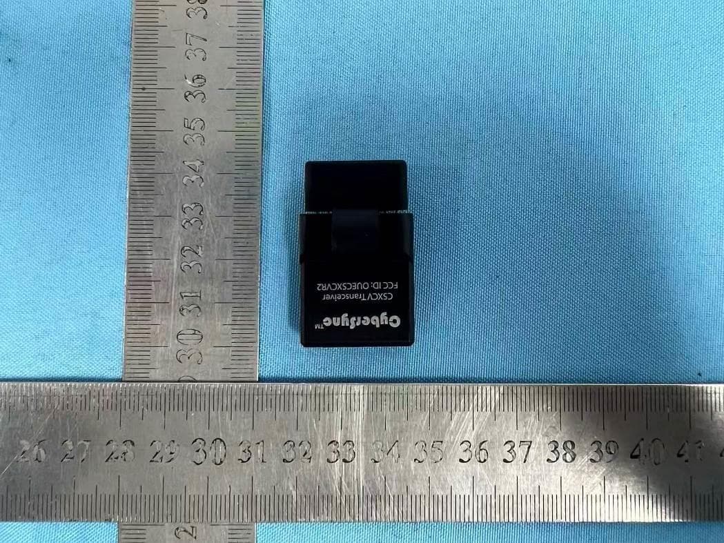
OUECSXCVR2
Dec 07, 2025CSXCV Transceiver
Equipment Class
JAB - Part 15 Class B Digital Device
OUECEL500
Apr 13, 2023Celestial
Equipment Class
JAB - Part 15 Class B Digital Device
OUECST3
Apr 28, 2022CST3
Equipment Class
DXX - Part 15 Low Power Communication Device Transmitter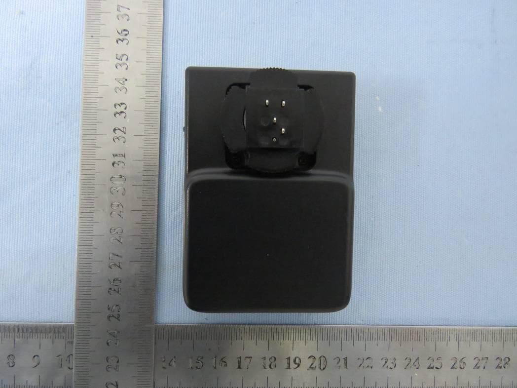
OUEPCBHUB
Mar 09, 2021HUB
Equipment Class
DXX - Part 15 Low Power Communication Device Transmitter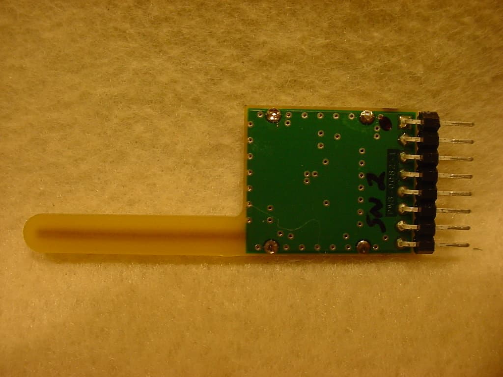
OUECSXCVR1
Apr 15, 2008CYBERSYNC TRANSCEIVER 1
Equipment Class
DXX - Part 15 Low Power Communication Device Transmitter