OUSCL1TC-4400-Watt, 1.6 GHz DVB-H Transmitter
UBS-Axcera
Click to zoom
Application Details
- Equipment Class
- TNB - Licensed Non-Broadcast Station Transmitter
- Date of Grant
- Sep 17, 2013
- Application Purpose
- Original Equipment
- Date of Application
- Sep 17, 2013
- Equipment Note
- 400-Watt, 1.6 GHz DVB-H Transmitter
- Frequency Range
- 1670.00000000 - 1675.00000000
- Company
- UBS-Axcera
- Country
- United States
Documents & Files
Document Text
Text extracted from the exhibit documents filed with the FCC. Open a document above to read the original.
Users Manual
Product Description CL1TC-4 Mobile Multimedia 400 Watt DVB-H L-Band Indoor/Outdoor Transmitter UBS-Axcera Inc. 103 Freedom Drive • P.O. Box 525 • Lawrence, PA 15055-0525, USA Phone: 724-873-8100 • Fax: 724-873-8105 www.UBS-Axcera.com • [email protected] NOTE: This equipment has been tested and found to comply with the limits for a Class A digital device, pursuant to part 15 of the FCC Rules. These limits are designed to pro-vide reasonable protection against harmful interference when the equipment is operated in a commercial environment. This equipment generates, uses, and can radiate radio frequency energy and, if not installed and used in accordance with the instruction manual, may cause harmful interference to radio communications. Operation of this equipment in a residential area is likely to cause harmful interference in which case the user will be required to correct the interference at his own expense. RESTRICTIONS ON USE, DUPLICATION OR DISCLOSURE OF PROPRIETARY INFORMATION This document contains information proprietary to UBS-Axcera, to its affiliates or to a third party to which UBS- Axcera may have a legal obligation to protect such information from unauthorized disclosure, use or duplication. Any disclosure, use or duplication of this document or any of the information herein for other than the specific purpose for which it was disclosed by UBS-Axcera is expressly prohibited, except as UBS-Axcera may otherwise agree in writing. Recipient by accepting this document agrees to the above stated conditional use of this document and this information disclosed herein. Copyright © 2012, UBS-Axcera CL1TC-4 400W DVB-H Transmitter Table of Contents Product Manual, Rev. 1 i 7/30/13 Table of Contents 1. Introduction ....................................................................................................1 1.1 Manual Overview ........................................................................................1 1.2 Safety .......................................................................................................1 1.3 Contact Information ....................................................................................2 1.4 Return Material Procedure ............................................................................2 1.5 Limited One Year Warranty for Axcera Products...............................................3 1.6 Warning ....................................................................................................4 1.7 Emergency First Aid Instructions ...................................................................5 1.8 Abbreviations/Acronyms ..............................................................................6 2 Product Description .........................................................................................7 2.1 Product Overview........................................................................................7 2.2 Cabinet Tour ..............................................................................................9 2.3 Product Architecture..................................................................................13 2.3.1 Transmitter Overview ..........................................................................13 2.3.2 UPS...................................................................................................13 2.3.3 Playout Server ....................................................................................13 2.3.4 Modulator ..........................................................................................15 2.3.4.1 DVB-H Modulator .........................................................................15 2.3.4.2 Amplifier ....................................................................................15 2.3.4.3 Bandpass Filter............................................................................16 2.3.4.4 GPS Receiver ..............................................................................16 2.3.4.5 I/O Extension Board.....................................................................16 2.3.4.6 Transmitter Controller Module .......................................................16 2.3.5 High Power Amplifier (HPA) ..................................................................18 2.3.5.1 HPA Enhanced Features and Design Concepts ..................................20 2.3.5.2 HPA Controller.............................................................................20 2.4 Breaker Panels .........................................................................................21 2.5 Control Interfaces .....................................................................................21 2.6 Remote Upgrades .....................................................................................22 3 Transmitter Technical Specifications .............................................................23 3.1 Modulation Standard .................................................................................23 3.2 Modulator Control Interfaces ......................................................................23 3.3 Modulator Inputs ......................................................................................23 3.4 Modulator Monitoring Outputs.....................................................................24 3.5 Modulator RF............................................................................................24 3.6 HPA Control Interfaces ..............................................................................25 3.7 HPA RF Input ...........................................................................................25 3.8 HPA/Transmitter RF Output ........................................................................25 3.9 Modulator Digital Pre-Correction .................................................................26 3.10 GPS ....................................................................................................…
Text truncated - open the document above for the full version.
Users Manual
CL1TC-4 400W DVB-H Transmitter WEB Interface Product Manual, Rev. 1 72 6.4.11 Site T he Site page allows the user to add information identifying the site, including the name of the site, address, contact information, etc. Each item is limited to 35 alphanumeric parameters. Figure 6-24 Site Information The available parameters are: Item Option System Description up to 35 alphanumeric characters Contact Information up to 35 alphanumeric characters System Location up to 35 alphanumeric characters Site Address Line 1 up to 35 alphanumeric characters Site Address Line 2 up to 35 alphanumeric characters Site Address Line 3 up to 35 alphanumeric characters Site Address Line 4 up to 35 alphanumeric characters Site Notes up to 35 alphanumeric characters Table 6-11 Site Parameters CL1TC-4 400W DVB-H Transmitter WEB Interface Product Manual, Rev. 1 73 6.5 Alarms Menu T he Alarms menu contains the following pull-down items (see Figure 6-25 below): • Alarm Properties • External Voltage Alarm Setting • Log Management • Alarm Log Figure 6-25 Alarms Menu The Alarms menu allows the user to set the properties of each alarm including system actions as well to view alarm and event logs. CL1TC-4 400W DVB-H Transmitter WEB Interface Product Manual, Rev. 1 74 6.5.1 Alarm Properties The fi rst item in the Alarm Properties page is the Alarm Index. The Alarm Index box has a pull-down menu permitting the user to select a specific alarm from the list for configuration. The list of alarms along with a description of each alarm can be found in Section 10 . The user can configure each alarm to be displayed (Alarm Enabled ON) or ignored (Alarm Enabled OFF) and can configure the modulator to send an SNMP trap for any active alarm. The user can also configure a number of relays on the modulator rear panel to be triggered on alarm. The integration time can be set to any value between 0 to 360 seconds, allowing the modulator to avoid reporting intermittent alarms. An alarm will only be reported if it is still active after the integration time has elapsed. The Alarm Properties page also summarizes the current Alarm Properties settings for all system alarms under Alarm Property Setting Summary. Figure 6-26 Alarm Properties Configuration CL1TC-4 400W DVB-H Transmitter WEB Interface Product Manual, Rev. 1 75 For each alarm, the user can set the following: Item Option Alarm Enabled OFF, ON Used to control whether the selected alarm will be displayed (ON) or ignored (OFF). Trap Notification on Alarm OFF, ON Used to control whether the selected alarm will produce a SNMP trap notification. Integration Time 0 to 360 sec Length of time an alarm condition is present before the alarm is declared. Mute on Alarm OFF, ON Used to control whether the selected alarm will mute the transmitter output. Relay on Alarm OFF, ON Used to control whether the selected alarm will active the first alarm relay. Second Relay on Alarm OFF, ON Used to control whether the selected alarm will active the second alarm relay. Alarm Severity Level Critical, Warning, Informative, Cleared Table 6-12 Alarm Properties Parameters CL1TC-4 400W DVB-H Transmitter WEB Interface Product Manual, Rev. 1 76 6.5.2 External Voltage Alarm Setting The External Voltage Alarm Setting page allows the user to set the voltage threshold for each of the I/O port analog inputs (pins). Voltage 1 though Voltage 8 correspond to pins 1 though 8; pin 9 is ground. For example, the pin 6 settings (Voltage6 Trigger Polarity and Voltage6 Trigger Threshold) seen in Figure 6-27 will create an alarm if the pin 6 output voltage is greater than 2.0 VDC. NOTE: For this application, Pin 6 has been connected to the cabinet door switch contacts, Pin 7 has been connected to the cabinet smoke detector and the Web interface has been configured accordingly. The External Voltage Alarm Settings should not be modifies by the user. Figure 6-27 External Voltage Alarm Setting Configuration For each I/O pin, the user can set the following: Item Selection Voltage Trigger Polarity <, > Voltage Trigger Threshold Range: 0.00 .. 10.00 Table 6-13 External Voltage Alarm Setting Parameters CL1TC-4 400W DVB-H Transmitter WEB Interface Product Manual, Rev. 1 77 6.5.3 Log Management The Log Management page can be used to clear the alarm log and/or event log, change the order alarms appear in the logs and change the displayed alarm log. If the Alarm Log is configured not to display alarms in reverse, the most recent alarm will be at the bottom of the list. If the Alarm Log is configured to display alarms in reverse, the most recent alarm will be at the top of the list. Figure 6-28 Log Management Configuration The available parameters are: Item Option Clear Alarm Log No, Yes Logs Display in Reverse No, Yes Used to determine the order alarms are displayed in the Alarm Log. Log To Display Transient Log, Alarm Log Used to determine if the Alarm Log will display Transient Alarms or Set Alarms. Table 6-14 Log Management Parameters CL1TC-4 400W DVB-H Transmitter WEB Interface Product Manual, Rev. 1 78 6.5.4 Alarm Log The Alarm Log lists the current alarms as well as all alarm log entries. Figure 6-29 Alarm Log Figure 6-30 Alarm Log (Log Displayed in Reverse) CL1TC-4 400W DVB-H Transmitter WEB Interface Product Manual, Rev. 1 79 6.6 NMS Users Menu The NMS Users menu includes the User Properties menu (see the pull down figure below). The NMS Users menu sets the parameters required for an individual user to establish communications with the modulator via a SNMP Network Management System (NMS). From the User Properties menu, each NMS user can be configured with a user name, password, Cryptographic Hash Function authentication type (SHA, MD5, none) and Data Encryption mode (DES, AES, none) plus encryption password. Figure 6-31 User Properties Configuration For each user, the following authorization parameters can be set. Item Option Username up to 35 alphanumeric characters Authorization Type SHA, Disabled, MD5 “Cryptographic Hash Functio…
Text truncated - open the document above for the full version.
External Photos
Photograph 1. Front View Photograph 2. Outdoor Cabinet Photograph 3. Rear View Photograph 4. Rear View Photograph 5. Transmitter Front View
ID Label/Location Info
Axcera-CL1TC-4 FCC Type Acceptance Report ID Label/Location Info August 2013 1-1 1.3 Rear view, complete Axcera-CL1TC-4 Transmitter with FCC Label and Manufacturer’s Label
Internal Photos
Photograph 1. Amplifier Bottom View Photograph 2. Amplifier Top View Photograph 3. Modulator Top View Photograph 4.
Parts List/Tune Up Info
31 10 22 1 4 13 19 7 18 25 8 24 29 27 28 1017 12 REAR PANEL SILK SCREEN DWG 56829-01 30 22 33 35 D A B C D 13 56 7 8 8 7 6 5 4 32 B SCALE SHEET OF PART # DOC. TYPE Q.A. WARNING, THIS DRAWING AND ITS CONTENTS ARE PROPERTY OF UNIQUE BROADBAND SYSTEMS INC, AND SHALL NOT BE CIRCULATED OR REPRODUCED WITHOUT THE WRITTEN PERMISSION OF UNIQUE BROADBAND SYSTEMS INC. 1:3.5 2 01 56803-43-D01-03 2 July-08-13 Univ. Mod DVB-H L-Band, with GPS, and additional I/O NIMAL.D 400 Spinnaker Way Vaugham, Ontario Canada, L4K 5Y9 Tel: (905) 669-8533 Fax (905) 669-8516 DWG. # REV. SIZE TITLE RESP ENG CHECKED DRAWN CAD GENERATED DRAWING DO NOT MANUALLY UPDATE OR SCALE DATE APPROVALS A B C 243 1 1 2 2 3 3 4 4 5 5 6 6 DD CC BB AA REV.DATEDESCRIPTIONECO#APPROVED Connector 3 pin 11 22 33 CON1 11913R GND RFI POWER LINE FILTER 13 G 24 FILTER FL1 80071 QTY NN UBS Number MFG N#MFG Description J1-3 J1-1 GND 75088R POWER SUPPLY, 60W, 5V,12V J1-4 J1-5 J1-1 J1-2 TP1 57662-01 Power Supply PCA L1 L1 L2(N) J1-4 J1-5 J1-1 J1-2 TP1 57662-01 Power Supply PCA L1 L1 75205R POWER SUPPLY, 30VDC, 1600W 75205R POWER SUPPLY, 30VDC, 1600W J10 J10 1 2 93024R 3081 BL005 Alpha Wire 10 AWG 600W PVC Blue 3 3 4 934769912 189 BELDEN 12AWG STR PVC 600V 105º Yel-Green 5 5 93019 9912 013 BELDEN 12AWG STR PVC 600V 105ó D BLUE 4 6 QTY NN UBS Number MFG N#MFG Description 7 93023R 3081 BR005 10 AWG 600W PVC Brown 3 8 93018 9912 001 BELDEN 12AWG STR PVC 600V 105º BROWN 4 9 10 11 L1 L2 GND (N) 277VAC, 30A, 2-pole, magn. circ.brk 1 2 3 4 CB1 80197R 208 AC 2phase 30A 10608R 26-03-4030 MOLEX .156" Pitch Crimp Terminal Housing 3pos 1 11538R 09-91-0500 MOLEX .156" Pitch Crimp Terminal Housing 5pos 2 UBS # 11538R UBS # 10608R UBS # 10658R UBS # 10658R 10658R 08-52-0072 MOLEX .156" Pitch Crimp Terminal,Female 13 16102R 2210.0 Altech Corporation Ferrule Insulated Std 10AWG Black 2 16101R 2402.0 Altech Corporation Ferrule Insulated Std 12AWG Gray 4 92795 9918 013 BELDEN 18AWG STR PVC 300V 105º D. Blue 1 L2(N) L2(N) L2(N) 12 Back Plate 10090R 19067-0008 MOLEX Ring Terminal1/4" for 8AWG Wire,Red 5 B C B A UBS # 92795 UBS # 93018 92794R 9918 001 BELDEN 18AWG STR PVC 300V 105º BROWN 1 13 Title Document Number Rev DATE Sheetof Drawn by: APPROVALS 1 B 4 400W L-Band HPA Wiring AC Diagram 05 59175-02-D01 05/15/2013 Approved by: Size 400 Spinnaker Way Vaughan, Ontario, Canada, L4K 5Y9 Tel: (905) 669-8533 Checked by: Kosta Bor UBS # 93024R UBS # 93023R GND GND Alpha Wire UBS # 92794R UBS # 93019 16423R 1 2 TB L1 1 2 1 2 1 2 1 2 16150R 1 2 TB GND 1 2 1 2 16423R 1 2 TB L1 16423R CTS4U-N Altech Corporation TERMINAL BLOCK 35A, DIN RAIL 6 14 16150R CGT4U TERMINAL BLOCK, 25A, DIN rail , GND 3 15 Altech Corporation 16321R CTS2.5U-N TERMINAL BLOCK, DIN RAIL 3 16 Altech Corporation 86185R CTS2.5U-N/R TERMINAL BLOCK, DIN RAIL, RED 3 17 Altech Corporation 86186R CTS2.5U-N/W TERMINAL BLOCK, DIN RAIL, White 3 18 Altech Corporation 3 22/07/2013 Changed copnnection HPA to Current Sense 4 24/07/2013 Removed connection 12VDC from Current Sense 2 26/06/2013 Removed small cooling fan 30VDC TB 1 To TB 2-19 Note 1: Recommended Hand Crimp Tool - 0638117500 for 0638117500 pins Recommended Hand Crimp Tool - 1212045 for ferrules Recommended Hand Crimp Tool - MAC 2210 for ring terminals 5 07/31/2013 Changed terminal connection PICB101 PICB102 PICB103 PICB104 COCB1 PICON101 PICON102 PICON103 COCON1 PIFL101 PIFL102 PIFL103 PIFL104 PIFL10G COFL1 PITB?01PITB?02 COTB? PITB?01PITB?02 PITB?01PITB?02 PITB?01PITB?02 PITB?01PITB?02 PITB?01PITB?02 PITB GND01PITB GND02 COTB GND PITB L101PITB L102 COTB L1 PICON103 PIFL10G PITB?01 PICB101PICON101 PICB102 PICON102 PICB103 PIFL101 PICB104 PIFL102 PICON101 PICON102 PICON103 PIFL103 PITB L101 PIFL104PITB L101 PITB?01 PITB?01 PITB?01 PITB?01 PITB?01 PITB?02 PITB?02 PITB?02 PITB?02 PITB?02 PITB?02 PITB GND01PITB GND02 PITB L102 PITB L102
Test Report
UBS-Axcera – CL1TC-4 Type Acceptance Report Test Report August 2013 4 - 1 4. TEST REPORT 4.1 RF Power Measurements Figure 4-1 shows the test equipment setup for the RF power measurements. All tests comply with FCC part 27 and part 2. Figure 4-1. Test Equipment Setup for RF Power Measurements The output power of the CL1TC-4 was adjusted to obtain 400 watts average RF output as observed on the power meter. With the power level properly set to 400 watts average, all required tests were performed and recorded in the following sections. Device Under Test UBS-Axcera DVU-5000 Modulator CL1TC-4 Transmitter Channel Filter Agilent CXA Signal Analyzer Agilent E4418B RF Power Meter Narda 3003-30 30 dB Directional Coupler Narda 3003-30 30 dB Directional Coupler 20 dB Attenuator 50 Ohm Termination UBS-Axcera – CL1TC-4 Type Acceptance Report Test Report August 2013 4 - 2 4.2 Modulation Characteristics The modulator tray incorporates a modulation technique known as COFDM, which uses 2000-8000 carriers, each one modulated with QAM or QPSK. The signal is noise-like in appearance and has a relatively stable average power and a widely varying peak- envelope-power (PEP). The power is normally referred to in average power. COFDM, used in conjunction with digital compression, provides high bandwidth efficiency. Figure 4-2. Typical Demodulation Test Setup Device Under Test UBS-Axcera DVU-5000 Modulator CL1TC-4 Transmitter Channel Filter Narda 3003-30 30 dB Directional Coupler 50 Ohm Termination Agilent CXA Signal Analyzer 20 dB Attenuator Laptop Computer UBS-Axcera – CL1TC-4 Type Acceptance Report Test Report August 2013 4 - 3 4.3 Occupied Bandwidth Using the test setup in Figure 4-4, with the transmitter operating at maximum power, photographs of the transmitter occupied bandwidth spectrum were taken and are shown in Figure 4-5. Figure 4-4. Test Setup for Occupied Bandwidth Spectrum Analysis Device Under Test UBS-Axcera DVU-5000 Modulator CL1TC-4 Transmitter Channel Filter Agilent CXA Signal Analyzer Agilent E4418B RF Power Meter Narda 3003-30 30 dB Directional Coupler Narda 3003-30 30 dB Directional Coupler 20 dB Attenuator 50 Ohm Termination UBS-Axcera – CL1TC-4 Type Acceptance Report Test Report August 2013 4 - 4 Figure 4-5. Channel Occupied Bandwidth (lower channel edge) UBS-Axcera – CL1TC-4 Type Acceptance Report Test Report August 2013 4 - 5 Figure 4-6. Channel Occupied Bandwidth (upper channel edge) UBS-Axcera – CL1TC-4 Type Acceptance Report Test Report August 2013 4 - 6 100W pre-filter 400W UBS-Axcera – CL1TC-4 Type Acceptance Report Test Report August 2013 4 - 7 100W 26dB points 400W UBS-Axcera – CL1TC-4 Type Acceptance Report Test Report August 2013 4 - 8 100W 20dB points UBS-Axcera – CL1TC-4 Type Acceptance Report Test Report August 2013 4 - 9 100W 20dB UBS-Axcera – CL1TC-4 Type Acceptance Report Test Report August 2013 4 - 10 400W pre-filter UBS-Axcera – CL1TC-4 Type Acceptance Report Test Report August 2013 4 - 11 400W 26dB points 1 UBS-Axcera – CL1TC-4 Type Acceptance Report Test Report August 2013 4 - 12 400W 26dB points UBS-Axcera – CL1TC-4 Type Acceptance Report Test Report August 2013 4 - 13 400W 20dB points 1 UBS-Axcera – CL1TC-4 Type Acceptance Report Test Report August 2013 4 - 14 400W 20dB points UBS-Axcera – CL1TC-4 Type Acceptance Report Test Report August 2013 4 - 15 4.4 Conducted Spurious Emissions Using the test setup shown in section 4.1, the spectrum outside of the specified channel was observed and the data was taken on all products above the -59 dB noise floor of the spectrum analyzer. Spurious Emissions were observed on the analyzer at a 2.900 GHz span (see spectrum plots on the following page). With the average in band signal set as the reference, the spurious emissions were observed. The measured data is shown in the table below for 400 watts (average) output power. This data is shown in Table 4-1 and is presented as graphs in Figure 4-7. Table 4-1. Products Above the -59 dB Noise Floor of the Spectrum Analyzer FREQUENCY (MHz) SOURCE PEAK LEVEL OBSERVED (dB) 1672.50 Center of Channel 0 dB (Reference) 36.00 IF Frequency None Observed 1708.50 Local Oscillator None Observed 3345.00 2 nd Harmonic None Observed 5017.50 3 rd Harmonic None Observed 6690.00 4 th Harmonic None Observed 8362.50 5 th Harmonic None Observed 10035.00 6 th Harmonic None Observed 11707.50 7 th Harmonic None Observed 13380.00 8 th Harmonic None Observed 15052.50 9 th Harmonic None Observed 16725.00 10 th Harmonic None Observed Complies with FCC Part 27 UBS-Axcera – CL1TC-4 Type Acceptance Report Test Report August 2013 4 - 16 Figure 4-7. Products Above the -59 dB Noise Floor of the Spectrum Analyzer (2.900 GHz Span) UBS-Axcera – CL1TC-4 Type Acceptance Report Test Report August 2013 4 - 17 Figure 4-8. Conducted Spurious Emissions (before channel filter) UBS-Axcera – CL1TC-4 Type Acceptance Report Test Report August 2013 4 - 18 Figure 4-9. Conducted Spurious Emissions (after channel filter) UBS-Axcera – CL1TC-4 Type Acceptance Report Test Report August 2013 4 - 19 Part 27.53 of the Rules states: (i) For operations in the 1670-1675 MHz band, the power of any emission outside the licensee's frequency band(s) of operation shall be attenuated below the transmitter power (P) by at least 43 + 10 log (P) dB. Compliance with these provisions is based on the procedures described in paragraph (a)(4) of this section. (a)(4) Compliance with these provisions is based on the use of measurement instrumentation employing a resolution bandwidth of 1 MHz or less, but at least one percent of the emission bandwidth of the fundamental emission of the transmitter, provided the measured energy is integrated over a 1 MHz bandwidth. Applying the formula above, the maximum amount of out-of-band power in a 1MHz bandwidth relative to the transmitter power can be calculated: 400W Transmitter: 43 +10*log(400)=69 dB. The performance of the Mask Filter was measured, and data was generated for its attenuation vs. frequency. This attenuation …
Text truncated - open the document above for the full version.
Contact Information
Applicant
David Hewitt(Engineering Manager)
Technical Contact
UBS-Axcera IncTom Botwright
[email protected]724-873-8100
103 Freedom Drive · Lawrence, Pennsylvania · United States
Technical Specifications
| # | Rule Parts | Frequency Range | Power Output | Emission | Tolerance |
|---|---|---|---|---|---|
| 1 | 27 | 1.67 GHz - 1.68 GHz | 400 W | 5M00W7D | 1672.5000000000 Hz |
Other Applications from UBS-Axcera

OUSCU0TD-5-UBS
Mar 27, 2014200W UHF Digital Transmitter
Equipment Class
TBC - Licensed Broadcast Station Transmitter
OUSCLV2TD-4
Aug 22, 2013Low Band VHF Digital Broadcast Transmitter
Equipment Class
TBC - Licensed Broadcast Station Transmitter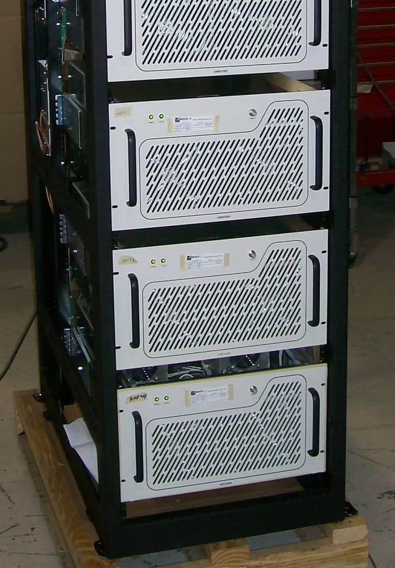
OUSCHV4TD
Jun 14, 20123000-Watt VHF Digital Transmitter
Equipment Class
TBC - Licensed Broadcast Station Transmitter
OUSCU0TD-5
Dec 14, 2011200 Watt UHF Digital Transmitter
Equipment Class
TBC - Licensed Broadcast Station Transmitter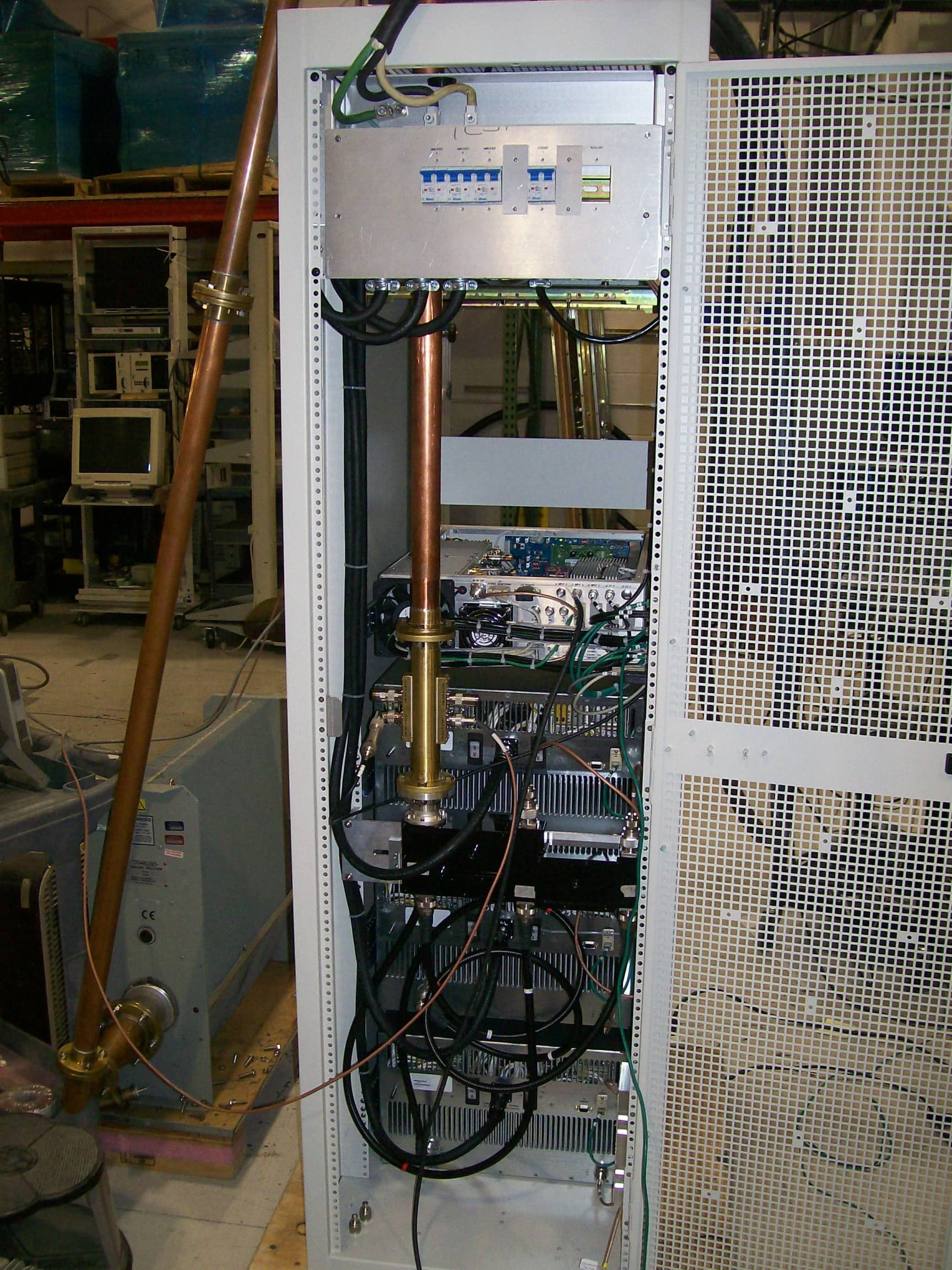
OUSCU3TD
Dec 14, 20112500 Watt UHF Digital Transmitter
Equipment Class
TBC - Licensed Broadcast Station Transmitter