OVO-LT2SPULeakTrac 2200
Analog Technologies Corp.
Click to zoom
Application Details
- Equipment Class
- DXX - Part 15 Low Power Communication Device Transmitter
- Date of Grant
- Apr 16, 2001
- Application Purpose
- Original Equipment
- Date of Application
- Apr 16, 2001
- Equipment Note
- LeakTrac 2200
- Frequency Range
- 916.50000000 - 916.50000000
- Company
- Analog Technologies Corp.
- Country
- United States
Documents & Files
Document Text
Text extracted from the exhibit documents filed with the FCC. Open a document above to read the original.
Users Manual
LeakTrac 2200 Operators Manual Draft Copy 3/26/2001 ANDERSON MANUFACTURING COMPANY, INC. 2885 Country Drive #190, St. Paul, MN 55117 (651) 484-1316 Fax (651) 484-0930
Attestation Statements
TÜV MANAGEMENT SERVICEPhone: (651) 631 2487 TÜV PRODUCT SERVICE INC.Fax: (651) 638 0285 1775 Old Highway 8 NW, Suite 104email [email protected] New Brighton MN 55112-1891http:://www.tuvglobal.com Divisions of TÜV America Inc., a subsidiary of TÜV Süddeutschland and TÜV Nord Group TÜV PRODUCT SERVICE INC 19333 WILD MOUNTAIN ROAD TAYLORS FALLS, MINNESOTA 55084-1786 ENGINEERING STATEMENT For Certification of Analog Technologies Corporation Wireless Signal Processing Unit (SPU) – Wireless Pool Leak Detector Transmitter Model No: LT2200 (P/N LT2SPU) I am an Electromagnetic Compatibility Engineer for TÜV PRODUCT SERVICE INC, Taylors Falls, Minnesota. My education and experience are a matter of record with the Federal Communications Commission. TÜV PRODUCT SERVICE INC has been authorized by William C. Berg, President, of Analog Technologies Corp., to make Certification measurements on the Wireless Signal Processing Unit (SPU) – Wireless Pool Leak Detector Transmitter. These tests were made by me or under my supervision at our Wild River Laboratory which is on file with the FCC under Paragraph 2.948 of the FCC Rules. Test data required by the TCB is included in this report. It is submitted that the above equipment meets the FCC Part 15, Subpart C Section 15.249 Requirements and Certification is hereby requested. Joel T. Schneider Chief Engineer Minnesota Wild River Lab TÜV Product Service [email protected] Dated: 26 March 2001
Block Diagram
SHEET: CHECKED BY: PART NUMBER: DRAWN BY: WC Berg 80 REVISION: CONFIDENTIAL Analog Technologies Corp. DATE: A 1/1 10 Hz Oscillator Amplfier MUltiplierIntegrator OOK Modulator 916.5 MHz Oscilla Transmitter Variable Audio Oscillator Speaker Probe Input TITLE: Wireless SPU Block Diagram 2/22/01
Cover Letter(s)
March 27, 2001 TCB BABT Product Service 4855 Patrick Henry Drive, Building 6 Santa Clara, CA 95054 Dear Sir or Madam: We, (Analog Technologies Corp. of 11441 Rupp Drive, Burnsville, MN 55337), hereby authorize TÜV Product Service (19333 Wild Mountain Road, Taylors Falls, MN 55084, Tel. (651) 583-3322) to act as our agent in all matters relating to applications for equipment authorization, including the signing of all documents relating to these matters. I further certify that the applicant nor any party to the application is subject to a denial of Federal benefits, that includes FCC benefits, pursuant to Section 5301 of the Anti-Drug Abuse Act of 1988, 21 U.S.C. Section 862. This authorization expires on March 27, 2002. Sincerely, William C. Berg President Phone: (952) 894-9228 Fax: (952) 894-2966 Analog Technologies Corp. 11441 Rupp Drive • Burnsville, MN 55337 • Phone (952) 894-9228 • FAX (952) 894-2966 April13, 2001 TCB Examiner or Certifier: I request that all schematics and Bill of Materials of the Wireless LeakTrac model 2200 Signal Processing Unit (SPU) supplied with our application for certification be withheld from public disclosure. These supplied files are: SPU_Schematic.pdf SPU_BOM.pdf This request is made pursuant to Sections 0.457 and 0.459 of FCC rules. Analog Technologies Corp. has a significant engineering investment and regards this information as confidential. Disclosure to potential competitors may cause us irreparable harm. Respectfully, William C. Berg President Analog Technologies Corp. 11441 Rupp Drive • Burnsville, MN 55337 • Phone (952) 894-9228 • FAX (952) 894-2966
External Photos
Side 1 Side 2 SPU BP SPU Bottom SPU FP
ID Label/Location Info
Location bottom Content
Internal Photos
SPU Interface1 SPU Interface 2 SPU Interface 3 SPU interface 4 SPU Main SPU Main 2 SPU Main 3 SPU Main bottom SPU Main with Transmitter SPU transmitter SPU XMTR bottom SPU
Operational Description
Operational Description For LT2200 Wireless Signal Processing Unit (SPU) Block Diagram Description The LT2200 Signal Processing unit (SPU) is comprised of the following circuit blocks: 10 Hz oscillator Correlator (multiplier and integrator Variable audio oscillator driving a speaker Input signal amplifier 916.5 MHz OOK modulated transmitter A 10 Hz square wave oscillator simultaneously drives a multiplier and modulates the RF transmitter. This oscillator On-Off modulates a 916.5 MHz (On OFF Keyeing, OOK) carrier. The multiplier along with a f ollowing integrator stage forms a correlator which correlates the the 10 Hz square wave to the amplified input signal. A DC voltage results from correlating the 10 Hz square wave from the amplified input signal. The amplifier has a bandwidth of 300 Hz. The higher the correlation, the higher the voltage. This voltage is used to control a variable frequency audio oscillator. The frequency of the oscillator rises with increasing correlation. The frequency will diminish with decreasing correlation and oscillator will turn off with negative correlation. The audio oscillator frequency can range from “OFF” to about 1 KHz. 916.5 MHz Transmitter Description The 916.5 MHz transmitter is based on a Colpitts type, single transistor oscillator. The frequency is controlled by a 916.5 MHz +/- 100KHz, single port SAW resonator. A 10 Hz square wave,.with a maximum duty cycle of 50%, signal is presented to the base of the transistor. The oscillator will turn off when the transistor’s base voltage falls below the cut-off voltage and turns on when rising above the cut-off voltage. A 3.3 volt regulator stabilizes the transistor’s operation. The oscillator was design for a maximum output power of 0 dBm yielding a 50mV/meter field strength at 3 meters. The transmitter’s antenna is incorporated into the printed circuit board. It is a quarter wavelength monopole. No tuning is required for this transmitter.
RF Exposure Info
TCB Declaration of Compliance to RF Exposure Limits for Humans The LT2200 Wireless Pool Leak Detector Transmitter complies with the RF exposure limits for humans as called out in 2.1093. It is used by an operator to detect leaks in a swimming pool, so it is considered to be a portable device by definition. It is exempt from RF evaluation based on its operating frequency of 916.3 MHz, and output power of 407 microwatts based on TP = (FS x D) 2 / 30 x 1.65, (47315 uV/m x 3) 2 / 30 x 1.65. This would be less than the 200 milliwatt requirement for portable devices. Joel T Schneider TUV Product Service
Test Report
PRODUCT SERVICE TEST RESULT SUMMARY FCC PART 15 Subpart C Section 15.249 MANUFACTURER'S NAMEAnalog Technologies Corporation NAME OF EQUIPMENTWireless Signal Processing Unit (SPU) - Wireless Pool Leak Detector Transmitter MODEL NUMBER LT2200 (P/N LT2SPU) MANUFACTURER'S ADDRESS11441 Rupp Drive Burnsville MN 55345 TEST REPORT NUMBERW1064 TEST DATE02 & 14 February 2001 According to testing performed at TÜV Product Service Inc, the above-mentioned unit is in compliance with the electromagnetic compatibility requirements defined in FCC Part 15 Subpart C Section 15.249. It is the manufacturer's responsibility to assure that additional production units of this model are manufactured with identical electrical and mechanical characteristics. Any modifications necessary for compliance made during testing on the above mentioned date(s) must be implemented in all production units for compliance to be maintained. TÜV Product Service Inc, as an independent testing laboratory, declares that the equipment tested as specified above conforms to the requirements of FCC Part 15 Subpart C Section 15.249. Date:08 March 2001 Location:Taylors Falls MNJ. C. SausenJ. T. Schneider USATest EngineerChief Engineer Not Transferable File No. WC1G106401, Page 1 of 11 TÜV PRODUCT SERVICE INC19333 Wild Mountain RoadTaylors Falls MN 55084-1758Tel: 651 638 0297Fax: 651 638 0298Rev.No 1.0 PRODUCT SERVICE EMC EMISSION - T E S T R E P O R T Test Report File No.: WC1G106401 Date of issue: 08 March 2001 Model / Serial No.: LT2200 (P/N LT2SPU) / 001 Product Type: Wireless Signal Processing Unit (SPU) - Wireless Pool Leak Detector Transmitter Applicant: Analog Technologies Corporation Manufacturer: Analog Technologies Corporation License holder: Analog Technologies Corporation Address: 11441 Rupp Drive : Burnsville MN 55345 Test Result: nn Positiveoo Negative Test Project Number: Reference(s) W1064 Total pages including Appendices 26 TÜV Product Service Inc is a subcontractor to TÜV Product Service, GmbH according to the principles outlined in ISO/IEC Guide 25 and EN 45001. TÜV Product Service Inc reports apply only to the specific samples tested under stated test conditions. It is the manufacturer's responsibility to assure that additional production units of this model are manufactured with identical electrical and mechanical components. TÜV Product Service Inc shall have no liability for any deductions, inferences or generalizations drawn by the client or others from TÜV Product Service Inc issued reports. This report is the confidential property of the client. As a mutual protection to our clients, the public and ourselves, extracts from the test report shall not be reproduced except in full without our written approval. This report shall not be used by the client to claim product endorsement by NVLAP or any agency of the US government. TÜV Product Service Inc and its professional staff hold government and professional organization certifications and are members of AAMI, ACIL, AEA, ANSI, IEEE, NVLAP, and VCCI File No. WC1G106401, Page 2 of 11 TÜV PRODUCT SERVICE INC19333 Wild Mountain RoadTaylors Falls MN 55084-1758Tel: 651 638 0297Fax: 651 638 0298Rev.No 1.0 PRODUCT SERVICE D I R E C T O R Y - EMISSIONS Page(s) A)Documentation Test report1 - 10 Directory2 Test Regulations3 Deviation from standard / Summary10 Test-setups (Photos)11 Test-setup (drawing)Appendix A B)Test data Conducted emissions10/150 kHz - 30 MHz5, 9 Radiated emissions10 kHz - 30 MHz5, 9 Radiated emissions30 MHz - 1000 MHz6, 9 Interference power30 MHz - 300 MHz6, 9 Equivalent Radiated emissions1 GHz - 10 GHz7, 9 C)Appendix A Test Data Sheets and Test Setup Drawing(s) A2 – A6 D)Appendix B Constructional Data Form B2 – B7 Product Information Form(s) N/A E)Appendix C Measurement ProtocolC1 - C2 File No. WC1G106401, Page 3 of 11 TÜV PRODUCT SERVICE INC19333 Wild Mountain RoadTaylors Falls MN 55084-1758Tel: 651 638 0297Fax: 651 638 0298Rev.No 1.0 PRODUCT SERVICE EMISSIONS TEST REGULATIONS : The emissions tests were performed according to following regulations: -------------------------------------------------------------------------------- o - EN 50081-1 / 1991 o - EN 55011 / 1991o - Group 1o - Group 2 o - Class Ao - Class B o - EN 55013 / 1990 o - EN 55014 / 1987o - Household appliances and similar o - Portable tools o - Semiconductor devices o - EN 55014 / A2:1990 o - EN 55014 / 1993o - Household appliances and similar o - Portable tools o - Semiconductor devices o - EN 55015 / 1987 o - EN 55015 / A1:1990 o - EN 55015 / 1993 o - EN 55022 / 1987o - Class Ao - Class B o - EN 55022 / 1994o - Class Ao - Class B o - BS o - VCCIo - Class Ao - Class B n - FCC Part 15 Subpart C Section 15.249 o - AS 3548 (1992)o - Class Ao - Class B o - CISPR 11 (1990) o - Group 1o - Group 2 o - Class Ao - Class B o - CISPR 22 (1993) o - Class Ao - Class B o - RSS-210 Issue 2 Rev. 1 Section 6.1.1 & 7.0 File No. WC1G106401, Page 4 of 11 TÜV PRODUCT SERVICE INC19333 Wild Mountain RoadTaylors Falls MN 55084-1758Tel: 651 638 0297Fax: 651 638 0298Rev.No 1.0 PRODUCT SERVICE Environmental conditions in the lab: Actual Temperature: 18 °C Relative Humidity: 24 % Atmospheric pressure: 99.5 kPa Power supply system: 18 VDC (2 9V Batteries) Sign Explanations: o - not applicable n - applicable File No. WC1G106401, Page 5 of 11 TÜV PRODUCT SERVICE INC19333 Wild Mountain RoadTaylors Falls MN 55084-1758Tel: 651 638 0297Fax: 651 638 0298Rev.No 1.0 PRODUCT SERVICE Emissions Test Conditions: CONDUCTED EMISSIONS (Interference Voltage) The CONDUCTED EMISSIONS (INTERFERENCE VOLTAGE) measurements were performed at the following test location: n - Test not applicable o - Wild River Lab Large Test Site (Open Area Test Site) o - Wild River Lab Small Test Site (Open Area Test Site) o - Oakwood Lab (Open Area Test Site) o - Wild River Lab Screen Room o - New Brighton Lab Shielded Room Test equipment used : Emissions Test Conditions: RADIATED EMISSIONS (Magnetic Field) The RADIATED EMISSIONS (MAGNETIC FIELD) measuremen…
Text truncated - open the document above for the full version.
Test Setup Photos
File No. W101574001, Page A2 of A9 EMM0094 REV 09.95 TEST SETUP FOR EMISSIONS TESTING WILD RIVER LAB Large Test Site Notes: 1.Items shown in dotted lines are located on the floor below the test area. It is 5 meters vertically from the ground floor to the test area. 2.50 Hz, 60 Hz, and 400 Hz are power panels for alternating current. 3.The antenna may be positioned horizontally 3, 10 or 30 meters from the center of the turntable. 4.The circle is a 6.7 meter diameter turntable. 5.A ground plane is in the plane of this sheet. 6.The test sample is shown in the azimuthal position representing zero degrees. EUT 0 90270 180 60 Hz 50 Hz 400 Hz Shielded Enclosure ANTENNA
Contact Information
Applicant
William C Berg(President)
Test Firm
TUV SUD America - Product ServiceJoel Schneider
Technical Specifications
| # | Rule Parts | Frequency Range | Power Output | Tolerance |
|---|---|---|---|---|
| 1 | 15C | 916.5 MHz - 916.5 MHz | 407.00 µW | 0.0110000000 % |
Other Applications from Analog Technologies Corp.

OVO-759R
Mar 22, 2000916.5 MHz Receiver
Equipment Class
CYY - Communications Receiver used w/Pt 15 Transmitter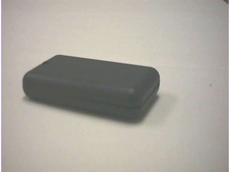
OVO758T
Mar 19, 2000916.5 Mhz Transmitter
Equipment Class
DSC - Part 15 Security/Remote Control Transmitter