OVO758T916.5 Mhz Transmitter
Analog Technologies Corp.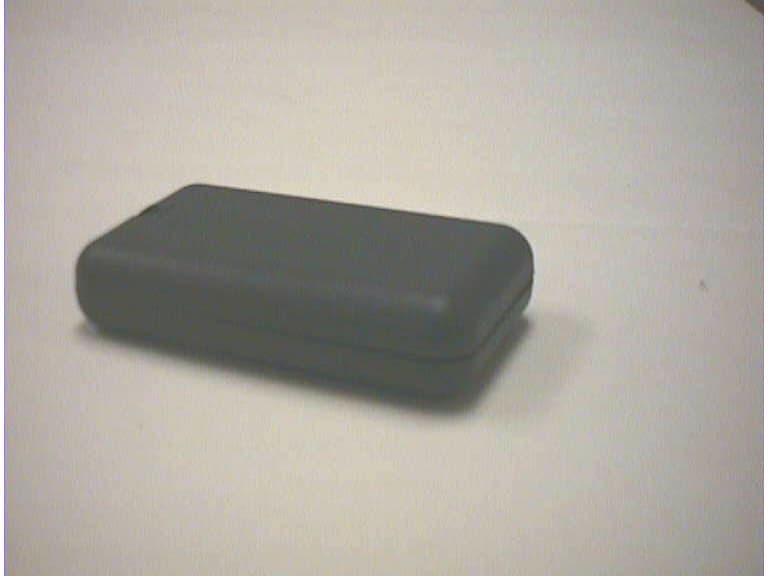
Click to zoom
Application Details
- Equipment Class
- DSC - Part 15 Security/Remote Control Transmitter
- Date of Grant
- Mar 19, 2000
- Application Purpose
- Original Equipment
- Date of Application
- Feb 04, 2000
- Equipment Note
- 916.5 Mhz Transmitter
- Frequency Range
- 916.50000000 - 916.50000000
- Company
- Analog Technologies Corp.
- Country
- United States
Documents & Files
Document Text
Text extracted from the exhibit documents filed with the FCC. Open a document above to read the original.
Users Manual
International Certification Services, Inc. HFS 300-S Operations Manual There is no operations manual for the transmitter because it is simply a sub assembly for other top level assemblies.
Users Manual
International Certification Services, Inc. 916.5 Mhz Transmitter Operations Manual There is no operations manual for the transmitter because it is simply a sub assembly for other top level assemblies.
Block Diagram
International Certification Services, Inc. 916.5 Mhz Hybrid Transmitter chip Built-in Internal Loo p Antenna 900 Mhz Dynamic Alarms Transmitter Block Diagram Micro-processor 32.768 Khz crystal Encoder DIP switch 2 BR-1225 batteries
Cover Letter(s)
1100 Falcon Ave.Tele:320-864-4444 Glencoe, MN 55336 Fax:320-864-6611 “Your Agent to Product Certifications and Licenses Throughout the World” To:FCCFeb 6, 2000 From: Duane R. Bagdons Form 731 Conf No. EA96713, FCC ID #OVO758T I mistakenly sent the wrong operations manual file with the submission that I did yesterday. I am replacing it with the following attachment sent today. Please remove the previouos operations manual and replace it with this new file. Thank you Duane R. Bagdons INTERNATIONAL CERTIFICATION SERVICES INC.
External Photos
International Certification Services, Inc. 900 Mhz Transmitter Top Level Assembly External Photos
ID Label/Location Info
International Certification Services, Inc. Analog Technologies Corp. 916.5 Mhz Transmitter Label Information FCC ID: OVO-758T This device complies with Part 15 of the FCC Rules. Operation is subject to the following two conditions: (1) this device may not cause harmful interference, and (2) this device must accept any interference received, including interference that may cause undesired operation. DYNAMIC ALARMS, INC. Brainerd, MN 56401 International Certification Services, Inc. Analog Technologies Corp 916.5 Mhz Transmitter ID Label
Internal Photos
International Certification Services, Inc. Internal Photos 900 Mhz Transmitter PC Board Internal built in Loop Antenna International Certification Services, Inc. Internal Photos 900 Mhz Transmitter PC Board Transmitter chip 32.768 Khz Crystal Encoding DIP Switch Internal Battery Source
Operational Description
International Certification Services, Inc. 916.5 Mhz Transmitter Operation Description The 2 coin cell powered transmitter is an intentional radiator using OOK modulation operating at 916.5 Mhz. It is based on the HX2000 Hybrid transmitter from RF Monolithics. The part has a typical output power of 0 dBm. The transmitter assembly contains a small modified monopole antenna with a typical loss of 6 to 10 dB. This translates to approximately less than 50 mV / Meter at 3 meters. The transmitter does not operate continuously. When sensing a disturbance, it will transmit for 7 to 10 seconds before shutting OFF. If a disturbance continues, it will remain OFF until the disturbance is removed for at least 30 seconds.
Schematics
International Certification Services, Inc. 900 Mhz Transmitter Electrical Schematic
Test Report
TEST REPORT #300699 STANDARD: FCC PART 15 SUBPART C--INTENTIONAL RADIATORS SECTION 15.231 PERIODIC OPERATION IN THE BAND 40.66-40.70 MHZ AND ABOVE 70 MHZ. EQUIPMENT TESTED: ANALOG TECHNOLOGIES CORP MODEL: 916.5 MHZ TRANSMITTER TEST DATE: 30 JUNE 1999 INTERNATIONAL CERTIFICATION SERVICES, INC. 1100 Falcon Avenue Glencoe, MN 55336 Tele: 320-864-4444 Fax: 320-864-6611 INTERNATIONAL CERTIFICATION SERVICES, INC. Prepared for: Test agent: Test location: Prepared by: . Analog Technologies, Corp. 12140 12 th Avenue South Burnsville, MN 55337 International Certification Services, Inc. 1100 Falcon Avenue Glencoe, MN 55336 Tele: 320-864-4444 Fax: 320-864-6611 International Certification Services, Inc. 1100 Falcon Avenue Glencoe, MN 55336 Tele: 320-864-4444 Fax: 320-864-6611 International Certification Services, Inc. 1100 Falcon Avenue Glencoe, MN 55336 International Certification Services represents to the client that testing is done in accordance with standard procedures applicable and that reported test results are accurate within generally accepted commercial ranges of accuracy. This report only applies to the specific samples tested under stated test conditions. It is the manufacturer’s responsibility to assure that additional production units of this model are manufactured with identical electrical and mechanical components. International Certification Services shall have no liability for any deductions, inferences or generalizations drawn by the client or others from this report. This report is the confidential property of the client. As a mutual protection to our clients, the public and ourselves, extracts from the test report shall not be reproduced except in full without our written approval. INTERNATIONAL CERTIFICATION SERVICES, INC. 1.0 TEST SUMMARY TEST REPORT: #300699 COMPANY: AGENT:International Certification Services, Inc. PHONE:320-864-4444 TEST DATE: EQUIPMENT UNDER TEST: GENERAL TEST SUMMARY: VERIFICATION / CERTIFICATION STATUS: MODIFICATIONS NECESSARY: TESTED BYWRITTEN BY Gerald HeinenDuane R. Bagdons Analog Technologies, Corp 30 June, 1999 916.5 Mhz Hand Held battery powered Intentional Radiator. The testing was performed at International Certification Services, Inc. at 1100 Falcon Ave, Glencoe, MN 55336 The 916.5 Mhz Transmitter was found to be in compliance with the FCC Part 15 Subpart C, Section 15.231 requirements. None INTERNATIONAL CERTIFICATION SERVICES, INC. Applicable Standards 47 CFR Ch.1 (10-1-98 Edition) FCC Part 15Radio Frequency Devices Subpart CIntentional Radiators Section 15.231 Periodic operation in the band 40.66-40.70 Mhz and above 70 Mhz. 2.1Referenced Standards ANSI C63.4-1992Methods of Measurement of Radio-Noise Emissions from Low- Voltage Electrical and Electronic Equipment in the Range of 9 Khz to 40 Ghz. 2.2 Equipment Units Tested The equipment tested was a 916.5 Mhz ON-OFF KEYED (OOK) modulated hand held battery powered transmitter. This device is a hand held unit with no attached cables or protruding antenna. The antenna is a permanent component and is part of the internal PC board assembly. The unit is programmed to transmit a burst of OOK modulated signal of 35 mS when activated. This device is used as an alarm signal transmitter. When a disturbance is sensed, it will automatically transmitt this above burst for 7 to 10 seconds before automatically shutting OFF. If a disturbance continues, it will remain OFF until the disturbance is removed for at least 30 seconds. This timing is controlled by firmware in the internal microprocessor. 2.3 Equipment and Cable Configuration See photos of the EUT pc board and schematic and test configuration setup in Attachment A 2.4 List of Test Equipment Measurement cable losses, and antenna correction factors are included in the data sheets. Average detection methods were used in the measurements. The Resolution BW was set at 1 Mhz and the Video BW was set at 1 Hz with a Span of 0 Hz to perform the correct average detected measurements. Test Equipment Spectrum Analyzer Preamp Biconical Antenna Log Periodic Antenna (200-1000 MHz) Horn Antenna (1-18 Ghz) Model Hewlett-Packard 8566B MiniCircuits ZKL-2R7 AH Systems Model SAS- 200/540 EMCO 3146 EMCO 3115 S/N 2421A00458 N/A 328 9111-3280 5697 Calibration Date 3/10/99 6/1/99 6/16/99 6/16/99 3/5/99 INTERNATIONAL CERTIFICATION SERVICES, INC. 2.5 Units of Measurement. All measurements were taken in dBuV/m with the antenna located at 3 meters distance from the EUT. Frequency measurements are recorded in Mhz. Input power to the intentional radiator was not recorded---only the radiated emissions with the internal transmitting antenna were recorded. 2.6 Location of Test Site The open area test site (OATS) measurement facility used to collect the data was International Certification Services, Inc. at 1100 Falcon Ave in Glencoe, MN 55336. This site has been certified to be in spec of the normalized site attenuation per ANSI C63.4-1992. See letter of compliance from FCC dated July 23, 1998. (FCC 31040/SIT 1300F2) 2.7 Measurement Procedures The antenna was placed at a distance of 3 meters from the EUT. The EUT was set on an insulating table in the OATS site and rotated through 360 degrees to determine the worst case EUT orientation. The antenna was then positioned vertical and horizontal to determine which antenna polarity orientation was worst case. Then certification data was recorded at all the transmitter frequencies from the fundamental to the 10 th harmonic at an antenna height variation of from 1-4 meters. 2.8Reporting Measurement Data See data sheets and plots in Attachment B. 2.9Radiated Emissions Data The frequency and amplitude of the tuned frequency of the EUT along with the frequencies and amplitudes of the harmonics up to the 5 th harmonic are reported in the data sheets in Attachment B. Signal frequencies above 5499.598 Mhz were below the noise floor of the measurement system. This information is plotted against the limit of section 15.231 of FCC Part 15 subpart C. Both…
Text truncated - open the document above for the full version.
Test Setup Photos
International Certification Services, Inc. 900 Mhz Transmitter Radiated Emissions Test Configuration
Contact Information
Applicant
William C Berg(President)
Test Firm
International Certification Services Inc.Duane Bagdons
Technical Specifications
| # | Rule Parts | Frequency Range | Power Output |
|---|---|---|---|
| 1 | 15C | 916.5 MHz - 916.5 MHz | - |
Other Applications from Analog Technologies Corp.

OVO-LT2SPU
Apr 16, 2001LeakTrac 2200
Equipment Class
DXX - Part 15 Low Power Communication Device Transmitter
OVO-759R
Mar 22, 2000916.5 MHz Receiver
Equipment Class
CYY - Communications Receiver used w/Pt 15 Transmitter