OVPRX600-840CKangaroo CaddieCommand Radio Receiver
Kangaroo Products Company
Click to zoom
Application Details
- Equipment Class
- CYY - Communications Receiver used w/Pt 15 Transmitter
- Date of Grant
- Mar 06, 2000
- Application Purpose
- Original Equipment
- Date of Application
- Feb 08, 2000
- Equipment Note
- Kangaroo CaddieCommand Radio Receiver
- Frequency Range
- 903.37000000 - 921.37000000
- Company
- Kangaroo Products Company
- Country
- United States
Documents & Files
Document Text
Text extracted from the exhibit documents filed with the FCC. Open a document above to read the original.
ID Label/Location Info
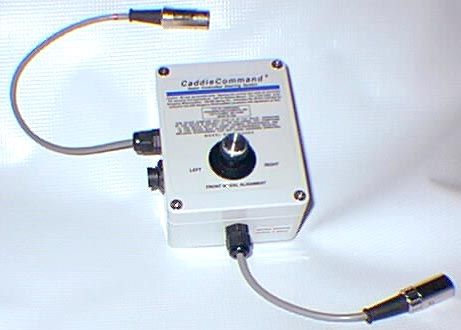
CaddieCommand ® Radio Controlled Steering System Caution: No user serviceable parts. Opening this receiver box voids all warranties. For warranty and instructions, refer to Owner’s Manual. (For a free copy, write Kangaroo Motorcaddies, 108 Mill Spring Rd., Columbus NC 28722.) Intended for exclusive use with Kangaroo Motorcaddies consistent with Agreement of Sale. FCC ID: OVPRX600-840C KANGAROO PRODUCTS CO. COLUMBUS, NC 28722 MADE IN USA THIS DEVICE COMPLIES WITH PART 15 OF FCC RULES. OPERATION OF THIS DEVICE IS SUBJECT TO THE FOLLOWING TWO CONDITIONS: (1) THIS DEVICE MAY NOT CAUSE HARMFUL INTERFERENCE, AND (2) THIS DEVICE MUST ACCEPT ANY INTERFERENCE RECEIVED, INCLUDING INTERFERENCE THAT MAY CAUSE UNDESIRED OPERATION. M O D E L N O . R X 6 0 0 - 8 4 0 C LEFT RIGHT FRONT WHEEL ALIGNMENT
Operational Description
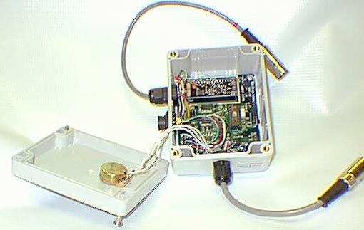
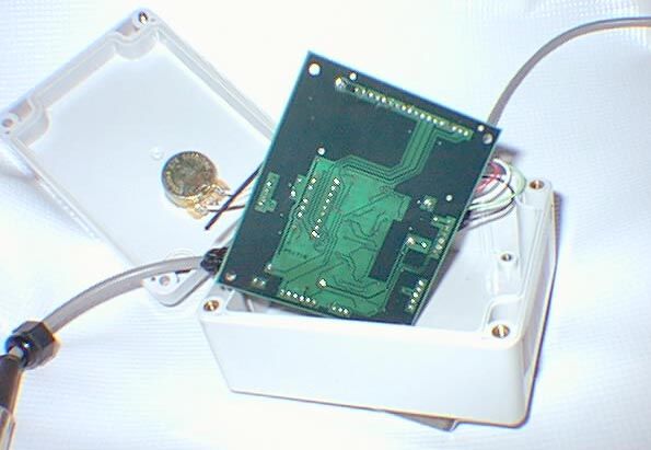
Description of Kangaroo Products Company Receiver Model RX600-840C FCC ID OVPRX600-840C Form 731 Confirmation Number EA96739 The receiver is a device used to control a motorized golf caddie, used exclusively on golf courses. A companion handheld transmitter is used by a golfer to send four commands to the caddie: stop, go, turn left, and turn right. Please refer to the schematic and block diagram of the receiver. The receiver is controlled by a Microchip PIC series microprocessor running on a 3.58MHz ceramic resonator, U4 on the schematic. Radio reception is accomplished through the use of a Linx Technoligies module, model number RXM-900-HP-II, U1 on the schematic. This module tunes eight channels, binary selectable using three digital logic inputs: 903.37MHz 906.37MHz 907.87MHz 909.37MHz 912.37MHz 915.37MHz 919.87MHz 921.37MHz The microprocessor controls two of the three channel selection lines directly, with the third being set using a solder jumper on the circuit board. The antenna used by the receiver is a 1/4 wave length of #18 gauge copper wire, and is not user accessible. It is soldered to the circuit board. The golf caddie contains a 12V lead-acid battery for power and a motor controller for the main drive motor, this being connected to J3. The 12V power comes in on J3-5 (Vs) and is filtered and regulated down to five volts by U7 for use by the receiver. The motor controller resides elsewhere on the golf caddie chasis and uses a DC voltage from the receiver to control the speed of the caddie. This voltage is supplied by analog multiplexer U3. This device selects one of three voltages under microprocessor control: zero volts (motor stopped), 12V (motor full speed), and an intermediate voltage coming from a potentiometer on the user controls connected to J7. A motor on the front wheel allows steering of the caddie. The steering assembly contains a potentiometer whose shaft is connected to the turning front wheel, and this potentiometer is used by the receiver to sense the position of the front wheel. The steering motor and sense potentiometer are connected to J5. The H-bridge motor driver for the steering motor is comprised of IC U6 and its associated power MOSFET transistors. This bridge is used only to control the direction of travel of the steering motor; no pulse width modulation is used. A potentiometer on the housing of the receiver itself is used to center the front wheel. This connects to J6. Comparator U8B is used to detect when the wheel is centered. The threshold of the comparator is varied by the microprocessor at a rate of approximately 30Hz. Connector J4 is used for production test and configuration and is not connected in normal operation. User controls include an on/off switch and a speed control potentiometer, and these controls are connected to J7. Comparator U8A senses the position of the on/off switch and sends that logic level to the microprocessor. Device U2 is a serial EEPROM memory used to store device configuration parameters such as the radio channel and communications code. The block diagram contains notations on several signals which have clock or repetitive signals. The highest frequency used (apart from the Linx Technoligies module) is 3.58MHz, the resonator on the microprocessor. The next highest clock frequency is approximately 50KHz, used sporadically on the serial bus connected to the serial EEPROM memory. The next highest frequency signal is the communicated data stream, at about 2800 bits per second. The Linx Technoligies module uses a 24MHz reference crystal oscillator and a 868-886MHz VCO as part of its frequency synthesizer.
Operational Description
Description of Kangaroo Products Company Receiver Model RX600-840C FCC ID OVPRX600-840C Form 731 Confirmation Number EA96739 The receiver is a device used to control a motorized golf caddie, used exclusively on golf courses. A companion handheld transmitter is used by a golfer to send four commands to the caddie: stop, go, turn left, and turn right. Please refer to the schematic and block diagram of the receiver. The receiver is controlled by a Microchip PIC series microprocessor running on a 3.58MHz ceramic resonator, U4 on the schematic. Radio reception is accomplished through the use of a Linx Technoligies module, model number RXM-900-HP-II, U1 on the schematic. This module tunes eight channels, binary selectable using three digital logic inputs: 903.37MHz 906.37MHz 907.87MHz 909.37MHz 912.37MHz 915.37MHz 919.87MHz 921.37MHz The microprocessor controls two of the three channel selection lines directly, with the third being set using a solder jumper on the circuit board. The antenna used by the receiver is a 1/4 wave length of #18 gauge copper wire, and is not user accessible. It is soldered to the circuit board. The golf caddie contains a 12V lead-acid battery for power and a motor controller for the main drive motor, this being connected to J3. The 12V power comes in on J3-5 (Vs) and is filtered and regulated down to five volts by U7 for use by the receiver. The motor controller resides elsewhere on the golf caddie chasis and uses a DC voltage from the receiver to control the speed of the caddie. This voltage is supplied by analog multiplexer U3. This device selects one of three voltages under microprocessor control: zero volts (motor stopped), 12V (motor full speed), and an intermediate voltage coming from a potentiometer on the user controls connected to J7. A motor on the front wheel allows steering of the caddie. The steering assembly contains a potentiometer whose shaft is connected to the turning front wheel, and this potentiometer is used by the receiver to sense the position of the front wheel. The steering motor and sense potentiometer are connected to J5. The H-bridge motor driver for the steering motor is comprised of IC U6 and its associated power MOSFET transistors. This bridge is used only to control the direction of travel of the steering motor; no pulse width modulation is used. A potentiometer on the housing of the receiver itself is used to center the front wheel. This connects to J6. Comparator U8B is used to detect when the wheel is centered. The threshold of the comparator is varied by the microprocessor at a rate of approximately 30Hz. Connector J4 is used for production test and configuration and is not connected in normal operation. User controls include an on/off switch and a speed control potentiometer, and these controls are connected to J7. Comparator U8A senses the position of the on/off switch and sends that logic level to the microprocessor. Device U2 is a serial EEPROM memory used to store device configuration parameters such as the radio channel and communications code. The block diagram contains notations on several signals which have clock or repetitive signals. The highest frequency used (apart from the Linx Technoligies module) is 3.58MHz, the resonator on the microprocessor. The next highest clock frequency is approximately 50KHz, used sporadically on the serial bus connected to the serial EEPROM memory. The next highest frequency signal is the communicated data stream, at about 2800 bits per second. The Linx Technoligies module uses a 24MHz reference crystal oscillator and a 868-886MHz VCO as part of its frequency synthesizer.
Schematics
Date: January 31, 2000 Sheet 1 of 1Size Document Number REV B 100029 B Title CADDIE COMMAND RECEIVER (C) 1999FINCASTLE, VA 24090562 OAK HILL ROADATLANTIC QUALITY DESIGN, INC. +12V 12 13 11 U6D4093 R63300 +12VF D2MA153 +12V 5 6 4 U6B4093 R123300 +12VF D3MA153 X0 13 X1 14 X2 15 X3 12 X4 1 X5 5 X6 2 X7 4 INH 6 A 11 B 10 C 9 X 3 U3CD4051BCM +12VF R1910K M1 +12VF 1 2 3 U6A4093 C121NF R10100KR11100K Q8NDT3055Q7NDT452 R2110K MOT1 M0 8 9 10 U6C4093 C51NF R9100KR8100K Q4NDT3055Q3NDT452 MOT0 C61NF Q62SD601 C111NF R310K Q1 2SD601 Q52SD601 R510K Q2 2SD601 +12VFVEE TO MOTOR CONTROLLER 123456 J3DIN6M VS TO CONTROL STEM 123456 J7DIN6F R24470K VCC +12VF 3 2 1 84 U8ALM393 R2210K R110K VCC VCC R410K R7 10K RESET 2 VCC 3 GND 1 U5MCP120T-460 VCC TEST/PROG 12345 J4CON5 VCC R2100K A0 1 A1 2 A2 3 GND 4 VCC 8 TEST 7 SCL 6 SDA 5 U224C01 VCC VCC R1310KR1410K VCC VCC M0M1 RA0 17 RA1 18 RA2 1 RA3 2 RTCC 3 MCLR 4 OSC1 16 OSC2 15 RB0 6 RB1 7 RB2 8 RB3 9 RB4 10 RB5 11 RB6 12 RB7 13 VDD 14 VSS 5 U416C54_PWR Y1 3.58MHZ R2510K R233300 C17100NF C1510NF VCC MOT0 VP POSITION 12345 J5CONXALL VCC CENTER 123 J6CON3 VCC MOT1 R1810K R1610K VCC 5 6 7 84 U8B LM393 R1710K VH/VL R20680K R1510K VCC C13470PF C9100PF C4100PF 12 3 J1 JMP3 VCC ANT 1 GND 2 GND 3 GND 4 GND 5 GND 6 GND 7 GND 8 NC 9 GND 15 DATA 18 ANA 17 VCC 16 RSSI 14 PD 13 CH0 10 CH1 11 CH2 12 U1RXM900 VCCVCC 1 J2ANTENNA DEVICE ------------ +12VF----- GND VCC--- --- 7 14 CD40935 14 PIC16C54 7,8 16 CD4051 C1100NF VCC C23.3UF/6.3V VCC IN 1 OUT 3 GND 2 U7LM3480IM3-5.0 +12VF VDD L11MH VCC +12V F1 2.5A POLY VS C8100NF C18100NF D1 1N5351 C19 100UF/16V VSS C163.3UF/6.3V C10 100NF C14100NF C3100NF VCC VCC VDD C7100NF VDD FILE 1079.SCH
Test Report
16 TEMPEST INC. 112 Elden Street Herndon, VA 20170 (703) “TEMPEST” (836-7378) FAX: 709-9565 January 18, 2000 Addendum #1 to Reference (a): “Report of Electromagnetic Interference Testing Performed in Accordance with Title 47, Para. 15.249 of the United States Code) on the “Caddie Command” Remote Control Unit Model TX600-845C made by Kangaroo Products Company P.O. Box 607, Columbus North Carolina 28722” dated Jan 3, 2000 Supplementary tests performed on the: RX600-840C receiver associated with the equipment Under test. 1. Using the same equipment and facilities used in Reference (a), on January 18, 2000 supplementary tests were performed on the RX600-840C Receiver that is used in association with the Equipment Under Test. The strongest signals were detected when the RX600-840C Receiver’s control knob was pointed directly at the antenna. The following signals were detected: Freq. MHz peak measured level dBm +107 dB = dB μ V Antenna factor, dB dB μ V/ m mV/m (peak) Limit mV/m (avg.) 910 1,760 -65 -60 +42 +47 24 25 66 72 2 4 50 50 The RX600-840C Receiver complies with the requirements of Title 47, Para. 15.249 of the United States Code (FCC Rules.) Louis T. Gnecco M.S.E.E., President Certified EMC Engineer
Contact Information
Applicant
Michael McCue(President)
Test Firm
Tempest Inc.Louis Gnecco
Technical Specifications
| # | Rule Parts | Frequency Range | Power Output |
|---|---|---|---|
| 1 | 15B | 903.37 MHz - 921.37 MHz | - |
Other Applications from Kangaroo Products Company

OVPTX600-845C
Feb 24, 2000Electric Cart Remote Control
Equipment Class
DXX - Part 15 Low Power Communication Device Transmitter