OVPTX600-845CElectric Cart Remote Control
Kangaroo Products Company
Click to zoom
Application Details
- Equipment Class
- DXX - Part 15 Low Power Communication Device Transmitter
- Date of Grant
- Feb 24, 2000
- Application Purpose
- Original Equipment
- Date of Application
- Feb 08, 2000
- Equipment Note
- Electric Cart Remote Control
- Frequency Range
- 903.37000000 - 921.37000000
- Company
- Kangaroo Products Company
- Country
- United States
Documents & Files
Document Text
Text extracted from the exhibit documents filed with the FCC. Open a document above to read the original.
Users Manual
KK KK K angang angang ang arar arar ar oooo oooo oo CadCad CadCad Cad dieCommanddieCommand dieCommanddieCommand dieCommand ® Kangaroo Products Company, 108 Mill Spring Road, Columbus, NC 28722 (828) 894-8241 U.S. Patent no. 5,265,686 [email protected] Serial Number — 6000 and up Radio Transmitter/Receiver ModelTX600-845C RX600-840C Congratulations to you on your selection and purchase of CaddieCommand, the very best motorcaddie remote control system available. It is the perfect complement to the world’s finest motorcaddie, your Hillcrest. What you have acquired is a superbly conceived, meticulously fabricated, and sensibly operated remote control system which will provide many years of satisfying service to you. In order for you to get the most from your investment, it is necessary for you to carefully read and fully understand this manual. You may also seek technical advice via the Web. Sign up for the Kangaroo Owners CyberClub: http://www.kangaroogolf.com/welcome.htm The Kangaroo CaddieCommand remote control system consists of three lightweight components that easily attach to the Hillcrest or Hillcrest AB motorcaddies. It operates on an FM Pulse Code Transmittal System that is FCC approved, and requires no operators license. The CaddieCommand is relatively low power (milliamps) and is subject to little outside interference. Steerable Front Wheel Assembly 11 lbs. Component Weight Hand-Held Transmitter 5.5 oz. Radio Receiver Module 1/2 lb. Performance Specifications Maximum Range of GO/Stop Operation........................................... 100 YARDS Maximum Range of DIRECTIONAL Operation............................... 50 YARDS Maximum Turning Angle of Motorcaddie.......................................... 20 Degrees Time-Lapse from Straight Ahead to Full Turn....................................... 2 Seconds Time-Lapse from Turn Button Release to Straight Ahead..................... 2 Seconds Turning Radius (on Pavement)........................................................... 16 Feet Replacement Transmitter Battery (Alkaline Battery).................................. 9 Volt Radio Operating Frequency Range .....................................................903.37 - 921.37MHz The Transmitter and Receiver devices comply with part 15 of FCC rules. Operation of these devices are subject to the following two conditions: (1) The devices may not cause harmful interference, and (2) The devices must accept any interference received, including interference that may cause undesired operation. FCC ID: OVPTX600-845C OVPRX600-840C INSTALLATION OF CaddieCommand Remote Control Before using the CaddieCommand for the first time, follow the steps as listed below. 1.Install the CaddieCommand ON-OFF decal (stapled inside front cover). Switch the timer to the OFF position. Grasp the knob and lift it straight off the timer stem. It should slide off without much resistance. Peel the new decal from the solid white paper backing. Carefully place it over the timer stem. Align the decal with the sides of the exisiting timer decal and press it into place. Remove the white see-through protective paper from the decal. Replace the timer knob by aligning the white reference mark at the OFF position. Gently press it back on the stem until it stops. NOTE: The timer reference marks are now displayed on the outer edge of the decal. 2.On Hillcrest motorcaddies with serial numbers prior to 57484 and Hillcrest AB motorcaddies prior to serial number 80493, a radio frequency filter wiring harness must be installed on the motor. The frequency filter (Ferrite Bead & Capacitor) will enable the motorcaddie to reach maximum signal range. If a wiring harness is needed, it and detailed instructions are included with the CaddieCommand. Motorcaddies manufactured after the above serial numbers already have the filter installed. 3.The antenna is permanently mounted inside the receiver to make it more water resistant. You should not attempt to open the CaddieCommand receiver—doing so will break the seal and void the warranty. A, B, C, D, E, F, G, H Each CaddieCommand remote system is built using one of eight frequencies, licensed by the FCC for the Kangaroo CaddieCommand. The frequencies are lettered A, B, C, D, E, F, G & H. They are identified on the top corner of each receiver module. Each frequency utilizes dozens of individual codes to operate the CaddieCommand. It is possible for two CaddieCommand units, of the same frequency (A-H) operating in close proximity, to affect each other. This does NOT mean that one operator will be able to control the other CaddieCommand, but, if both players give their caddies signals at the same time, the signals will counteract. Neither of the units will respond to any signal. However, if one operator is much closer to his own caddie, it is probable that his unit would respond to the signal and not affect the other. To operate the CaddieCommand interference-free, we recommend a different frequency for each CaddieCommand in your group. To avoid problems, please advise Kangaroo Products of frequencies in use in your group when placing an order. No changes or modification not expressly approved by Kangaroo Products Company can void the user’s authority to operate this device. -2- Once the CaddieCommand has been assembled to your motorcaddie, the front wheel must be centered, so the unit will track straight. Turn the SPEED to the slowest position and turn ON both the CaddieCommand (distance timer) and the power switch. Locate the knob on the rear of the receiver module. (See illustration) Use this knob to adjust the front wheel. Do not attempt to turn the front wheel by hand. The front wheel must be centered with the electronics. The knob is very sensitive. Rotate it slowly to adjust the front wheel right or left as needed. (The white arrow on the knob is an indicator only and my not always align e…
Text truncated - open the document above for the full version.
ID Label/Location Info
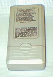
Attention: Do not use this transmitter if the 9 volt battery inside is over 3 months old. Refer to CaddieCommand Owners Manual ® for operating instructions prior to use. (For a free copy, write Kangaroo Motorcaddies, 108 Mill Spring Rd., Columbus NC 28722.) Use of this item implies adherence to Agreement of Sale for safe and prudent use with Hillcrest motorcaddies, on golf courses only. FCC ID: OVPTX600-845C KANGAROO PRODUCTS CO. COLUMBUS, NC 28722 MADE IN USA THIS DEVICE COMPLIES WITH PART 15 OF FCC RULES. OPERATION OF THIS DEVICE IS SUBJECT TO THE FOLLOWING TWO CONDITIONS: (1) THIS DEVICE MAY NOT CAUSE HARMFUL INTERFERENCE, AND (2) THIS DEVICE MUST ACCEPT ANY INTERFERENCE RECEIVED, INCLUDING INTERFERENCE THAT MAY CAUSE UNDESIRED OPERATION. MODEL NO. TX600-845C
Operational Description
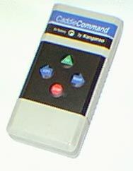
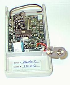
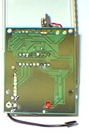
Description of Kangaroo Products Company Transmitter Model TX600-845C FCC ID OVPTX600-845C Form 731 Confirmation Number EA96737 The transmitter is a handheld device used to control a motorized golf caddie, used exclusively on golf courses. A companion receiver is mounted on the caddie and receives four commands from the transmitter: stop, go, turn left, and turn right. Please refer to the schematic and block diagram of the transmitter. The transmitter is controlled by a Microchip PIC series microprocessor running on a 3.58MHz ceramic resonator, U3 on the schematic. Radio transmission is accomplished through the use of a Linx Technoligies module, model number TXM-900-HP-II, U1 on the schematic. This module tunes eight channels, binary selectable using three digital logic inputs: 903.37MHz 906.37MHz 907.87MHz 909.37MHz 912.37MHz 915.37MHz 919.87MHz 921.37MHz The transmitter module uses direct FM modulation with an occupied bandwidth of 32KHz. The microprocessor controls two of the three channel selection lines directly, with the third being set using a solder jumper on the circuit board. The microprocessor also controls the powerdown status of the transmitter module and sends data serially to the module for modulation and transmission. The antenna used by the transmitter is a 1/4 wave length of #18 gauge copper wire, and is not user accessible. It is soldered to the circuit board. A 9V battery is connected to J5. The transmitter is normally not powered until the user presses a key on the four button keypad, connected to J2. Then, P-channel FET Q1 turns on and supplies power to the transmitter circuitry while a key is pressed and for up to three seconds thereafter. This delay is provided by R17 and C9. U6 is a voltage regulator providing five volts to the rest of the circuitry. Comparator U5 provides low battery indication and power on reset functions for the microprocessor. This prevents transmissions when the battery voltage falls below 6 volts. The LED D3 is flashed to indicate to the user that a key has been pressed or released, and whether the battery voltage is low. The function of the LED is under software control. Device U4 is a serial EEPROM memory used to store device configuration parameters such as the radio channel and communications code. Connector J4 is used for production test and configuration and is not connected in normal operation. The transmitter transmits a data burst consisting of 32 bits, each bit being 366 microseconds in duration. The bits are modulated using a 1/3-2/3 duty cycle technique. Thus, the minimum pulse width is 122 microseconds, and the maximum is 244 microseconds. As long as the user holds a key active, the transmitter sends data bursts at approximately 164ms intervals, with a pseudorandom variation of +/-64 milliseconds. When the user releases the key, the transmissions stop. The block diagram contains notations on several signals which have clock or repetitive signals. The highest frequency used (apart from the Linx Technoligies module) is 3.58MHz, the resonator on the microprocessor. The next highest clock frequency is approximately 50KHz, used sporadically on the serial bus connected to the serial EEPROM memory. The next highest frequency signal is the communicated data stream, at about 2800 bits per second. The Linx Technoligies module uses a 12MHz reference crystal oscillator and a 902-928MHz VCO as part of its frequency synthesizer.
Schematics
Date: February 4, 2000 Sheet 1 of 1Size Document Number REV B 100028 B Title CADDIE COMMAND TRANSMITTER (C) 1999FINCASTLE, VA 24090562 OAK HILL ROADATLANTIC QUALITY DESIGN, INC. 9V 12 J5CON2 C8100NF R17330K D4MA152WA C94.7UF/10V V9 Q1NDS352P C104.7UF/10V C11 100NF VS IN 1 OUT 3 GND 2 U6LM3480IM3-5.0 C13100NF VCC VDD C123.3UF/6.3V TEST/PROG 12345 J4CON5 VCC VCC R8100K VCC A0 1 A1 2 A2 3 GND 4 VCC 8 TEST 7 SCL 6 SDA 5 U424C01 VCC 12 3 J3 JMP3 R1010KR910K RA0 17 RA1 18 RA2 1 RA3 2 RTCC 3 MCLR 4 OSC1 16 OSC2 15 RB0 6 RB1 7 RB2 8 RB3 9 RB4 10 RB5 11 RB6 12 RB7 13 U3PIC16C54C-XT/P VSS 3 2 U2A4049 R18470 D1MA152WA D2MA152WA KEYPAD STOPLEFTGORIGHT 12345 J2CON5 R5 100K R3100K R1100K R2100K 5 4 U2B4049 7 6 U2C4049 9 10 U2D4049 Y1 3.58MHZ R613K R710K AGND 1 DGND 9 VCC 8 ANT 2 CS0 3 CS1 4 CS2 5 CTS 6 PDN 7 DAT 10 U1TXM900 1 J1ANTENNAC2100NF VCC C13.3UF/6.3V VCC TX/LOWBAT R16330 D3RED LED 11 12 U2E4049 14 15 U2F4049 R11100K R4100K R1910K VCC VS C3100PF C5100PF R2010K VCC R1210K 3 2 1 84 U5A LM393 R2110K R22100K V9 VS R1582KR1410K D5 MA152WA VS R13100K VS 5 6 7 84 U5B LM393 GND VCC--- --- DEVICE ------------ 8 1 CD4049 C6100NF C4100NF C7100NF VCC VCC VCC 5 14 PIC16C54 FILE 1077.SCH
Test Report
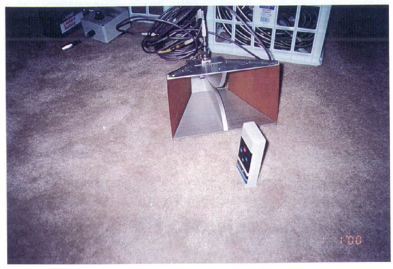
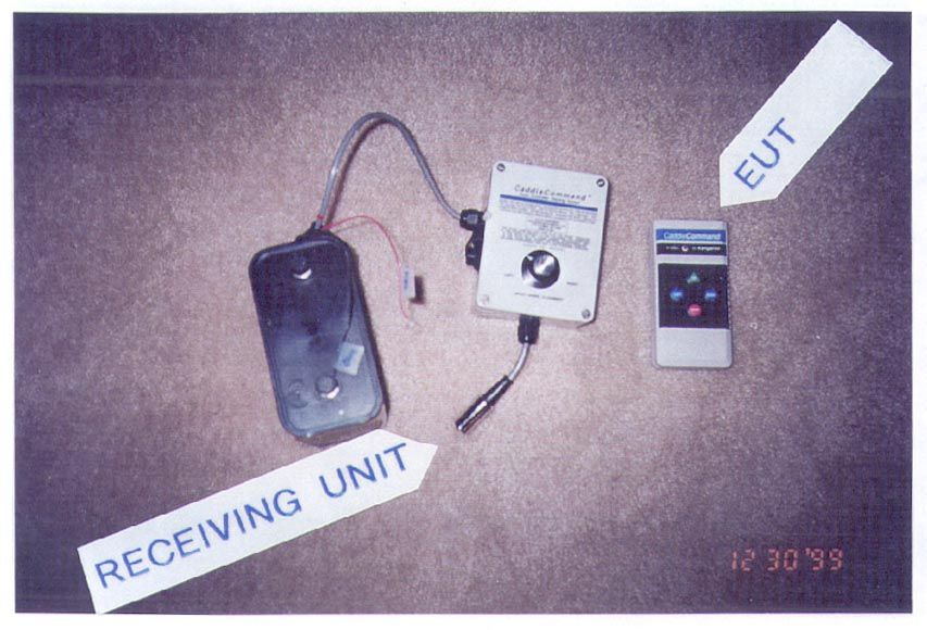
1 ™ TEMPEST INC. 112 Elden Street Herndon, Virginia 20170 (703) “TEMPEST” (836-7378) FAX: 709-9565 e-mail: [email protected] http://www.tempest-inc.com *** Our 15th Year in Business: 1985 - 2000 *** Report of Electromagnetic Interference Testing Performed in Accordance with the Rules of the Federal Communications Commission (Title 47, Para. 15.249 of the United States Code) on the “Caddie Command” Remote Control Unit Model TX600-845C made by Kangaroo Products Company P.O. Box 607, Columbus North Carolina 28722 by_______________________ Louis T. Gnecco, M.S.E.E., President Certified Electromagnetic Compatibility Engineer: Cert.# EMC-000544-NE Certified TEMPEST Professional, Level II January 3, 2000 COPYRIGHT 1999 BY TEMPEST INC.: This document may not be reproduced, recorded electronically, or transmitted electronically, in whole or in part, without the written consent of TEMPEST INC. 2 Abstract As requested by Kangaroo products, Inc. During the Period of December 28, 1999 - January 3, 2000 TEMPEST INC. performed Electromagnetic Compatibility tests in accordance with Title 47, Para. 15.285 Of The United States Code, on the Model TX600-845C “Caddie Command” made by Kangaroo Products, Inc. of Columbus, North Carolina, hearin called the Equipment Under Test (EUT.) The Equipment Under Test produces signals at approximately 910 MHz with a maximum field strength of 35.5 millivolts per meter (peak) measured at a distance of 3 meters. This is in compliance with Title 47, Para. 15.249 of the United States Code which requires the signal to have an average value of 50 millivolts per meter or less. These signals have a duty cycle of approximately 6% whenever a button is pushed. Because of the application, it is estimated that this will occur less than 1% of the time that the device is in use, for an overall duty cycle of 0.06% or less. The emissions produced by the Equipment Under Test comply with the requirements of Title 47, Para. 15.249 of the United States Code. We recommend that production units maintain the same configuration as the sample tested. 3 Table of Contents SectionTitlePage Cover page1 Abstract 2 Table of Contents3 List Of Illustrations4 List of Tables4 Reference Documents4 1.0 Introduction.5 1.1 Purpose.5 1.2 Test Location.5 1.3 Cognizant Personnel.5 2.0Description of the Equipment Under Test.6 3.0Test Procedures.6 3.1Test Equipment.6 3.2Calibration Check6 3.3 Dynamic Range and Detection System Sensitivity Tests.6 3.4 Frequency Stability Test.7 3.5 Local Interference Test:7 3.6Case Leakage Test.7 3.7Spurious Response Test.7 3.8Operational Test.7 3.9Cursory Tests.8 3.10Measurements.8 4.0 Results.8 5.0Conclusions and Recommendations.8 Appendix A: Illustrations9 Appendix B: Tables12 Appendix C: Glossary15 About TEMPEST INC.16 4 List of Illustrations FigureTitlePage 1Equipment Under Test 10 2Equipment Under Test 11 List of Tables Table TitlePage 1List of Test Equipment Used13 2Test Data 14 Reference Documents: TITLE 47, PARA. 15.285 OF THE UNITED STATES CODE 5 1.0Introduction. As requested by Kangaroo Products, Inc. During the Period of December 28, 1999 - January 3, 2000 TEMPEST INC. performed Electromagnetic Compatibility tests in accordance with Title 47, Para. 15.285 Of The United States Code, on the Model TX600-845C “Caddie Command” hereafter called the Equipment Under Test, made by Kangaroo Products, Inc. of P.O. Box 607, Columbus, North Carolina. 1.1 Purpose. The purpose of this test was to determine if the Equipment Under Test complies with the requirements of Title 47, Para. 15.285 of The United States Code, otherwise known as the Rules of the Federal Communications Commission. 1.2 Test Location. All testing was performed in the Open Area Test Site or in the laboratory facilities of TEMPEST INC. 112 Elden St. Herndon,. Virginia 20170 1.3 Cognizant Personnel. The following personnel conducted, witnessed, or are cognizant of the test: Mr. Hank Wallace, President Atlantic Quality Designs, Inc. 562 Oak Hill Rd., Fincastle, Virginia 24090 ( 540) 966-4356 fax: 4358 Mr. Louis T. Gnecco, President, TEMPEST INC. 112 Elden St. Herndon, Virginia 20170-4809 (703)-836-7378 e-mail: [email protected] 6 2.0Description of the Equipment Under Test. The Equipment Under Test is a hand held remote control unit operating in the 902 - 928 MHz frequency band. It is used to send commands to a remotely controlled golf caddie, which carries a set of golf clubs. As shown in figure 1, the Equipment Under Test is 2 3/8 inches wide, 1 inch high, and 4 3/4 inches long and is powered by a 9 volt battery. When a button is pushed, it transmits commands in 15 millisecond bursts, randomly spaced in increments of 250 milliseconds apart, with an overall duty cycle of approximately 6% whenever a button is pushed. Because of the application, it is estimated that this will occur less than 1% of the time that the device is in use, for an overall duty cycle of 0.06% or less. Figures 1 and 2 depict the Equipment Under Test . 3.0Test Procedures. As described below, all testing was performed in accordance with Title 47, Para. 15.285 Of The United States Code, using TEMPEST INC.’s FCC- listed Open Area Test Site (OATS.) 3.1Test Equipment. Table 1 is a list of the test equipment used. As shown in the table, a Double Ridged Waveguide Horn antenna and a Hewlett-Packard spectrum analyzer were used to detect the emissions produced by the Equipment Under Test. 3.2Calibration Check. Using its internal calibration source, the calibration of the spectrum analyzer was verified both immediately before and immediately after the test. 3.3 Dynamic Range and Detection System Sensitivity Tests. Before testing, the dynamic range of the instrumentation was determined to be 80 dB, and the detection system sensitivity was -80 dBm. 7 3.4 Frequency Stability Test. The Equipment Under Test and the receive antenna were moved to verify that the signal did not drift off the display. No such drift was found. 3.5 Local Interference Test. At each t…
Text truncated - open the document above for the full version.
Contact Information
Applicant
Michael McCue(President)
Test Firm
Tempest Inc.Louis Gnecco
Technical Specifications
| # | Rule Parts | Frequency Range | Power Output |
|---|---|---|---|
| 1 | 15C | 903.37 MHz - 921.37 MHz | - |
Other Applications from Kangaroo Products Company

OVPRX600-840C
Mar 06, 2000Kangaroo CaddieCommand Radio Receiver
Equipment Class
CYY - Communications Receiver used w/Pt 15 Transmitter