OVVGMRS188222 Channels FRS/GMRS
Bonso Electronics Ltd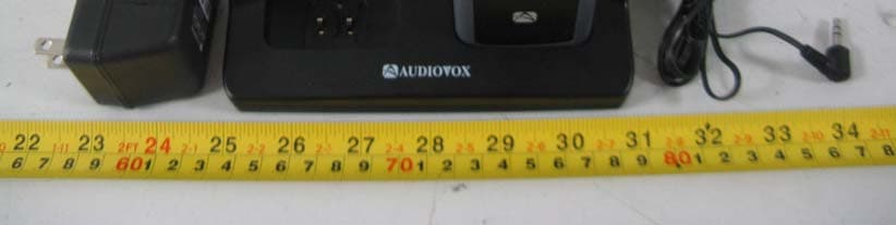
Click to zoom
Application Details
- Equipment Class
- FRF - Part 95 Family Radio Face Held Transmitter
- Date of Grant
- Apr 17, 2008
- Application Purpose
- Original Equipment
- Date of Application
- Apr 17, 2008
- Equipment Note
- 22 Channels FRS/GMRS
- Frequency Range
- 462.55000000 - 462.72500000
- Company
- Bonso Electronics Ltd
- Country
- Hong Kong
Documents & Files
Document Text
Text extracted from the exhibit documents filed with the FCC. Open a document above to read the original.
Users Manual
128-8333 1 of 30 Model: GMRS1882CH Customer Service 1-800-290-6650 Released:Jan-28-08 Owner's Manual General Mobile Radio Service (GMRS) 128-8333 2 of 30 2 THIS DEVICE COMPLIES WITH PART 15 OF THE FCC RULES. OPERATION IS SUBJECT TO THE FOLLOWING TWO CONDITIONS: (1) THIS DEVICE DOES NOT CAUSE HARMFUL INTERFERENCE, AND (2) THIS DEVICE MUST ACCEPT ANY INTERFERENCE RECEIVED, INCLUDING INTERFERENCE THAT MAY CAUSE UNDESIRED OPERATION. 128-8333 3 of 30 CAUTION SAFETY INFORMATION Your wireless hand-held portable transceiver contains a low power transmitter. When the PTT button is pushed (or the VOX mode is enabled) it sends out radio frequency (RF) signals. The device is authorized to operate at a duty factor not to exceed 50%. In August 1996, the Federal Communications Commissions (FCC) adopted RF exposure guidelines with safety levels for hand-held wireless devices. Important:To maintain compliance with the FCC' s RF exposure guidelines hold the transmitter at least 1 inch (2.5 centimeters) from your face and speak in a normal voice, with the antenna pointed up and away. If you wear the handset on your body while using the headset accessory, use only the Audiovox supplied carry clip for this product and ensure that the antenna is at least 1 inch (2.5 centimeters) from your body when transmitting. Use only the supplied antenna. Do not use your transceiver with a damaged antenna. Unauthorized antennas, modifications, or attachments could damage the transmitter and may violate FCC regulations. Performance: Your transceiver will only achieve its maximum operating range when communicating with other transceivers across open and flat areas or between elevated points. Normally occurring environmental factors such as buildings, trees, terrain and weather, or interference from other radio or electrical equipment, may have adverse effects on the transceiver's effective range. These are not indicative of a fault condition. Avoid placing the GMRS1882CH radio transceiver for prolonged periods of time in direct sunlight or temperatures below -4°F (-20°C) or above 140 °F (60°C). Place the rubber cover on jacks when not in use. 3 128-8333 4 of 30 WARNINGS: Battery Care Never attempt to charge alkaline or dry cell batteries, as batteries may burst causing personal injury and damage to the product. If rechargeable batteries are used, such as Nickel Metal Hydride (Ni-MH), use only the supplied Audiovox-approved rechargeable batteries. Use of the Audiovox charger (also supplied) with other brands of batteries is not recommended, as battery charging times will vary with different brands. Refer to the Manufacturer’s instructions for charging other brands of batteries. Battery Disposal In general, if handled improperly, batteries pose a risk of fire or burns. Do not disassemble, crush, puncture, short external contacts, or dispose of the batteries in fire or water. Dispose of the batteries in a environmentally safe manner and recycle whenever possible. FCC WARNING Replacement or substitution of transistors, diodes or other parts of a unique nature, with parts other than those recommended by the manufacturer, may cause a violation of the technical regulations of Part 15 of FCC Rules. GMRS LICENSE: USE OF THIS RADIO WITHIN THE UNITED STATES REQUIRES AN FCC GMRS LICENSE. AN INDIVIDUAL 18 YEARS OF AGE OR OLDER, WHO IS NOT A REPRESENTATAIVE OF A FOREIGN GOVERNMENT, IS ELIGIBLE TO APPLY FOR A GMRS SYSTEM LICENSE. YOU WILL NEED TWO FORMS FROM THE FCC: FCC FORM 159, AND FCC FORM 605 (MAIN FORM AND SCHEDULE F). YOU CAN FIND THE FORMS ONLINE AT: HTTP://WWW.FCC.GOV/FORMPAGE.HTML, OR CALL 1-800-418-3676. 4 128-8333 5 of 30 5 1.Battery Door 2.Monitor/Backlight Button 3.Detachable Carry Clip 4.Push-To-Talk (PTT) Button 5.Antenna 6.External Speaker(SPK)/Micro- phone (MIC)/Charge (CHG) Jack 7.Built-in Speaker 8.Liquid Crystal Display (LCD) Model GMRS1882CH (FCC License Required) 9.Built-in Microphone 10.Up Channel/Volume Button 11.Down Channel/Volume Button 12.MODE/Weather Button 13.Power On/Off & Scan Button 14.VOX Button 15.White Flashlight LED 16.Flashlight Enable Button 17.Battery Charging Contacts 1 2 3 4 5 8 11 9 12 6 14 10 13 7 3 (REF) 1 (REF) 17 16 15 18.Crank Charging Lever 18 128-8333 6 of 30 6 Model GMRS1882CH DISPLAY 1.Beep Tone Indicator: Icon appears when beep button confirmation tone is selected; icon disappears when tone is off. 2.Key Lock Indicator: Icon appears when the keypad is locked. This function disables keys such as channel up/down, SCAN and MODE. 3.Monitor Indicator: Icon appears when the Monitor (M) button is pressed and the channel monitor function is activated. 4.Signal Strength Indicator: Icon appears when a signal is being transmitted. The icon consists of five bars to indicate transmit signal power level. 5.HI/LO Indicators: Power level indicator appears when the transmit power is set to desired output power on the GMRS channels. 6.Large Segment Display: Indicates the channel number in use in GMRS/FRS mode or WEATHER BAND mode. 7.Scan Indicator: This function allows the user to scan a channel (and tone code, if present) every .5 second to search for a valid signal. 8.RogerBeep Tone On/Off Indicator: This icon appears when the Roger Beep tone is on, and disappears when tone is not in use. 9.Battery Level Indicator: Icon indicates the battery charge level. 10.Signal Receive Indicator: RX icon appears when a signal is being received. 1 2 3 4 5 6 7 8 9 10 12 13 14 11.Small Segment Display: Displays the CTCSS tone option for each main channel from 01-38. 11 128-8333 7 of 30 7 13.Dual Watch Mode Indicator: Indicator appears when dual watch mode is active. 14.Voice Activated Transmission (VOX) Indicator: This function allows hands free conversation. The indicator appears when the VOX mode is activated. Equipment and Accessories Supplied 1.Radio (2)GMRS1882CH 2.Owner’s Manual128-8333 3.Desktop ChargerGMRS18DS 4.AC Wall AdapterGMRS25AC 5.Rechargeable (NiMH) Batteries (8)GMRS6BAT 6.Detachable Carry ClipGMRS122…
Text truncated - open the document above for the full version.
Block Diagram
GMRS1882 - Block Diagram.sch-1 - Fri Feb 29 15:57:38 2008
Cover Letter(s)
Page 1 of 1 Bay Area Compliance Laboratories Corp. 1274 Anvilwood Avenue Sunnyvale, CA 94089 USA Phone: (408)-732-9162 Fax: (408)-732-9164 www.baclcorp.com 2008-05-06 Federal Communications Commission Office of Engineering and Technology 7435 Oakland Mills Rd. Columbia, MD 21046 Phone: 301-362-3000 Fax: 301-362-3290 Subject: FCC Correspondence Response To Whom it May Concern: BACL has made the requested revision based on the correspondence below. Following is the original FCC Correspondence with responses featured in red. The necessary clarifications, revisions, and upload of requested documentation has been completed. If there are any other concerns or questions regarding this submission please contact us at [email protected] . Thank you. Douglas Méndez Document Control Supervisor Bay Area Compliance Laboratories Corp. Phone: (408)732-9162 Fax: (408)732-9164 From: Tim Harrington [email protected] Re: FCC ID: OVVGMRS1882 Applicant: Bonso Electronics Ltd Correspondence Reference Number: 51954 Date of Original E-mail: 05/06/2008 FCC Correspondence: Please correct one grant line-entry to use K0 not KO Response: The grant line-entry item for the emission designator has bee revised to K0
External Photos
EXHIBIT B - EUT EXTERNAL PHOTOGRAPHS EUT-Full View EUT-Top View EUT-Bottom View EUT-Left Side View EUT-Right Side View
ID Label/Location Info
Document Number Bonso Group Rev # Title : GMRS1882 General Information Application : Release Date : 19 Feb. 2008 Page 1 of 1 LABEL FORMAT & LOCATION CHECK LIST (FCC) Testing required for FCC and SAR. 1. FRN : 0012797494 2. FCC ID : OVVGMRS1882 3. Model Number : GMRS1882 4. Trade Name : BONSO 5. Model Description : 22Channels FRS/GMRS 6. Applicant Company Name : BONSO ELECTRONICS LTD. Address : Unit 1106-1110, 11/F., Star House, 3 Salisbury Road, Tsimshatsui, Kowloon, HongKong. Mr. Harry J Lee / Director R&D & Engineering Telephone : +852 2605 5822, +86 755 2731 1888 Ext 228 Fax. : +852 2691 1724, +86 755 2731 1999 E-mail : [email protected] 7. Manufacturer Company Name : BONSO ELECTRONICS (SHENZHEN) CO., LTD. Address : 59 Da Yang Road, Da Yang Synthetical Develop District, Fu Yong, ShenZhen, China Postcode : 518103
Internal Photos
EXHIBIT C - EUT INTERNAL PHOTOGRAPHS EUT-Battery Uncovered View EUT-Uncovered View EUT-Main Board Top View EUT-Main Board Bottom View EUT- Main Board Unshielded Top View EUT-Hand Charger Part View EUT-Speaker View
Operational Description
Model No: GMR1882 Drawing No: GMRS1882-TECH Customer: AUDIOVOX Title: GMRS1882 TECHNICAL DESCRIPTION Rev. Date: Feb. 29 , 2008 Created by: Approved by: Rev. No: 00 For Stage : Release Date : Feb. 29, 2008 Page 1 of 4 These drawings and specifications are the property of BONSO Electronics Ltd. and shall not be reproduced or copied, or used as reference for design, manufacture, and sale of device without permission. BONSO ELECTRONICS LTD. GMRS1882 CIRCUIT DESCRIPTION Model No: GMR1882 Drawing No: GMRS1882-TECH Customer: AUDIOVOX Title: GMRS1882 CIRCUIT DESCRIPTION Rev. Date: Feb. 29 , 2008 Created by: Approved by: Rev. No: 00 For Stage : Release Date : Feb. 29, 2008 Page 2 of 4 These drawings and specifications are the property of BONSO Electronics Ltd. and shall not be reproduced or copied, or used as reference for design, manufacture, and sale of device without permission. BONSO ELECTRONICS LTD. 1. GENERAL DESCRIPTION The GMRS1882 FRS/GMRS radio is a self-contained transceiver unit with integral antenna intended for use as a general communication tool. It is designed to operate on all 22 channels allocated by the FCC. The useable range, while dependent upon terrain and other radio propagation principles, is typically ten miles. The GMRS1882 uses the maximum transmit power allowed to help ensure the maximum communication range. Features include: 22GMRS Channels, Page and LCD Display. The unit is equipped with an external Headset option connector. Five AAA alkaline batteries that are readily available in retail outlets supply operating power. An automatic power savings feature allows the typical standby battery life to extend to more than 4days. 2. FREQUENCY DETERMINING CIRCUITS The fundamental frequency for both the transmitter and the receiver local oscillators are controlled by a Phase Lock Loop (PLL) circuit in IC501 (AN29160). The frequency of operation of the FRS/GMRS Voltage Controlled Oscillator (VCO), composed of Q303 and Q304 operating is phase locked to a Voltage Controlled Crystal Reference (VCXO) operating at 20.95MHz (X501). The VCO is locked to the fundamental of the transmit signal in the transmit mode and is locked to the receive 1 st LO (Fundamental channel frequency minus 21.4MHz) in the receive mode. The crystal reference frequency is shared with the 2 nd LO of 20.95MHz. 3. TRANSMITTER CIRCUITS The transmitter amplifies the 0dBm signal from the VCO to approximately 35dBm that is fed to the antenna. The transmitter is a three stage amplifier composed of Q201, Q203,Q204 and Q206. The first two stages are operated class A and the final is operated class B in full saturation to help prevent unwanted amplitude modulation. The fundamental transmit signal is fed through an elliptical Low Pass Filter (5-pole, 2 zero) in order to suppress the harmonics to below –50dBc. The desired frequency modulation of the carrier is accomplished by modulating the current in the VCO directly with the microphone audio signal. The microphone Model No: GMR1882 Drawing No: GMRS1882-TECH Customer: AUDIOVOX Title: GMRS1882 CIRCUIT DESCRIPTION Rev. Date: Feb. 29 , 2008 Created by: Approved by: Rev. No: 00 For Stage : Release Date : Feb. 29, 2008 Page 3 of 4 These drawings and specifications are the property of BONSO Electronics Ltd. and shall not be reproduced or copied, or used as reference for design, manufacture, and sale of device without permission. BONSO ELECTRONICS LTD. audio is conditioned with a limiter circuit (Pin 47) in IC501 (AN29160) to limit maximum deviation to +/-2.5KHz and a splatter filter (Pin 50 and 51) at 2.8KHz. The limiter circuit and splatter filter insures that the occupied bandwidth of the FM modulated signal meets FCC requirements under all input conditions. 4. RECEIVER CIRCUITS The received signal from the antenna is band limited to 600MHz by the transmitter harmonic filter. The desired signal is fed to low noise amplifier (LNA-Q102) centered from 460 to 470MHz that provides approximately 10 dB of gain. The output of the LNA is filtered with a Band Pass Filter (SF101) with pass band of 460 to 470MHz and stop-band attenuation of 40dB. The filtered receive signal is one input to the 1 st mixer (Q104), the other mixer input (1 st LO) is the output of the VCO at the desired channel frequency minus 21.4MHz. The output of the mixer is turned to the 1 st IF of 21.4MHz. The 1 st IF is transformer coupled for impedance matching to a crystal filter (CF101) centered at 21.4MHz with a bandwidth of +/-3.75KHz. The filtered 1 st IF is fed to the 2 nd mixer input of the One Chip IC (Pin 21 of IC501). The 2 nd LO (20.95MHz) is generated by VCXO that is the reference frequency for the PLL in IC501 (AN29160). The 2 nd mixer output of 450KHz is filtered through a 4 section ceramic filter that in combination with the 21.4MHz crystal filter provides approximately 50dB of adjacent channel attenuation. The 450KHz 2 nd IF is then amplified, limited and fed to a quadrature detector for FM demodulation. The resulting audio output signal is amplified to provide 150mW of Speaker Amp (Pin 53, 54, 56 of IC501). A squelch circuit is provided (Pin 30 and 32 of IC501) to mute the receiver noise under low RF signal conditions. The squelch circuit amplifies and detects noise in a narrow bandwidth at approximately 5KHz. When the detected noise exceeds a threshold set to trigger at approximately 9dB SINAD receive signal strength, the audio output is muted. 5. TRANSMIT/RECEIVE SWITCH CIRCUITS When the radio is in the transmit mode, pin diode switches D101 and D201 are both turned on (representing less than 0.7ohms). D201 allows the transmit signal to pass to the antenna and D101 shorts one leg of a T matching network (L101 and C104) to ground in the Model No: GMR1882 Drawing No: GMRS1882-TECH Customer: AUDIOVOX Title: GMRS1882 CIRCUIT DESCRIPTION Rev. Date: Feb. 29 , 2008 Created by: Approved by: Rev. No: 00 For Stage : Release Date : Feb. 29, 2008 Page 4 of 4 These drawings and specifications are the propert…
Text truncated - open the document above for the full version.
Parts List/Tune Up Info
Model No :GMRS1882 Drawing No: GMRS1882-TAP. Customer : AUDIOVOX Title: GMRS1882 Test & Alignment Procedure Rev. Date: Feb. 29, 2008 Created by: Approved by: Rev. No: 00 For Stage : Release Date : Feb. 29, 2008 Page 1 of 8 BONSO ELECTRONICS LTD. These drawings and specifications are the property of BONSO Electronics Ltd. and shall not be reproduced or copied, or used as reference for design, manufacture, and sale of device without permission. GMRS1882 Test and Alignment Procedure Model No :GMRS1882 Drawing No: GMRS1882-TAP. Customer : AUDIOVOX Title: GMRS1882 Test & Alignment Procedure Rev. Date: Feb. 29, 2008 Created by: Approved by: Rev. No: 00 For Stage : Release Date : Feb. 29, 2008 Page 2 of 8 BONSO ELECTRONICS LTD. These drawings and specifications are the property of BONSO Electronics Ltd. and shall not be reproduced or copied, or used as reference for design, manufacture, and sale of device without permission. REVISION SHEET Rev. Code Rev. Date Revision Revised By: M-00 Feb.29,2008 Model No :GMRS1882 Drawing No: GMRS1882-TAP. Customer : AUDIOVOX Title: GMRS1882 Test & Alignment Procedure Rev. Date: Feb. 29, 2008 Created by: Approved by: Rev. No: 00 For Stage : Release Date : Feb. 29, 2008 Page 3 of 8 BONSO ELECTRONICS LTD. These drawings and specifications are the property of BONSO Electronics Ltd. and shall not be reproduced or copied, or used as reference for design, manufacture, and sale of device without permission. TABLE OF CONTENT 1. RECOMMENDED EQUIPMENT ....................................................................................... 4 2. TEST PREPARATION ................................................................................................... 4 3. VOLTAGE REGULATOR TEST ....................................................................................... 4 4. VCO ADJUSTMENT ......................................................................................................... 4 5. TRANSMITTER FREQUENCY ALIGNMENT ................................................................. 5 6. TRANSMITTER OUTPUT POWER CHECK ................................................................... 5 7. TRANSMITTER DEVIATION ADJUSTMENT ............................................................... 5 8. RECEIVER ALIGNMENT ................................................................................................. 6 9. SQUELCH THRESHOLD AND HYSTERISIS ............................................................... 6 10. VOX TEST ...................................................................................................................... 6 11. LOW BATTERY LEVEL TEST ................................................................................... 6 12. JACK CHARGING TEST .............................................................................................. 6 13. DESKTOP CHARGING TEST ...................................................................................... 7 14. FREQUENCIES & CODE TABLE ............................................................................... 7 14.1 FRS & GMRS .................................................................................................... 7 14.2 WX BAND .......................................................................................................... 8 14.3 CTCSS CODE ....................................................................................................... 8 Model No :GMRS1882 Drawing No: GMRS1882-TAP. Customer : AUDIOVOX Title: GMRS1882 Test & Alignment Procedure Rev. Date: Feb. 29, 2008 Created by: Approved by: Rev. No: 00 For Stage : Release Date : Feb. 29, 2008 Page 4 of 8 BONSO ELECTRONICS LTD. These drawings and specifications are the property of BONSO Electronics Ltd. and shall not be reproduced or copied, or used as reference for design, manufacture, and sale of device without permission. 1. RECOMMENDED TEST EQUIPMENT 1.1 HP8920A,B Radio Communication Tester or equivalent with Spectrum Analyzer option. 1.2 Fluke 187 Digital Voltmeter or equivalent 1.3 HPE3615A Power Supply or equivalent 2. TEST PREPARATION 2.1 Connect a 6.0Vdc power supply to the positive battery terminal input point and the negative battery terminal input point (GND) into the negative terminal. 2.3 Connect the HP8920A,B RF Output port to the ANT point. 2.4 SPK (+) should be connected to the Audio In Hi and SPK (-) should be connected to the Audio In Lo of the HP8920B. 2.5 Set the unit at CH1 (462.5625MHz) 3. VOLTAGE REGULATOR TEST 3.1 MCU Regulator - Connect a voltmeter to Pin6 of IC501 (MCU REG) and measure the voltage. The value must be between TBD. 3.2 RX Regulator - Connect a voltmeter to Pin7 of IC501 (RX REG) and measure the voltage. The value must be between TBD. 3.3 TX Regulator - Connect a voltmeter to Pin8 of IC501 (TX REG) and measure the voltage. The value must be between TBD. 3.4 VCO Regulator - Connect a voltmeter to Pin10 of IC501 (VCO REG) and measure the voltage. The value must be between TBD. 3.5 IC Regulator - Connect a voltmeter to Pin11 of IC501 (IC REG) and measure the voltage. The value must be between TBD. 4. VCO ADJUSTMENT 4.1 Set the unit at CH1 and connect a digital voltmeter to VCO TP (R502 & C522 connect point). 4.2 Press and hold the PTT Button so the unit is in transmit mode. 4.3 Adjust L306 until the voltmeter reads 1.2 to 1.3Vdc (without VCO Plate). L306 is located under the shieldcan. Solder VCO Plate and let temperature stabilize. Recheck TX VCO at CH1, should be 1.0~1.3 Vdc 4.4 Release the PTT button so the unit will be in receive mode. 4.5 Observe the voltage at VCO TP, the voltage should be 0.6~2.5Vdc. 4.6 Set the unit at CH14. 4.7 Press and hold the PTT button so the unit is in transmit mode. 4.8 Observe the voltage at VCO TP, the voltage should be 1.0~2.5Vdc. Model No :GMRS1882 Drawing No: GMRS1882-TAP. Customer : AUDIOVOX Title: GMRS1882 Test & Alignment Procedure Rev. Date: Feb. 29, 2008 Created by: Approved by: Rev. No: 00 For Stage : Release Date : Feb.…
Text truncated - open the document above for the full version.
RF Exposure Info
Note: This test report is for the customer shown above and their specific product only. It may not be duplicated or used in part without prior written consent from Bay Area Compliance Laboratories Corp. This report must not be used by the customer to claim product certification, approval, or endorsement by NVLAP or any agency of the U.S. Government. SAR EVALUATION REPORT For Bonso Electronics Co., Ltd. Unit 1106-1110, 11/F Star House 3 Salisbury Road, Tsim Sha Tsui Kowloon, Hong Kong FCC ID: OVVGMRS1882 This Report Concerns: Original Report Product Name: FRS/GMRS FM Portable Transceiver Test Engineer: Jimmy Nguyen Report No.: R0804083-SAR Report Date: 2008-04-14 Reviewed By: Boni Baniqued Prepared By: Bay Area Compliance Laboratories Corp. (BACL) 1274 Anvilwood Ave. Sunnyvale, CA 94089, USA Tel: (408) 732-9162 Fax: (408) 732 9164 Bonso Electronics Ltd. FCC ID: OVVGMRS1882 Report No.: R0804083-SAR SAR Evaluation Report Page 2 of 48 DECLARATION OF COMPLIANCE SAR EVALUATION Rule Part(s): FCC §2.1093 & IEEE 1528 Test Procedure(s): FCC OET Bulletin 65 Supplement C & IEEE 1528 Exposure Category: Portable transceiver General/Uncontrolled Exposure Device Type: FRS/GMRS FM UHF Portable Transceiver Modulation Type: FM TX Frequency Range: 462.5625-462.7125 MHz (FRS/GMRS) 462.5500-462.7250 MHz (GMRS) 467.5625-467.7125 MHz(FRS) Maximum Power Tested: 1.04 Watt (ERP) Antenna Type(s) Tested: Integrated Antenna Body-Worn Accessories: Earphone and Belt clip Face-Head Accessories: None 0.052 mW/g Body-Worn Max. SAR Level(s) Measured: 0.072 mW/g Face-Hold This wireless device has been shown to be capable of compliance for localized specific absorption rate (SAR) for General Population/Uncontrolled Exposure limits specified in ANSI/IEEE Standards and has been tested in accordance with the measurement procedures specified in FCC OET 65 Supplement C. The results and statements contained in this report pertain only to the device(s) evaluated. Tested By: Jimmy Nguyen Testing Engineer EUT Photo Bonso Electronics Ltd. FCC ID: OVVGMRS1882 Report No.: R0804083-SAR SAR Evaluation Report Page 3 of 48 TABLE OF CONTENTS REFERENCE, STANDARDS, AND GUILDELINES.................................................................................................5 SAR Limits....................................................................................................................................................... 6 EUT DESCRIPTION......................................................................................................................................................7 EUT Photo........................................................................................................................................................ 7 FACILITIES AND ACCREDITATION.......................................................................................................................8 DESCRIPTION OF TEST SYSTEM ............................................................................................................................9 Measurement System Diagram ...................................................................................................................... 11 System Components....................................................................................................................................... 12 TESTING EQUIPMENT .............................................................................................................................................20 Equipments List & Calibration Info............................................................................................................... 20 SAR MEASUREMENT SYSTEM VERIFICATION................................................................................................21 System Accuracy Verification ....................................................................................................................... 21 SAR MEASUREMENT RESULTS.............................................................................................................................22 SAR Worst-Case Test Data............................................................................................................................ 22 APPENDIX A – MEASUREMENT UNCERTAINTY ..............................................................................................23 APPENDIX B – PROBE CALIBRATION CERTIFICATES...................................................................................25 APPENDIX C – DIPOLE CALIBRATION CERTIFICATES.................................................................................34 APPENDIX D - TEST SYSTEM VERIFICATIONS SCANS ..................................................................................40 Liquid Measurement Result ........................................................................................................................... 40 APPENDIX E – EUT SCANS ......................................................................................................................................42 APPENDIX F – CONDUCTED OUTPUT POWER MEASUREMENT.................................................................44 Bonso Electronics Ltd. FCC ID: OVVGMRS1882 Report No.: R0804083-SAR SAR Evaluation Report Page 4 of 48 Provision Applicable ...................................................................................................................................... 44 Test Procedure................................................................................................................................................ 44 Test equipment ............................................................................................................................................... 44 Test Results .................................................................................................................................................... 44 APPENDIX G –TEST SETUP PHOTOS .......…
Text truncated - open the document above for the full version.
Schematics
GMRS1882.sch-1 - Thu Apr 03 17:56:23 2008 CHARGER FOR 1882.sch-1 - Fri Feb 29 13:58:28 2008
Test Report
Note: This test report is for the customer shown above and their specific product only. It may not be duplicated or used in part without prior written consent from Bay Area Compliance Laboratories Corp. (Shenzhen). This report must not be used by the customer to claim product certification, approval, or endorsement by NVLAP, NIST, or any agency of the Federal Government FCC PART 95 EMI MEASUREMENT AND TEST REPORT For Bonso Electronics Ltd. Unit 1106-1110, 11/F Star House 3 Salisbury Road, Tsim Sha Tsui Kowloon, Hong Kong FCC ID: OVVGMRS1882 This Report Concerns: Original Report Equipment Type: 22 channels FRS/GMRS Test Engineer: Phoenix Liu Report No.: RSZ08030701 Test Date: 2008-03-29 to 2008-04-17 Report Date: 2008-04-17 Reviewed By: EMC Manager: Green Xu Prepared By: Bay Area Compliance Laboratories Corp. (Shenzhen) 6/F, the 3rd Phase of WanLi Industrial Building, ShiHua Road, FuTian Free Trade Zone Shenzhen, Guangdong, China Tel: +86-755-33320018 Fax: +86-755-33320008 Bonso Electronics Ltd. FCC ID: OVVGMRS1882 Report No.: RSZ08030701 Page 2 of 32 FCC Part95 Report TABLE OF CONTENTS GENERAL INFORMATION.......................................................................................................................................3 PRODUCT DESCRIPTION FOR EQUIPMENT UNDER TEST (EUT) .....................................................................................3 OBJECTIVE...................................................................................................................................................................3 RELATED SUBMITTAL(S)/GRANT(S).............................................................................................................................3 TEST METHODOLOGY..................................................................................................................................................3 TEST FACILITY.............................................................................................................................................................3 SYSTEM TEST CONFIGURATION ..........................................................................................................................5 DESCRIPTION OF TEST CONFIGURATION......................................................................................................................5 EQUIPMENT MODIFICATIONS.......................................................................................................................................5 CONFIGURATION OF TEST SETUP.................................................................................................................................5 BLOCK DIAGRAM OF TEST SETUP................................................................................................................................5 SUMMARY OF TEST RESULTS ...............................................................................................................................6 §1.1307(b)(1) & §2.1093 RF EXPOSURE....................................................................................................................7 STANDARD APPLICABLE..............................................................................................................................................7 MEASUREMENT RESULT: .............................................................................................................................................7 §2.1…
Text truncated - open the document above for the full version.
Contact Information
Applicant
K. W. Chung(R/D & Engineering Director)
Test Firm
Bay Area Compliance Laboratory Corp. (Shenzhen)John Chan
Technical Specifications
| # | Rule Parts | Frequency Range | Power Output | Emission | Tolerance |
|---|---|---|---|---|---|
| 3 | 95A | 462.55 MHz - 462.725 MHz | 1.03 W | 11K0F3E | 5 ppm |
Other Applications from Bonso Electronics Ltd

OVVGMRS1072N
Jun 12, 2007FRS/GMRS Combination
Equipment Class
FRF - Part 95 Family Radio Face Held Transmitter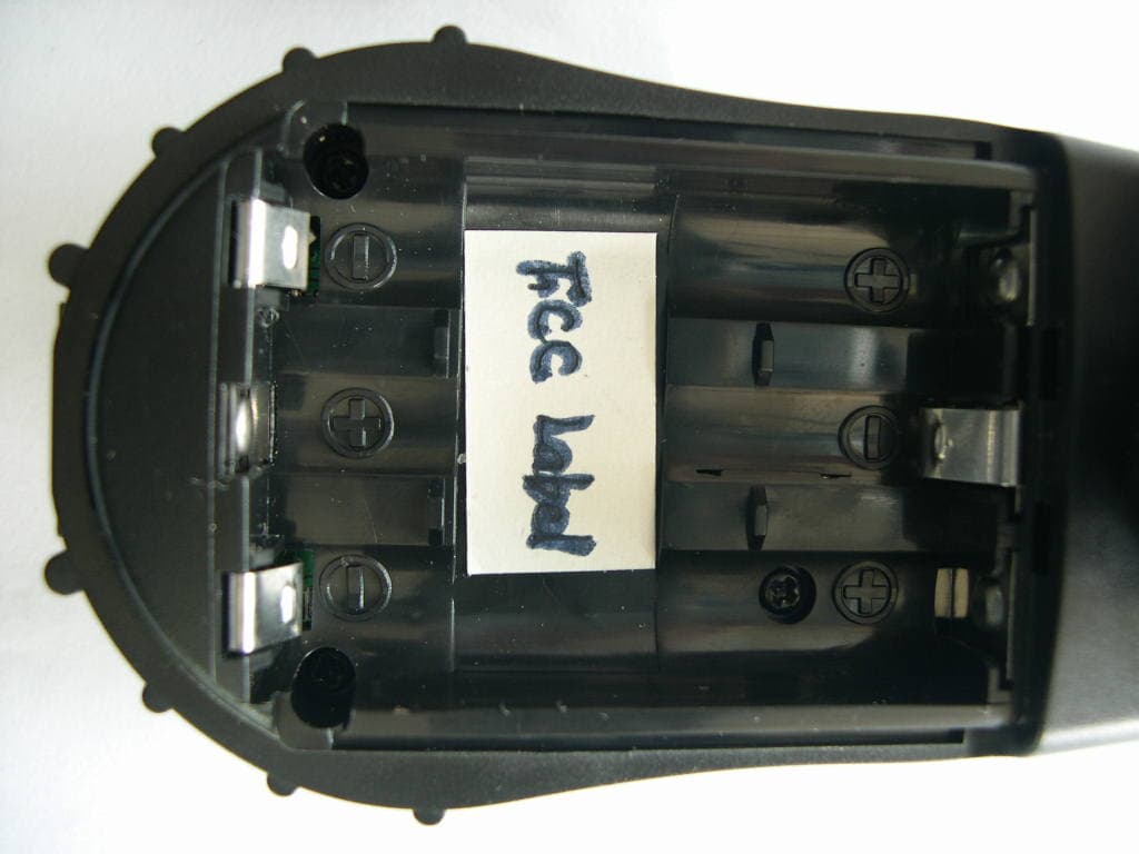
OVVGMRS672
Mar 20, 2007FRS/GMRS COMBINATION
Equipment Class
FRF - Part 95 Family Radio Face Held Transmitter
OVVGMRS2572
Mar 15, 2007FRS/GMRS COMBINATION
Equipment Class
FRF - Part 95 Family Radio Face Held Transmitter
OVVGMRS1072
Mar 05, 2007FRS/ GMRS COMBINATION
Equipment Class
FRF - Part 95 Family Radio Face Held Transmitter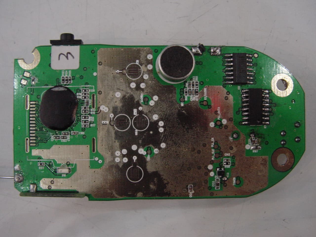
OVVBS004
Jun 14, 2005GMRS/FRS COMBINATION
Equipment Class
FRF - Part 95 Family Radio Face Held Transmitter