OW8LSMC01400Local Status Monitor Controller
ADC Broadband Communications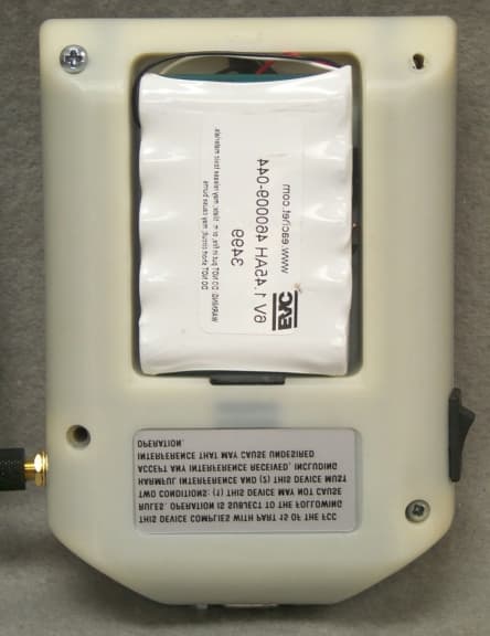
Click to zoom
Application Details
- Equipment Class
- DSS - Part 15 Spread Spectrum Transmitter
- Date of Grant
- Jun 26, 2000
- Application Purpose
- Original Equipment
- Date of Application
- Apr 23, 2000
- Equipment Note
- Local Status Monitor Controller
- Frequency Range
- 2401.50000000 - 2480.00000000
- Company
- ADC Broadband Communications
- Country
- United States
Documents & Files
Document Text
Text extracted from the exhibit documents filed with the FCC. Open a document above to read the original.
Users Manual
® PN XXXXXXXXXX Local Status Monitor LSM controller Installation and Operation Manual CAUTION In order to comply with FCC RF exposure requirements, this device must be installed in such a way as to ensure that a minimum separation distance of 20 cm is always maintained between the antenna and all persons. Note: This equipment has been tested and found to comply with the limits for a Class A digital device, pursuant to Part 15 of the FCC rules. These limits are designed to provide reasonable protection against harmful interference when the equipment is operated in a commercial environment. This equipment generates, uses, and can radiate radio frequency energy and if not installed and used in accordance with the instruction manual, may cause harmful interference to radio communications. Operation of this equipment in a residential area is likely to cause harmful interference in which case the user will be required to correct the interference at his own expense. Local Status Monitor/Controller Installation/Operation Manual PN XXXXXXXXXX \\Adcvs4\vol2\COMMON\00Sawyer\LSM Manual 4-21-00.doc Created on 04/21/00 10:34 AM Page 2 of 6 Section 1 -- Table of Contents SECTION 1 -- TABLE OF CONTENTS_______________________________2 SECTION 2 -- INTRODUCTION_____________________________________3 SECTION 3 – PRODUCT OVERVIEW________________________________4 3a. Wireless SoftLink______________________________________________________________4 3b. Local Status Monitor Controller (LSMC)____________________________________________4 3c. Local Status Monitor (LSM)______________________________________________________4 3d. Craft Software_________________________________________________________________4 SECTION 4 – HARDWARE INSTALLATION__________________________5 a. Network Amplifier_______________________________________________________________5 SECTION 4 – HARDWARE INSTALLATION__________________________9 b. Line Extender__________________________________________________________________9 SECTION 5 – WIRELESS SOFTLINK SOFTWARE INSTALLATION_______13 Step 1_________________________________________________________________________13 Step 2_________________________________________________________________________13 Step 3_________________________________________________________________________13 Step 4_________________________________________________________________________13 SECTION 6 – OPERATION_______________________________________14 a. Introduction___________________________________________________________________14 b. Initializing____________________________________________________________________14 b1 – WSL Setup_________________________________________________________________14 b2 -- LSM Setup____________________________________________________________________ 15 c. Operation_______________________________________________________________________ 16 SECTION 7 -- INDEX_____________________________________________17 Local Status Monitor/Controller Installation/Operation Manual PN XXXXXXXXXX \\Adcvs4\vol2\COMMON\00Sawyer\LSM Manual 4-21-00.doc Created on 04/21/00 10:34 AM Page 3 of 6 Section 2 -- Introduction The purpose of the Local Status Monitor/Controller Installation/Operation Manual is to provide a user-friendly and comprehensive document that makes it easy for technicians to install and operate the LSM/LSMC. The manual includes step-by-step LSM/LSMC installation/operation instructions and accompanying graphics. The information contained in this document is current as of the date of publication and is also compatible with the most recent release of Craft Software as well as the initial release of the LSM/LSMC software. ADC retains the right to change this document, in part or in whole, without prior notice. This document is copyrighted. All rights are reserved. This document may not, in whole or in part be reproduced or transmitted in any form or by any means electronic or mechanical, without the express written consent from ADC. In no event will ADC be liable for any special, incidental, or consequential damages or commercial losses, even if ADC has been advised thereof, as a result of issue of this publication. Local Status Monitor/Controller Installation/Operation Manual PN XXXXXXXXXX \\Adcvs4\vol2\COMMON\00Sawyer\LSM Manual 4-21-00.doc Created on 04/21/00 10:34 AM Page 4 of 6 Section 3 – Product Overview 3a. Wireless SoftLink The Wireless SoftLink, WSL, operates in conjunction with Craft and controls LSMC via an RS232 connection. The WSL software enables technicians to address amplifiers with a local status monitor/local status monitor controller via the Craft software. The WSL can be loaded in any personal computer, or laptop. It must have Craft version 2.0 or higher version software installed to operate properly with the LSM and LSMC. ADC maintains helpdesk technical support to assist with any Craft or Wireless SoftLink software installation or operation issue. You will find complete LSM/LSMC installation/operation instructions in Section 4 of this manual. 3b. Local Status Monitor Controller (LSMC) The Local Status Monitor Controller, LSMC, is a wireless communication module connected to a laptop. The main purpose for the LSMC is to become a two-way wireless link between a ground located laptop and the ADC family of Network Amplifiers or Line Extender. The LSMC will allow Craft software to control the network amplifier through a wireless connection. Technicians can operate the LSMC in a vehicle or attach the LSMC to the belt with a clip attached to the LSMC case. For optimal performance the LSMC should remain relatively stationary during use to prevent any interruption or disconnection of the wireless link with the LSM. 3c. Local Status Monitor (LSM) The Local Status Monitor is an upgrade kit that can be installed in an amplifier. The LSM works in conjunction with the LSM controller as a wireless link to receive commands from a laptop. Once LSM receives command, it will send commands to the ADC family …
Text truncated - open the document above for the full version.
Users Manual
Figure 6-3 Threaded sleeve Section 6 – LSMC Configuration CAUTION In order to comply with FCC RF exposure requirements, this device must be installed in such a way as to ensure that a minimum separation distance of 20 cm is always maintained between the antenna and all persons. Due to RF requirements, ADC recommends operating the LSMC from the vehicle only. 6a. Battery Installation STEP 1 Remove the battery cover from the backside of the LSMC case. See Figure 4-1. STEP 2 Remove the new nickel metal hydride battery from its packaging. STEP 3 Carefully install the new battery pack connector to the controller case connector. See Figure 6-1. The connector is keyed and will fit into the LSMC slot one way only. Make sure connector is firmly in place. STEP 4 Place the battery pack inside the controller case. Carefully fold and lay the connector wires in the battery case beneath the battery during installation of the battery. See Figure 6-2. STEP 5 Replace the battery cover. Slide the cover over the opening until the cover snaps into place. Note: Before using the LSMC for the first time the battery requires a charge of at least three hours. 6b. Antenna Orientation Note: The antenna should already be attached to the LSMC unit when the unit is removed from its packaging. STEP 1 Loosen the threaded sleeve. See Figure 6-3. STEP 2 Figure 6-1 Figure 6-2 Figure 6-4 Local Status Monitor/Controller Installation/Operation Manual PN XXXXXXXXXX ® Charging LED RF SYNC LED Low Batt LED Figure 6-6 Rotate the antenna into a position perpendicular to the LSMC unit. See Figure 6-4. STEP 3 Finger tighten the sleeve and connector nut so the antenna fits snugly to the LSMC unit. 6c. Vehicle DC Adapter Use Introduction the LSMC Vehicle DC Adapter has been designed to charge the unit at the same time the LSMC is active. ADC recommends that the LSMC be operated with the adapter attached unless the need arises to leave the vehicle. The LSMC will operate for approximately five hours of continuous RF SYNC on a full battery charge. STEP 1 Locate the power connector at the top of the case between the RS232 port and the antenna connector. STEP 2 Insert the adapter cord into the power connector slot in the case and plug the power adapter into the vehicle power source. See Figure 4-5. CAUTION: Use of any power adapter other than the one supplied with the LSMC may cause damage to the LSMC unit. Use only the DC adapter shipped with the LSMC. 6d. LED Functions When the battery is charging, the CHARGING LED will light and remain lit. See Figure 4-6. The CHARGING LED will turn off when battery charging is complete. Leave the battery plugged in while the charging light is on. The RF SYNC LED will blink rapidly when the LSMC is polling. When the LSMC connects to an LSM, the RF SYNC LED will appear to be continuously lit with only intermittent blinks. The LOW BATT LED will blink when the battery requires charging. Insert the adapter cord into the power connector slot in the case and plug the power adapter into the vehicle power source. Figure 6-5 Local Status Monitor/Controller Installation/Operation Manual PN XXXXXXXXXX \\Adcvs4\vol2\COMMON\00Sawyer\LSM Stuff to review\Section 6.doc Created on 05/15/00 3:24 PM Page 3 of 3 Note: Leave the DC adapter plugged in for a minimum of three hours to insure complete battery charge. Note: The RF SYNC LED and the LOW BATT LED will blink when LSMC power is on and the unit is idle.
Users Manual
Section 3 – Product Overview 3a. Wireless SoftLink The Wireless SoftLink, WSL, operates in conjunction with Craft and controls LSMC via an RS232 connection. The WSL software enables technicians to address amplifiers with a local status monitor/local status monitor controller via the Craft software. The WSL can be loaded in any personal computer, or laptop. It must have Craft version 2.0 or higher version software installed to operate properly with the LSM and LSMC. ADC maintains helpdesk technical support to assist with any Craft or Wireless SoftLink software installation or operation issue. You will find complete LSM/LSMC installation/operation instructions in sections 4 and 5 of this manual. 3b. Local Status Monitor Controller (LSMC) The Local Status Monitor Controller, LSMC, is a wireless communication module connected to a PC or laptop. The main purpose for the LSMC is to facilitate a two-way wireless link between a ground located laptop and the ADC Line Extender or family of RF Amplifiers. The LSMC will allow Craft software to control the network amplifier through a wireless connection. Technicians operate the LSMC in a vehicle. For optimal performance the LSMC should remain relatively stationary during use to prevent any interruption or disconnection of the wireless link with the LSM. 3c. Local Status Monitor (LSM) The Local Status Monitor is an upgrade kit that can be installed in a Network Amplifier or Line Extender. The LSM works in conjunction with the LSM controller as a wireless link to receive commands from a laptop. Once LSM receives commands it will send commands to the ADC Line Extender or family of RF amplifiers. The LSM will function properly only with Craft version 2.0 or higher version software. The LSM will allow the operator to monitor and adjust the operating status of the RF amplifier without opening the housing. The Local Status Monitor receives the seeking transmission from the LSMC and responds to the LSMC to confirm a proper connection and to establish correspondence with the WSL. Once the LSM has established the connection with Craft, the technician can perform remotely Craft functions with the amplifier. The LSM/LSMC enables the technician to save valuable time and energy, and avoid hazardous or unpleasant weather conditions. 3d. Craft Software For questions regarding Craft software please refer to the Craft Software Installation/Operation Manual.
Cover Letter(s)
FCC ID: OW8LSMC01400 FCC ID: OW8LSMC01400
External Photos
SECTION 5 PHOTOGRAPHS FCC ID: OW8LSMC01400 PHOTOS OF THE TESTED EUT The following photos are attached: Photo 1.Front View of EUT Photo 2.Rear View of EUT Photo 3.Bottom View of EUT Photo 4.Bottom View of EUT, Battery Compartment Opened Photo 5.Internal View of EUT, Housing Opened Photo 6.Top View of Interface Board Photo 7.Bottom View of Interface Board Photo 8.Top View of Transceiver Board, Shield Installed Photo 9.Top View of Transceiver Board, Shield Removed Photo 10.Top View of Transceiver Board, Sub Shields Removed Photo 11.Bottom View of Transceiver Board FCC ID: OW8LSMC01400 Photo 1.Front View of EUT FCC ID: OW8LSMC01400 Photo 2.Rear View of EUT FCC ID: OW8LSMC01400 Photo 3.Bottom View of EUT FCC ID: OW8LSMC01400 Photo 4.Bottom View of EUT, Battery Compartment Opened
ID Label/Location Info
FCC ID: OW8LSMC01400 SECTION 3 LABELING INFORMATION FCC ID: OW8LSMC01400
Internal Photos
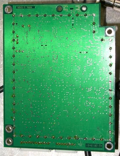
FCC ID: OW8LSMC01400 Photo 5.Internal View of EUT, Housing Opened FCC ID: OW8LSMC01400 Photo 6.Top View of Interface Board FCC ID: OW8LSMC01400 Photo 7.Bottom View of Interface Board FCC ID: OW8LSMC01400 Photo 8.Top View of Transceiver Board, Shield Installed FCC ID: OW8LSMC01400 Photo 9.Top View of Transceiver Board, Shield Removed FCC ID: OW8LSMC01400 Photo 10.Top View of Transceiver Board, Sub Shields Removed FCC ID: OW8LSMC01400 Photo 11.Bottom View of Transceiver Board
Operational Description
FCC ID: OW8LSM01400
Operational Description
FCC ID: OW8LSM01400 FCC ID: OW8LSM01400 FCC ID: OW8LSM01400 FCC ID: OW8LSM01400
Operational Description
FCC ID: OW8LSM01400 FCC ID: OW8LSM01400
RF Exposure Info
FCC ID: OW8LSMC01400 7.1 RF Safety Requirements to 2.1091 According to Section 3 of Supplement C to OET Bulletin 65, Part 15 Transmitters are categorically excluded from Routine Environmental Evaluation by measurement or precise computations unless otherwise required by the Commissions The unit under evaluation has an external antenna of 1.9 dBi gain with a measured output power output of 0.0537 Watts at the antenna terminals. The EUT may either be considered either a portable or mobile unit, depending on the end use configuration. Due to the low power of the EUT, environmental evaluation should be deemed unnecessary since the EUT’s operational frequency range is 2.4-2.4835 GHz and the ERP is considerably less than 3 Watts.
RF Exposure Info
Figure 6-3 Threaded sleeve Section 6 – LSMC Configuration CAUTION In order to comply with FCC RF exposure requirements, this device must be installed in such a way as to ensure that a minimum separation distance of 20 cm is always maintained between the antenna and all persons. Due to RF requirements, ADC recommends operating the LSMC from the vehicle only. 6a. Battery Installation STEP 1 Remove the battery cover from the backside of the LSMC case. See Figure 4-1. STEP 2 Remove the new nickel metal hydride battery from its packaging. STEP 3 Carefully install the new battery pack connector to the controller case connector. See Figure 6-1. The connector is keyed and will fit into the LSMC slot one way only. Make sure connector is firmly in place. STEP 4 Place the battery pack inside the controller case. Carefully fold and lay the connector wires in the battery case beneath the battery during installation of the battery. See Figure 6-2. STEP 5 Replace the battery cover. Slide the cover over the opening until the cover snaps into place. Note: Before using the LSMC for the first time the battery requires a charge of at least three hours. 6b. Antenna Orientation Note: The antenna should already be attached to the LSMC unit when the unit is removed from its packaging. STEP 1 Loosen the threaded sleeve. See Figure 6-3. STEP 2 Figure 6-1 Figure 6-2 Figure 6-4 Local Status Monitor/Controller Installation/Operation Manual PN XXXXXXXXXX ® Charging LED RF SYNC LED Low Batt LED Figure 6-6 Rotate the antenna into a position perpendicular to the LSMC unit. See Figure 6-4. STEP 3 Finger tighten the sleeve and connector nut so the antenna fits snugly to the LSMC unit. 6c. Vehicle DC Adapter Use Introduction the LSMC Vehicle DC Adapter has been designed to charge the unit at the same time the LSMC is active. ADC recommends that the LSMC be operated with the adapter attached unless the need arises to leave the vehicle. The LSMC will operate for approximately five hours of continuous RF SYNC on a full battery charge. STEP 1 Locate the power connector at the top of the case between the RS232 port and the antenna connector. STEP 2 Insert the adapter cord into the power connector slot in the case and plug the power adapter into the vehicle power source. See Figure 4-5. CAUTION: Use of any power adapter other than the one supplied with the LSMC may cause damage to the LSMC unit. Use only the DC adapter shipped with the LSMC. 6d. LED Functions When the battery is charging, the CHARGING LED will light and remain lit. See Figure 4-6. The CHARGING LED will turn off when battery charging is complete. Leave the battery plugged in while the charging light is on. The RF SYNC LED will blink rapidly when the LSMC is polling. When the LSMC connects to an LSM, the RF SYNC LED will appear to be continuously lit with only intermittent blinks. The LOW BATT LED will blink when the battery requires charging. Insert the adapter cord into the power connector slot in the case and plug the power adapter into the vehicle power source. Figure 6-5 Local Status Monitor/Controller Installation/Operation Manual PN XXXXXXXXXX \\Adcvs4\vol2\COMMON\00Sawyer\LSM Stuff to review\Section 6.doc Created on 05/15/00 3:24 PM Page 3 of 3 Note: Leave the DC adapter plugged in for a minimum of three hours to insure complete battery charge. Note: The RF SYNC LED and the LOW BATT LED will blink when LSMC power is on and the unit is idle.
RF Exposure Info
Section 3 – Product Overview 3a. Wireless SoftLink The Wireless SoftLink, WSL, operates in conjunction with Craft and controls LSMC via an RS232 connection. The WSL software enables technicians to address amplifiers with a local status monitor/local status monitor controller via the Craft software. The WSL can be loaded in any personal computer, or laptop. It must have Craft version 2.0 or higher version software installed to operate properly with the LSM and LSMC. ADC maintains helpdesk technical support to assist with any Craft or Wireless SoftLink software installation or operation issue. You will find complete LSM/LSMC installation/operation instructions in sections 4 and 5 of this manual. 3b. Local Status Monitor Controller (LSMC) The Local Status Monitor Controller, LSMC, is a wireless communication module connected to a PC or laptop. The main purpose for the LSMC is to facilitate a two-way wireless link between a ground located laptop and the ADC Line Extender or family of RF Amplifiers. The LSMC will allow Craft software to control the network amplifier through a wireless connection. Technicians operate the LSMC in a vehicle. For optimal performance the LSMC should remain relatively stationary during use to prevent any interruption or disconnection of the wireless link with the LSM. 3c. Local Status Monitor (LSM) The Local Status Monitor is an upgrade kit that can be installed in a Network Amplifier or Line Extender. The LSM works in conjunction with the LSM controller as a wireless link to receive commands from a laptop. Once LSM receives commands it will send commands to the ADC Line Extender or family of RF amplifiers. The LSM will function properly only with Craft version 2.0 or higher version software. The LSM will allow the operator to monitor and adjust the operating status of the RF amplifier without opening the housing. The Local Status Monitor receives the seeking transmission from the LSMC and responds to the LSMC to confirm a proper connection and to establish correspondence with the WSL. Once the LSM has established the connection with Craft, the technician can perform remotely Craft functions with the amplifier. The LSM/LSMC enables the technician to save valuable time and energy, and avoid hazardous or unpleasant weather conditions. 3d. Craft Software For questions regarding Craft software please refer to the Craft Software Installation/Operation Manual.
Test Report
ADC Broadband Communications FCC Part 15, Certification Application Local Status Monitor Controller (LSMC-01) April 23, 2000 MEASUREMENT/TECHNICAL REPORT COMPANY NAME: ADC Broadband Communications MODEL: Local Status Monitor Controller (LSMC-01) FCC ID: OW8LSMC01400 DATE: April 23, 2000 This report concerns (check one): Original grant X Class II change_____ Equipment type: Deferred grant requested per 47 CFR 0.457(d)(1)(ii)? yes_____ No X If yes, defer until:_________________ date N.A. agrees to notify the Commission by N.A. date of the intended date of announcement of the product so that the grant can be issued on that date. Report prepared by: United States Technologies, Inc. 3505 Francis Circle Alpharetta, GA 30004 Phone Number: (770) 740-0717 Fax Number: (770) 740-1508 FCC ID: OW8LSM01400 TABLE OF CONTENTS AGENCY AGREEMENT LETTER OF CONFIDENTIALITY SECTION 1 GENERAL INFORMATION 1.1 Product Description 1.2 Related Submittal(s) SECTION 2 TESTS AND MEASUREMENTS 2.1 Configuration of Tested EUT 2.2 Test Facility 2.3 Test Equipment 2.4 Modifications 2.5 Test Procedure and Results 2.6 Antenna Description 2.7 Peak Power (Antenna Conducted at Antenna Terminal) 2.8 Antenna Conducted Spurious Emissions 2.9 Peak Radiated Spurious Emissions 2.10 Average Radiated Spurious Emissions 2.11 Maximum 20 dB Bandwidth 2.12 Number of Hopping Channels 2.13 Average Time of Occupancy per Channel 2.14 Power Line Conducted Emissions for Transmitter 2.15 Radiated Emissions for Digital Device & Receiver (if Applicable) 2.16 Power Line Conducted for Digital Device & Receiver (if Applicable) SECTION 3 LABELING INFORMATION SECTION 4 BLOCK DIAGRAM(S)/ SCHEMATIC(S) SECTION 5 PHOTOGRAPHS SECTION 6 THEORY OF OPERATION SECTION 7 RF EXPOSURE INFORMATION SECTION 8 FCC ID: OW8LSM01400 USER'S MANUAL FCC ID: OW8LSMC01400 LIST OF FIGURES AND TABLES FIGURES 1)Test Configuration 2) Photograph(s) for Spurious and Fundamental Emissions Photographs(s) for Digital Device Emissions Photograph(s) for Conducted Emissions 3) Peak Power 4) Antenna Conducted Spurious Emissions 5) Peak Radiated Spurious Emissions 6) Average Radiated Spurious Emissions 7) 20 dB Bandwidth 8) Number of Hopping Channels 9) Average Time of Occupancy per Channel TABLES 1)EUT and Peripherals 2) Test Instruments 3) Peak Power Output 4) Peak Radiated Spurious Emissions 5) Average Radiated Spurious Emissions 6) 20 dB Bandwidth 7) Number of Hopping Channels 8) Average Time of Occupancy per Channel 9) Power Line Conducted Emissions for Transmitter 10) Radiated Emissions for Digital Device and Receiver 11) Power Line Conducted Emissions for Digital Device and Receiver FCC ID: OW8LSMC01400 SECTION 1 GENERAL INFORMATION FCC ID: OW8LSMC01400 GENERAL INFORMATION 1.1Product Description The Equipment Under Test (EUT) is an ADC Broadband Communications, Model Local Status Monitor Controller (LSMC-01). The ADC Broadband Communications LSMC-01 is a wireless communication module that is typically connected to a handheld smart terminal. The purpose of the LSMC is to become a two-way link between a ground located PC terminal (LST-Local Smart Terminal) and the ADC family of CATV RF Network Amplifiers so that technicians can monitor the network. The EUT is designed to operate on one of two different channel sets. Please refer to the following letter from ADC Broadband Communications. FCC ID: OW8LSMC01400 FCC ID: OW8LSMC01400 1.2Related Submittal(s)/Grant(s) The EUT will be used with part of a system to send/receive data. The transceiver presented in this report will be used with another transceiver, which has been submitted under FCC ID: OW8LSM01400 The EUT is subject to the following authorizations: a) Certification as a transmitter b) Verification as a digital device (Class A) The information contained in this report is presented for the certification & verification authorization(s) for the EUT. FCC ID: OW8LSMC01400 SECTION 2 TESTS AND MEASUREMENTS FCC ID: OW8LSMC01400 TEST AND MEASUREMENTS 2.1 Configuration of Tested System The sample was tested per ANSI C63.4, Methods of Measurement from Low-Voltage Electrical and Electronic Equipment in the Range of 9 kHz to 40 GHz (1992). Conducted and radiated emissions data were taken with the test receiver or spectrum analyzer's resolution bandwidth adjusted to 9 kHz and 120 kHz, respectively. All measurements are peak unless stated otherwise. The video filter associated with the spectrum analyzer was off throughout the evaluation process. Interconnecting cables were manipulated as necessary to maximize emissions. Interconnecting cables were manipulated as necessary to maximize emissions. A block diagram of the tested system is shown in Figure 1. Test configuration photographs for spurious and digital device emissions are shown in Figure 2. The sample used for testing was received by U.S. Technologies on February 23, 2000 in good condition. 2.2 Test Facility Testing was performed at US Tech's measurement facility at 3505 Francis Circle, Alpharetta, GA. This site has been fully described and submitted to the FCC, and accepted in their letter marked 31040/SIT. Additionally this site has also been fully described and submitted to Industry Canada (IC), and has been approved under file number IC2982. 2.3 Test Equipment Table 2 describes test equipment used to evaluate this product. 2.4 Modifications Two modifications were made by ADC Broadband Communications in order to bring the EUT into compliance with FCC Part 15 limits for the transmitter portion of the EUT and the Class A Digital Device Requirements. Please refer to the following letter provided by ADC Broadband Communications. FCC ID: OW8LSMC01400 FCC ID: OW8LSMC01400 FIGURE 1a TEST CONFIGURATION (TRANSMIT/RECEIVE CONFIGURATION) DC Power Supply Palmtop (Simulating a LST) Battery 10' u 8’ s LSMC (EUT) Antenna 6'u 120 VAC 60 Hz 2'u coiled Power Supply 6'u 120 VAC 60 Hz FCC ID: OW8LSMC01400 FIGURE 1b TEST CONFIGURATION (CHARGE MODE CONFIGURATION) DC Power Supply (Simulating Car C onnecti on) …
Text truncated - open the document above for the full version.
Test Report
FCC ID: OW8LSMC01400 2.9 Peak Radiated Spurious Emission in the Frequency Range 30 -25000 MHz (FCC Section 15.247(c)) The EUT was hop-stopped and when possible placed into a continuous transmit mode of operation. A preliminary scan was performed on the EUT to determine frequencies that were caused by the transmitter portion of the product. Significant emissions that fell within restricted bands were then measured on an OAT’s site. Radiated measurements below 1 GHz were tested with a RBW = 120 kHz. Radiated measurements above 1 GHz were measured using a RBW = VBW = 1 MHz. The results of peak radiated spurious emissions falling within restricted bands are given in Table 4a (low), Table 4b, (mid), Table 4c (high) and Figure 5a-5c (low), Figure 5d (mid) and Figure 5e (high). FCC ID: OW8LSMC01400 Figure 5a Peak Radiated Spurious Emission 15.247(c) Low FCC ID: OW8LSMC01400 Figure 5b Peak Radiated Spurious Emission 15.247(c) Low FCC ID: OW8LSMC01400 Figure 5c Peak Radiated Spurious Emission 15.247(c) Low FCC ID: OW8LSMC01400 Figure 5d Peak Radiated Spurious Emission 15.247(c) Mid FCC ID: OW8LSMC01400 Figure 5e Peak Radiated Spurious Emission 15.247(c) High FCC ID: OW8LSMC01400 TABLE 4a PEAK RADIATED SPURIOUS EMISSIONS (Low) Freq. (GHz) Test Data* (dBm) @3m Amp. Gain (dB) Antenna Factor (dB) Cable Loss (dB) Results (uV/m) @3m FCC Limits (uV/m) @3m 2.68238-75.4**-31.24.12202.95000 4.80310-58.034.235.67.9735.95000 5.08443-61.534.135.28.3559.25000 TABLE 4b PEAK RADIATED SPURIOUS EMISSIONS (Mid) Freq. (GHz) Test Data* (dBm) @3m Amp. Gain (dB) Antenna Factor (dB) Cable Loss (dB) Results (uV/m) @3m FCC Limits (uV/m) @3m 4.87898-59.934.134.88.1614.95000 TABLE 4c PEAK RADIATED SPURIOUS EMISSIONS (High) Freq. (GHz) Test Data* (dBm) @3m Amp. Gain (dB) Antenna Factor (dB) Cable Loss (dB) Results (uV/m) @3m FCC Limits (uV/m) @3m 4.9591-53.234.135.08.31409.15000 * = Data adjusted by + 1 dB for high pass filter ** = Data taken at 1 meter, without amplifier and high pass filter to achieve proper dynamic range. Therefore this reading has been adjusted by –9.54 for 1 to 3 meter correction. SAMPLE CALCULATION: RESULTS (uV/m @ 3m) = Antilog ((-58.0 - 34.2 + 34.6 + 7.9 + 107)/20) = 735.9 CONVERSION FROM dBm TO dBuV = 107 dB Test Results Reviewed By Signature: Name: Tim R. Johnson FCC ID: OW8LSMC01400 2.10 Average Spurious Emission in the Frequency Range 30 - 25000 MHz (FCC Section 15.247(c)) The results of average radiated spurious emissions falling within restricted bands are given in Table 5a (low), Table 5b, (mid), Table 5c (high) and Figure 6a-6c (low), Figure 6d (mid) and Table 6e (high). FCC ID: OW8LSMC01400 Figure 6a Average Radiated Spurious Emission 15.247(c) Low FCC ID: OW8LSMC01400 Figure 6b Average Radiated Spurious Emission 15.247(c) Low FCC ID: OW8LSMC01400 Figure 6c Average Radiated Spurious Emission 15.247(c) Low FCC ID: OW8LSMC01400 Figure 6d Average Radiated Spurious Emission 15.247(c) Mid FCC ID: OW8LSMC01400 Figure 6e Average Radiated Spurious Emission 15.247(c) High FCC ID: OW8LSMC01400 TABLE 5a AVERAGE RADIATED SPURIOUS EMISSIONS (Low) Freq. (GHz) Test Data* (dBm) @3m Amp. Gain (dB) Antenna Factor (dB) Cable Loss (dB) Results (uV/m) @3m FCC Limits (uV/m) @3m 2.68238-49.9-31.24.12.4500 4.80310-79.834.235.67.966.8500 5.08443-87.234.135.28.328.8500 TABLE 5b AVERAGE RADIATED SPURIOUS EMISSIONS (Mid) Freq. (GHz) Test Data* (dBm) @3m Amp. Gain (dB) Antenna Factor (dB) Cable Loss (dB) Results (uV/m) @3m FCC Limits (uV/m) @3m 4.87898-78.634.134.88.172.4500 TABLE 5c AVERAGE RADIATED SPURIOUS EMISSIONS (High) Freq. (GHz) Test Data* (dBm) @3m Amp. Gain (dB) Antenna Factor (dB) Cable Loss (dB) Results (uV/m) @3m FCC Limits (uV/m) @3m 4.9591-74.834.135.08.3117.5500 * = Data adjusted by + 1dB for high pass filter and 20 log (0.14) = –17.1 dB for w orse case duty cycle. ** = Data taken at 1 meter, w ithout amplifier and high pass filter to achieve proper dynamic range. Therefore this reading has been adjusted by –9.54 for 1 to 3 meter correction. SAMPLE CALCULATION: RESULTS (uV/m @ 3m) = Antilog…
Text truncated - open the document above for the full version.
Contact Information
Applicant
Steve Kim
steve_kim.adc.com678-584-7212
Technical Contact
United States TechnologiesTimothy R Johnson
[email protected]770-740-0717
3505 Francis Circle · Alpharetta, Georgia · United States
Non-Technical Contact
United States TechnologiesTimothy R Johnson
[email protected]770-740-0717
Test Firm
US TechSandy McEnery
Technical Specifications
| # | Rule Parts | Frequency Range | Power Output |
|---|---|---|---|
| 1 | 15C | 2.40 GHz - 2.48 GHz | 53.70 mW |
Other Applications from ADC Broadband Communications
OW8LSM01400
Jul 05, 2000Local Status Monitor
Equipment Class
DSS - Part 15 Spread Spectrum Transmitter