OWGWS900RXDiaper Wetness Sensor for Home Care
Excel Engineering (HK) Co Ltd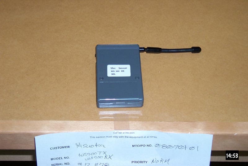
Click to zoom
Application Details
- Equipment Class
- CYY - Communications Receiver used w/Pt 15 Transmitter
- Date of Grant
- Jun 23, 2002
- Application Purpose
- Original Equipment
- Date of Application
- Jun 23, 2002
- Equipment Note
- Diaper Wetness Sensor for Home Care
- Frequency Range
- 907.76200000 - 907.76200000
- Country
- Hong Kong
Documents & Files
Document Text
Text extracted from the exhibit documents filed with the FCC. Open a document above to read the original.
Users Manual
WS900 Diaper Wetness Sensor for Home Care User's Manual 1/9 This device complies with part 15 of the FCC Rules. Operation is subject to the following two conditions: 1)This device may not cause harmful interference, and 2)This device must accept any interference received, including interference that may cause undesired operation. Any changes or modifications not expressly approved by Excel Engineering (HK) Co. Ltd. could void the user's authority to operate the equipment. Item Modulation Type Wetness Sensing Spec. FM Band Volume Sensor, Resistance Sensor Comment Frequency Capacity Deviation Crystal Oscillator Current ±10ppm Frequency 907.762MHz Within FCC Requirment(Less Than 5000uV/m) Range In-Door Approx. 50m Oscillation Type Power Supply 3V(AAA x 2) Battery Life Approx. 1 Month 1.Specification FCC Automatic Levels 15.231(e) Antenna LED Indicator Case Built-In Operation Indicator, Battery Indicator ABS Operating Temp. 0~45°C Modulation Speed Sensor Connection 6-Line Modular 500bps 2.Function Max ID Sensor Set-up 256 ID Set-up Type Type Method Type Condition Written in ROM Auto Wet Mode---Blink at 3 sec. cycle Operating---Automatically illuminates after installing sensor and blink at 6 sec. cycle Low Battery---Blink at 1 sec. cycle LED Indicator LED Method -------- Switch Sensor Pad & Tape Adapter Fixed ■Parts Description & Function Wetness Sensor (Sensor Side) Apply this surface to the diaper with double-faced tape. CAUTION ●If the wrong side is applied, the sensor does not work properly. Sensor Adapter R03 ( AAA) R03 ( AAA) ②Sensor Jack connects tape adapter or sensor pad. ①LED Indicator indicates conditions of transmitter. ③Battery Case holds 2 AAA batteries. ④Battery Case Cover ■How to Set-Up Sensor Adapter ■How to Set-Up Sensor Tape Install the sensor adapter to the sensor tape as below. Please make sure that the snap fasteners touch the electrodes; otherwise, it may not sense wetness. Electrodes CAUTION ●Attach the side of the tape to the snap fastener. Attaching to the female buttons may cause an error. ●Use more than 16 inches long sensor tape. Using shorter sensor tape may cause an error. ●Make new holes on tape every installation. Reusing holes may cause an error. 3. Wrap with the center cover. 2. Wrap the diaper with its side cover and fasten with Velcro fastener. Fold back the transmitter on the cover. ■How to Apply to Diaper 1. Apply the sensor tape between two layers of cloth diaper. ・Using Sensor Tape 注意 注意 Face the blue side of the sensor tape to skin. Facing the wrong side may cause an error. The sensor tape is only for one time use. Discard the used tape as combustible. Insert the plug into the jack all the way until the terminal latches into the transmitter's receptor. Snap fastener for fixing the Sensor Tape LED will blink when it is set correctly. CAUTION CAUTION ■How to Set-Up Sensor Pad CAUTION ●Attaching the terminal upside down will cause an error. After connection, make sure LED is blinking. ■How to Apply to the Diaper 1. Attach the sensor pad to the diaper using double-faced tape. Attach the grey side of the pad to the diaper. Attaching the wrong side may cause an error. Change double-faced tape every day. Pre-used tape may cause an error. 3. Wrap with the center cover. 2. Wrap the diaper with its side cover and fasten with Velcro fastener. Fold back the transmitter on the cover. You can also secure the transmitter with a clip. CAUTION If the string touches skin, the sensor may not work properly. Keep the sensor string from touching skin. Attach the sensor side of the pad to the diaper. Make sure the sensor is well adhered to the diaper. ■Storage Caution ●When storing, detach the sensor pad from the transmitter, or remove batteries. Leaving the rear side of the sensor pad on a metal surface may cause malfunction. When not in use, make sure that the rear side of the pad does not contact a metal surface. Insert the plug into the jack all the way until the plug latches into the transmitter's receptor. LED will blink when it is set correctly CAUTION CAUTION CAUTION Item ID Channel Spec. Select 1 of 256 Comment Receiving Type Within FCC Sensitivity FM Band Receiving Frequency907.762MHz Indoor Approx. 50m 100dBu(12dBSINAD) Unwanted Emission Power Supply3V(AAA × 2) Battery LifeApprox. 1 Month 1.Specification Antenna LED Indicator Case 1/2λ(External) Operation Indicator, Receiving Indicator ABS L100×W59×H19.5 Operating Temp.0~45°C Written in ROM AlarmSwitch Hi-Low(Volume Hi-Low) VibratorIntermittent Vibration Alkaline AAA Battery x 2 Modified the existing case Can swivel 2.Function Max D Alarm Set-up Vibrator Set-up 256 ID Set-up Type Type Method Type Condition Written in ROM Side-Mounted Switch Wet Mode---LED (Green) illuminates Operating---LED(Red)blinks at every 1.5 sec. Low Battery---LED(Red)blinks at every 1 sec. Method Type LED Indicator LED Method -------- Hi-Low Fixed Alarm Mode Side-Mounted Switch Vibration Alarm - Low Alarm - High Alarm ■Parts Description & Function ①Antenna Keep the antenna straight up for better reception ⑤Alarm Mode Switch Knob switches between vibration, low alarm, and high alarm. (3 positions) ④Power Switch ON to use. OFF to quit or to reset the sensor. ⑥Battery Case Cover R03 ( AAA) R03 ( AAA) ⑦Battery Case holds 2 AAA batteries. ③Operation Indicator You can check that the receiver is working when the red light blinks at every 1.5 sec. When low battery, red light blinks at every 1 sec. . ②Receiving Indicator illuminates for receiving Wet Signal from transmitter Does LED blink?If no, check batteries and every connection. break down of the wire?Use a new tape adapter. Is there dust in snap fastener?Remove dust. Do batteries have power?Check LED and change batteries. Are you operating within the range? Keep the distance between the transmitter and receiver within 160ft, when use. Is the battery case broken?If yes, call service department for repair. Is the transmitter case broken?If yes, call service department for repair. Is the right si…
Text truncated - open the document above for the full version.
Users Manual
WS900 Diaper Wetness Sensor for Home Care User's Manual 1/9 This device complies with part 15 of the FCC Rules. Operation is subject to the following two conditions: 1)This device may not cause harmful interference, and 2)This device must accept any interference received, including interference that may cause undesired operation. Any changes or modifications not expressly approved by Excel Engineering (HK) Co. Ltd. could void the user's authority to operate the equipment. Item Modulation Type Wetness Sensing Spec. FM Band Volume Sensor, Resistance Sensor Comment Frequency Capacity Deviation Crystal Oscillator Current ±10ppm Frequency 907.762MHz Within FCC Requirment(Less Than 5000uV/m) Range In-Door Approx. 50m Oscillation Type Power Supply 3V(AAA x 2) Battery Life Approx. 1 Month 1.Specification FCC Automatic Levels 15.231(e) Antenna LED Indicator Case Built-In Operation Indicator, Battery Indicator ABS Operating Temp. 0~45°C Modulation Speed Sensor Connection 6-Line Modular 500bps 2.Function Max ID Sensor Set-up 256 ID Set-up Type Type Method Type Condition Written in ROM Auto Wet Mode---Blink at 3 sec. cycle Operating---Automatically illuminates after installing sensor and blink at 6 sec. cycle Low Battery---Blink at 1 sec. cycle LED Indicator LED Method -------- Switch Sensor Pad & Tape Adapter Fixed ■Parts Description & Function Wetness Sensor (Sensor Side) Apply this surface to the diaper with double-faced tape. CAUTION ●If the wrong side is applied, the sensor does not work properly. Sensor Adapter R03 ( AAA) R03 ( AAA) ②Sensor Jack connects tape adapter or sensor pad. ①LED Indicator indicates conditions of transmitter. ③Battery Case holds 2 AAA batteries. ④Battery Case Cover ■How to Set-Up Sensor Adapter ■How to Set-Up Sensor Tape Install the sensor adapter to the sensor tape as below. Please make sure that the snap fasteners touch the electrodes; otherwise, it may not sense wetness. Electrodes CAUTION ●Attach the side of the tape to the snap fastener. Attaching to the female buttons may cause an error. ●Use more than 16 inches long sensor tape. Using shorter sensor tape may cause an error. ●Make new holes on tape every installation. Reusing holes may cause an error. 3. Wrap with the center cover. 2. Wrap the diaper with its side cover and fasten with Velcro fastener. Fold back the transmitter on the cover. ■How to Apply to Diaper 1. Apply the sensor tape between two layers of cloth diaper. ・Using Sensor Tape 注意 注意 Face the blue side of the sensor tape to skin. Facing the wrong side may cause an error. The sensor tape is only for one time use. Discard the used tape as combustible. Insert the plug into the jack all the way until the terminal latches into the transmitter's receptor. Snap fastener for fixing the Sensor Tape LED will blink when it is set correctly. CAUTION CAUTION ■How to Set-Up Sensor Pad CAUTION ●Attaching the terminal upside down will cause an error. After connection, make sure LED is blinking. ■How to Apply to the Diaper 1. Attach the sensor pad to the diaper using double-faced tape. Attach the grey side of the pad to the diaper. Attaching the wrong side may cause an error. Change double-faced tape every day. Pre-used tape may cause an error. 3. Wrap with the center cover. 2. Wrap the diaper with its side cover and fasten with Velcro fastener. Fold back the transmitter on the cover. You can also secure the transmitter with a clip. CAUTION If the string touches skin, the sensor may not work properly. Keep the sensor string from touching skin. Attach the sensor side of the pad to the diaper. Make sure the sensor is well adhered to the diaper. ■Storage Caution ●When storing, detach the sensor pad from the transmitter, or remove batteries. Leaving the rear side of the sensor pad on a metal surface may cause malfunction. When not in use, make sure that the rear side of the pad does not contact a metal surface. Insert the plug into the jack all the way until the plug latches into the transmitter's receptor. LED will blink when it is set correctly CAUTION CAUTION CAUTION Item ID Channel Spec. Select 1 of 256 Comment Receiving Type Within FCC Sensitivity FM Band Receiving Frequency907.762MHz Indoor Approx. 50m 100dBu(12dBSINAD) Unwanted Emission Power Supply3V(AAA × 2) Battery LifeApprox. 1 Month 1.Specification Antenna LED Indicator Case 1/2λ(External) Operation Indicator, Receiving Indicator ABS L100×W59×H19.5 Operating Temp.0~45°C Written in ROM AlarmSwitch Hi-Low(Volume Hi-Low) VibratorIntermittent Vibration Alkaline AAA Battery x 2 Modified the existing case Can swivel 2.Function Max D Alarm Set-up Vibrator Set-up 256 ID Set-up Type Type Method Type Condition Written in ROM Side-Mounted Switch Wet Mode---LED (Green) illuminates Operating---LED(Red)blinks at every 1.5 sec. Low Battery---LED(Red)blinks at every 1 sec. Method Type LED Indicator LED Method -------- Hi-Low Fixed Alarm Mode Side-Mounted Switch Vibration Alarm - Low Alarm - High Alarm ■Parts Description & Function ①Antenna Keep the antenna straight up for better reception ⑤Alarm Mode Switch Knob switches between vibration, low alarm, and high alarm. (3 positions) ④Power Switch ON to use. OFF to quit or to reset the sensor. ⑥Battery Case Cover R03 ( AAA) R03 ( AAA) ⑦Battery Case holds 2 AAA batteries. ③Operation Indicator You can check that the receiver is working when the red light blinks at every 1.5 sec. When low battery, red light blinks at every 1 sec. . ②Receiving Indicator illuminates for receiving Wet Signal from transmitter Does LED blink?If no, check batteries and every connection. break down of the wire?Use a new tape adapter. Is there dust in snap fastener?Remove dust. Do batteries have power?Check LED and change batteries. Are you operating within the range? Keep the distance between the transmitter and receiver within 160ft, when use. Is the battery case broken?If yes, call service department for repair. Is the transmitter case broken?If yes, call service department for repair. Is the right si…
Text truncated - open the document above for the full version.
External Photos
NCEE R021802-01 FCC ID:OWGWS900 Page 19 of 22 Figure 13 WS900Rx, front Figure 14 ES900Rx, back
Test Report
R021802-01B FCC ID:OWGWS900Tx/Rx NCEE NEBRASKA CENTER FOR EXCELLENCE IN ELECTRONICS 4740 Discovery Drive Lincoln, NE 68521 402-472-5880 Amendment to Test Report R021802-01A Company: Excel Engineering Suite 368 3655 Torrance Blvd. Torrance, CA, USA 90503-4868 Contact: Rocky Sawada Product: WS900 FCC ID: OWGWS900Tx/Rx Test Report No: R021802-01B APPROVED BY: Steve Cass _________________________ General Manager Doug Kramer _________________________ Test Engineer DATE: 15 June 2002 Total Pages: 19 The Nebraska Center for Excellence in Electronics (NCEE) authorizes the above named company to reproduce this report provided it is reproduced in its entirety for use by the company’s employees only. Any use that a third party makes of this report, or any reliance on or decisions made based on it, are the responsibility of such third parties. NCEE accepts no responsibility for damages, if any, suffered by any third party as a result of decisions made or actions based on this report. This report applies only to the items tested. NCEE is a FCC registered lab. Registration #100875 NCEE R021802-01B FCC ID:OWGWS900Tx/Rx Page 2 of 19 Table of Contents 1.0 Summary of test results 1.1 Reason for Amended Report 1.2 Test Results 1.3 Test Methods 1.3.1 Radiated Emissions 2.0 Description 2.1 Equipment under test 2.1.1 Identification 2.1.2 EUT received date 2.1.3 EUT tested dates 2.1.4 Manufacturer 2.1.5 Serial number 2.2 Laboratory description 2.3 Special equipment or setup 3.0 Test equipment used 4.0 Detailed Results 4.1 FCC Part 15.109 Radiated Emissions for Class ‘B’ devices, Rx 4.2 FCC Part 15.203, Tx 4.3 FCC Part 15.249 Radiated Emissions, Tx Appendix A – Test setup photos Appendix B – Emissions peak values Appendix C – External photos NCEE R021802-01B FCC ID:OWGWS900Tx/Rx Page 3 of 19 1.0 Summary of test results 1.1 Reason for Amended Report The report has been amended to allow for the reporting of data for OWGWS900TX and OWGWS900RX. 1.2 Test Results Test Test Specification Results CFR 47, FCC Part 15.109 Part 15.109, Class B Complies CFR 47, FCC Part 15.203 Part 15.203 Complies CFR 47, FCC Part 15.249 Part 15.249 Complies 1.3 Test Methods 1.3.1 Radiated Emissions All measurements were taken at a distance of 3 meters using the methods outlined in ANSI/IEEE C63.4, 2001. Measurements were taken from 30MHz to 1Gz, then from 1GHz to 10GHz. All data presented is the measured results with any applicable correction factors applied via the test software. The 3 orthogonal axes of the WS900TX were examined in order to maximize the emissions. 2.0 Description 2.1 Equipment under test The WS900 consists of the wetness sensor/transmitter module and remote receiver unit. The transmitter emits a signal only when the sensor detects moisture. The receiver picks up the signal and an alarm tone is activated. The tone stops when the transmitter stops transmitting. On the unit tested, there was no provision for non-battery powered operation. 2.1.1 Identification: WS900Tx wetness sensor WS900Rx wetness receiver 2.1.2 EUT received date: 14 February 2002 2.1.3 EUT tested dates: 1 st , 4 th , 7 th , and 8 th March 2002 2.1.4 Manufacturer: Excel Engineering, HK 2.1.5 Serial number: WS900Tx wetness sensor, SN: 78 WS900Rx wetness receiver, SN: 12 NCEE R021802-01B FCC ID:OWGWS900Tx/Rx Page 4 of 19 2.2 Laboratory description All testing was performed at the NCEE Lincoln facility, which is a FCC registered lab. This site has been fully described in a report submitted to the FCC, and accepted in a letter dated May 4, 2001. Laboratory environmental conditions varied slightly throughout the tests: Relative humidity of 46 ± 5% Temperature of 21 ± 3° Celsius 2.3 Special equipment or setup The EUT was tested using new AAA batteries. A modified test probe was used so that the WS900Tx would continuously transmit. An actual probe was examined and no differences in the emission spectrum or emissions in excess of the limits were found to be coming from the EUT. 3.0 Test equipment used Serial # Manufacturer Model Description Last cal. 1647 EMCO 3142B Biconilog antenna 25-May-01 6415 EMCO 3115 DRG Horn 31-May-01 100037 Rohde & Schwarz ESIB26 EMI Test Receiver 11-Jun-01 082001/003 Rohde & Schwarz TS-PR18 Preamplifier 10-Aug-01 2575 Rohde & Schwarz ES-K1 Software v1.60 N/A NCEE R021802-01B FCC ID:OWGWS900Tx/Rx Page 5 of 19 4.0 Detailed Results 4.1 FCC Part 15.109 Radiated Emissions for Class ‘B’ devices, Rx The WS900Rx portion was tested in its standard configuration, with new batteries. Figures 1 and 2, in Appendix A, show the test setup used. The EUT was rotated and the mast was raised from 1 meter to 4 meters to find the highest emissions. No emissions were found to be in excess of the limits for Class ’B’ devices found in CFR 47, Part 15.109. The results can be seen in figures 5 and 6 in Appendix B. The highest peak values, below 1GHz, and the highest average values, above 1GHz, are shown below. The antenna on the receiver is attached via a screw that is enclosed within the case of the EUT. 4.2 FCC Part 15.203, Tx The WS900Tx antenna is copper rod that is soldered to the circuit board of the EUT and is completely enclosed within the unit. 4.3 FCC Part 15.249 Radiated Emissions, Tx The WS900Tx was tested for compliance to the limits in CFR 47, Part 15.249. Figures 3 and 4 show the setup used. Figures 7 through 10 show the plots of the results. The first 5 harmonics and the fundamental measurement are shown in the first table below, the remaining harmonics were indistinguishable from the noise floor. The second table contains the highest emissions while the EUT was not transmitting. No emissions beyond the carrier frequency exceed the general radiated emissions limit as set forth in 15.209. Frequency Corrected Level Polarisation MHzdBμV/m 33.06738627.3H,PK 31.7337426.61V,PK 3026.49V,PK 34.00093826.44H,PK 33.33411526.31V,PK 30.80018826.07V,PK 30.93355225.97H,PK 30.40009425.9V,PK 34.26766725.89V,PK 34.53439725.89H,PK 31.20028125.81H,PK 700042.14V,AV …
Text truncated - open the document above for the full version.
Test Setup Photos
NCEE R021802-01 FCC ID:OWGWS900 Page 8 of 22 Figure 1 WS900Rx, Test setup Figure 2 WS900Rx, Test setup
Contact Information
Applicant
Yasuoka Katsunori(Director)
Technical Contact
American Excel EngineeringRocky Swada
[email protected]310-543-9303
3655 Torrance Blvd. Suite 368 · Torrance, California · United States
Non-Technical Contact
American Excel EngineeringRocky Swada
[email protected]310-543-9303
Test Firm
Nebraska Center for Excellence in ElectronicsSteve Cass
Technical Specifications
| # | Rule Parts | Frequency Range | Power Output |
|---|---|---|---|
| 1 | 15B | 907.762 MHz - 907.762 MHz | - |
Other Applications from Excel Engineering (HK) Co Ltd
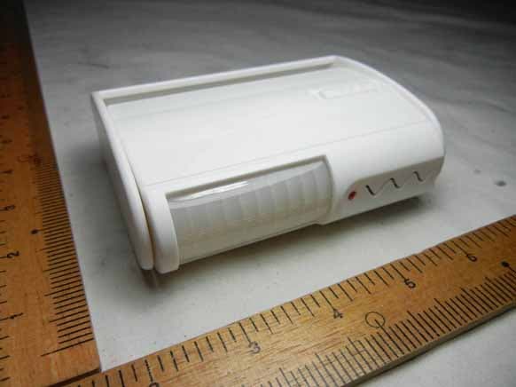
OWGSP2302011
Dec 12, 2011Motion Detector
Equipment Class
DXX - Part 15 Low Power Communication Device Transmitter
OWGNC-100-07
Oct 21, 2007Wireless Nurse Call Interface (303.8MHz Tx)
Equipment Class
DSC - Part 15 Security/Remote Control Transmitter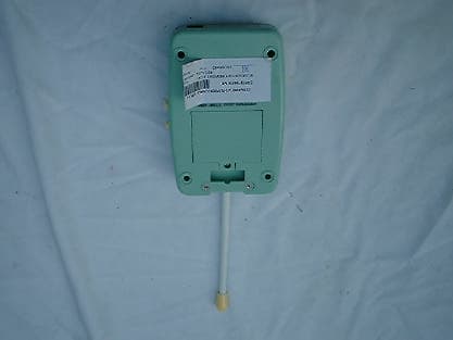
OWGNRM180
Mar 03, 2003Remote Control Toy Transmitter
Equipment Class
DXX - Part 15 Low Power Communication Device Transmitter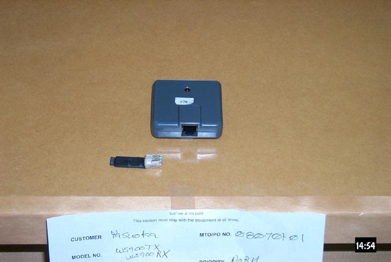
OWGWS900TX
Jun 23, 2002Diaper Wetness Sensor for Home Care
Equipment Class
DXX - Part 15 Low Power Communication Device Transmitter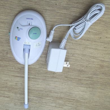
OWGTFY3808
Nov 05, 2000Safe & Sounds Monitor
Equipment Class
DXX - Part 15 Low Power Communication Device Transmitter