OX4927027 MHz Remote Control Car - TX
Ritvik Holdings Inc.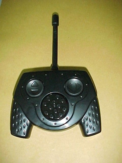
Click to zoom
Application Details
- Equipment Class
- DXX - Part 15 Low Power Communication Device Transmitter
- Date of Grant
- Jun 06, 2001
- Application Purpose
- Original Equipment
- Date of Application
- Jun 06, 2001
- Equipment Note
- 27 MHz Remote Control Car - TX
- Frequency Range
- 26.96000000 - 27.28000000
- Company
- Ritvik Holdings Inc.
- Country
- Canada
Documents & Files
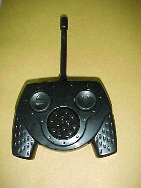
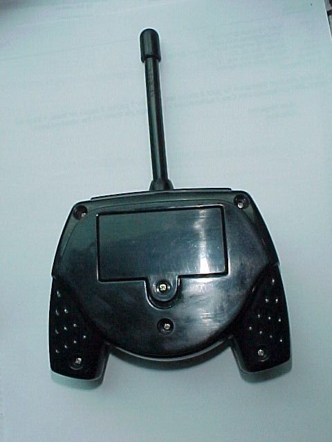
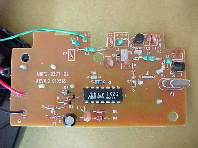
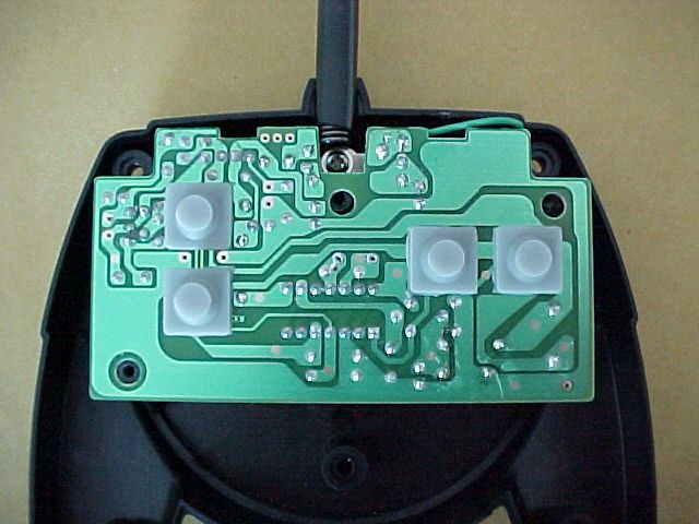
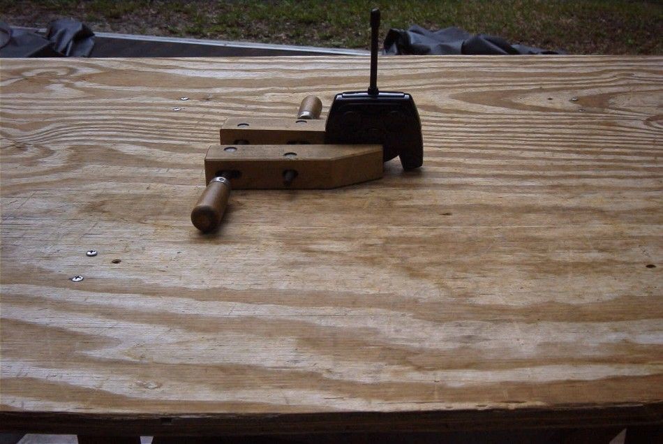
Document Text
Text extracted from the exhibit documents filed with the FCC. Open a document above to read the original.
Users Manual
INSTRUCTIONS MODE D’EMPLOI INSTRUCCIONES CAUTION TO AVOID BATTERY LEAKAGE AVERTISSEMENT POUR ÉVITER LA FUITE DES PILES ADVERTENCIA PARA EVITAR QUE LAS PILAS SE SULFATEN MOTORIZED BASE BASE MOTORISÉE BASE MOTORIZADA TRANSMITTER TÉLÉCOMMANDE CONTROL REMOTO SOUND MODULE MODULE SONORE ????????? 1. Be sure to install the batteries correctly (see diagram) andalways follow the toy and battery manufacturers’ instructions.2. Do not mix used and new batteries together. Do not mix alka-line, standard (carbon zinc), or rechargeable (nickel cadmium)batteries. Only batteries of the same type are to be used.3. Always remove exhausted or dead batteries from the productand always remove batteries before extended storage.4. Rechargeable batteries are only to be changed under adultsupervision (if removable).5. Non rechargeable batteries are not to be recharged.6. The supply terminal is not to be short circuited.7. Batteries are to be inserted according to the correct polarity.(see diagram)8. How to remove and insert replaceable batteries. (see diagram) 1. S’assurer d’installer les piles ou accumulateurs correctement(voir le diagramme) en suivant toujours les instructions du fabri-cant du jouet et des piles.2. Ne pas mélanger des piles neuves et usagées. Ne pasmélanger des piles alcalines, standards (carbone-zinc) ourechargables (nickel-cadmium)3. Les piles et accumulateurs usagés doivent être enlevés dujouet, avant le rangement pour une longue période.4. Les accumulateurs doivent être enlevés du jouet avant d’êtrechargés et les accumulateurs ne doivent être chargés que sousla surveillance d’un adulte.5. Ne jamais recharger des piles (non-rechargeables).6. Les bornes d’une pile ou d’un accumulateur ne doivent pasêtre mises en court-circuit.7. Les piles et accumulateurs doivent être mises en place enrespectant la polarité. (voir le diagramme)8. Comment enlever et mettre en place les piles ou accumula-teurs remplaçables. (voir le diagramme) 1. Asegúrese de colocar las pilas correctamente (ver diagrama) y de seguir las instrucciones de los fabricantes del juguete y de las pilas.2. No mezclar pilas nuevas con pilas usadas nitampoco acumu-ladores (niquel cadmio) o pilas de tipos diferentes (alcalina, car-bon-cinc). Siempre utilice pilas del mismo tipo.3. Siempre retire las pilas acabadas o gastadas del juguete,especialmente si piensa guardarlo por tiempo prolon gado.4. Un adulto debe recargar las pilas recargables (siempre que laspueda retirar).5. No recargue pilas que no sean recargables.6. No origine cortocircuitos en los bornes del compartimiento delas pilas.7. Coloque las pilas respetando la polaridad correcta. (ver dia-grama)8. Cómo sacar e introducir las pilas reemplazables. (ver diagra Please read these instructions carefully and keep them forfuture reference.Requires two size AA 1.5 V alkaline batteries in the motorizedbase (not included).Requires one 6R61-9-volt alkaline battery in the transmitter (not included).Requires three size AA 1.5 V alkaline batteries in the sound mo-dule (included). Important :Radio interference can occur if more than one remotecontrol car or other radio device is operating on the samefrequency. Radio interference can cause your MACHINES™ RADIO CONTROL to run erratically. For bestperformance, please be sure to maintain a distance fromradio devices such as nursery monitors, cordless phonesor other remote control cars on the same frequency aswell as high voltage electrical wires, reinforced concretebuildings and CB radios.Note : This device may not cause interference, and this devicemust accept any interference, including interference that maycause undesired operation of the device. However, the manufac-turer is not responsible for any radio or TV interference causedby unauthorized modifications to this equipment.Such modifications could void the user’s authority to operate theequipment.Carrier Frequency 27.145 MHzField Strength 74.1 dBuV / mMeasurement Distance 3 m Il est recommandé de lire attentivement ce feuillet avant lapremière utilisation et de le conserver pour référence future.La base motorisée utilise deux piles alcalines AA-1.5 V (non comprises).La télécommande utilise une pile alcaline 6R61-9V (non comprise).La base sonore utilise trois piles alcalines AA-1.5 V (incluses).Important :Des interférences radio peuvent se produire lorsque plusieursappareils utilisent la même fréquence et peuvent perturber lefonctionnement de votre MACHINES™ RADIO CONTROL.Pour une performance optimale, assurez-vous de maintenir unebonne distance avec d’autres appareils à commande radio telsque : moniteurs pour bébé, téléphones sans fil ou autreappareils télécommandés utilisant la même fréquence, demême que les fils électriques à haute tension, édifices de bétonarmé ou émetteurs-récepteurs CB.NOTE : Ce dispositif ne doit pas produire de brouillage et doitaccepter tout brouillage radioélectrique, même si ce brouillageest susceptible de compromettre son fonctionnement.Toutefois, le fabricant n’est pas responsable d’interférencesradio ou TV provoquées par des modifications non autoriséesdu jouet. De telles modifications pourraient altérer la capacitéde l’utilisateur à faire fonctionner cet appareil.Fréquence porteuse 27.145 MHzIntensité de champ 74.1 dBuV / mDistance de mesure 3 m Sírvase leer estas instrucciones y guardarlas para referen-cia futura.La base motorizada requiere 2 pilas alcalinas AA 1,5 V(no incluidas).El control remoto requiere una pila alcalina 6R61 de 9 voltios (no incluida).La base motorizada requiere 3 pilas alcalinas AA 1,5 V (no incluidas). Importante:Es posible que al operar más de un vehículo a control remoto uotro aparato de radio en la misma frecuencia se produzca interfer-encia radial. La interferencia radial puede causar la operaciónerrática de su vehículo MACHINES™ RADIO CONTROL. Para que elvehículo funcione mejor, manténgalo alejado de aparatos de radio,como por ejemplo monitores para bebés, teléfonos inalámbricos,otros vehículos a control remoto operados en la mis…
Text truncated - open the document above for the full version.
ID Label/Location Info
FCCID: OX49270 This device complies with Part 15 of the FCC Rules. Operation of this device is subject to the following two conditions: (1) This device may not cause harmful interference, and (2) This device must accept any interference received, including interference that may cause undesired operation. MEGA BLOKS 9270 CANADA 210
ID Label/Location Info
FCCID: OX49270 This device complies with Part 15 of the FCC Rules. Operation of this device is subject to the following two conditions: (1) This device may not cause harmful interference, and (2) This device must accept any interference received, including interference that may cause undesired operation. MEGA BLOKS 9270 CANADA 210
Test Report
TABLE OF CONTENTS APPLICANT: RITVIK HOLDINGS INC. FCC ID: OX49270 TEST REPORT CONTAINING: PAGE 1......TEST EQUIPMENT LIST AND TEST PROCEDURE PAGE 2......TEST PROCEDURE CONTD. PAGE 3......RADIATION INTERFERENCE TEST DATA PAGE 4......OCCUPIED BANDWIDTH TEST DATA PAGE 5......OCCUPIED BANDWIDTH PLOT EXHIBITS CONTAINING: EXHIBIT 1............BLOCK DIAGRAM EXHIBIT 2............SCHEMATIC EXHIBIT 3A-D.........INSTRUCTION MANUAL EXHIBIT 4............SAMPLE OF FCC ID LABEL EXHIBIT 5............LOCATION OF FCC ID LABEL EXHIBIT 6............EXTERNAL PHOTO - FRONT SIDE EXHIBIT 7............EXTERNAL PHOTO - BACK SIDE EXHIBIT 8............INTERNAL PHOTO - COMPONENT SIDE EXHIBIT 9............INTERNAL PHOTO - COPPER SIDE EXHIBIT 10...........CIRCUIT DESCRIPTION EXHIBIT 11...........TEST SET UP PHOTO APPLICANT: RITVIK HOLDINGS INC. FCC ID: OX49270 REPORT #: R\RITVIK\578H1\578H1RPT.doc PAGE: TABLE OF CONTENTS LIST APPLICANT: RITVIK HOLDINGS INC. FCC ID: OX49270 TEST EQUIPMENT LIST 1. Spectrum Analyzer: HP 8566B-Opt 462, S/N 3138A07786, w/ preselector HP 85685A, S/N 3221A01400, Quasi-Peak Adapter HP 8565OA, S/N 3303A01690 & Preamplifier HP 8449B-OPT H02, S/N 3008A00372 Cal. 10/17/99 2. Biconnical Antenna: Eaton Model 94455-1, S/N 1057 3. Biconnical Antenna: Electro-Metrics Model BIA-25, S/N 1171 4. Log-Periodic Antenna: Electro-Metrics Model EM-6950, S/N 632 5. Log-Periodic Antenna: Electro-Metrics Model LPA-30, S/N 409 6. Double-Ridged Horn Antenna: Electro-Metrics Model RGA-180, 1-18 GHz, S/N 2319 7. 18-26.3GHz Systron Donner Standard Gain Horn #DBE-520-20 8. Horn 40-60GHz: ATM Part #19-443-6R 9. Line Impedance Stabilization Network: Electro-Metrics Model ANS-25/2, S/N 2604 Cal. 2/9/00 10. Temperature Chamber: Tenney Engineering Model TTRC, S/N 11717-7 11. Frequency Counter: HP Model 5385A, S/N 3242A07460 Cal 10/6/99 12. Peak Power Meter: HP Model 8900C, S/N 2131A00545 13. Open Area Test Site #1-3meters Cal. 12/22/99 14. Signal Generator: HP 8640B, S/N 2308A21464 Cal. 9/23/99 15. Signal Generator: HP 8614A, S/N 2015A07428 16. Passive Loop Antenna: EMCO Model 6512, 9KHz to 30MHz, S/N 9706-1211 Cal. 6/10/00 17. Dipole Antenna Kit: Electro-Metrics Model TDA-30/1-4, S/N 153 Cal. 11/24/99 18. AC Voltmeter: HP Model 400FL, S/N 2213A14499 Cal. 9/21/99 19. Digital Multimeter: Fluke Model 8012A, S/N 4810047 Cal 9/21/99 20. Digital Multimeter: Fluke Model 77, S/N 43850817 Cal 9/21/99 21. Oscilloscope: Tektronix Model 2230, S/N 300572 Cal 9/23/99 TEST PROCEDURE GENERAL: This report shall NOT be reproduced except in full without the written approval of TIMCO ENGINEERING, INC. RADIATION INTERFERENCE: The test procedure used was ANSI STANDARD C63.4-1992 using a HEWLETT PACKARD spectrum analyzer with a prese- lector. The bandwidth of the spectrum analyzer was 100 kHz with an appropriate sweep speed. The analyzer was calibrated in dB above a microvolt at the output of the antenna. The resolution bandwidth was 100KHz and the video bandwidth was 300KHz. The ambient temperature of the UUT was 83º with a humidity of 60%. APPLICANT: RITVIK HOLDINGS INC. FCC ID: OX49270 REPORT #: R\RITVIK\578H1\578H1RPT.doc PAGE #: 1 APPLICANT: RITVIK HOLDINGS INC. FCC ID: OX49270 TEST PROCEDURES CONTINUED FORMULA OF CONVERSION FACTORS: The Field Strength at 3m was estab- lished by adding the meter reading of the spectrum analyzer (which is set to read in units of dBuV) to the antenna correction factor sup- plied by the antenna manufacturer. The antenna correction factors are stated in terms of dB. The gain of the Preselector was accounted for in the Spectrum Analyzer Meter Reading. Example: Freq (MHz) METER READING + ACF = FS 33 20 dBuV + 10.36 dB = 30.36 dBuV/m @ 3m APPLICANT: RITVIK HOLDINGS INC. FCC ID: OX49270 REPORT #: R\RITVIK\578H1\578H1RPT.doc PAGE #: 2 APPLICANT: RITVIK HOLDINGS INC. FCC ID: OX49270 NAME OF TEST: RADIATION INTERFERENCE RULES PART NO.: 15.227 REQUIREMENTS: CARRIER FREQUENCY WILL NOT EXCEED 80 dBuV/m AT 3M. OUT-OF-BAND EMISSIONS SHALL NOT EXCEED: 30 - 88 MHz 40.0 dBuV/M MEASURED AT 3 METERS 88 - 216 MHz 43.5 dBuV/M 216 - 960 MHz 46.0 dBuV/M ABOVE 960 MHz 54.0 dBuV/M TEST DATA: Emission Frequency MHz Meter Reading dBuv Ant. Polarity Coax Loss dB Correction Factor dB Field Strength dBuv/m Margin dB 27.10 60.0 V 0.60 10.25 70.85 9.15 54.30 20.1 V 0.90 7.75 28.75 11.25 81.40 22.6 V 1.10 12.90 36.60 3.40 108.60 14.9 V 1.30 11.35 27.55 15.95 135.80 14.3 V 1.40 16.90 32.60 10.90 162.90 11.0 H 1.60 16.67 29.27 14.23 190.00 15.7 V 1.80 12.60 30.10 13.40 217.50 23.7 V 2.00 13.77 39.47 6.53 244.40 23.2 V 2.00 13.77 38.97 7.03 271.50 19.3 H 2.20 15.30 37.00 9.00 SAMPLE CALCULATION: FSdBuV/m = MR(dBuV) + ACFdB. TEST PROCEDURE: The procedure used was ANSI STANDARD C63.4-1992. The spectrum was scanned from 30 MHz to 1000 MHz. When an emission was found, the table was rotated to produce the maximum signal strength. The antenna was placed in both the horizontal and vertical planes and the worse case emissions were reported. The UUT was tested in 3 orthogonal planes. TEST RESULTS: THE UNIT DOES MEET THE FCC REQUIREMENTS. PERFORMED BY: JOSEPH SCOGLIO DATE: MAY 30, 2001 APPLICANT: RITVIK HOLDINGS INC. FCC ID: OX49270 REPORT #: R\RITVIK\578H1\578H1RPT.doc PAGE #: 3 APPLICANT: RITVIK HOLDINGS INC. FCC ID: OX49270 NAME OF TEST: Occupied Bandwidth RULES PART NO.: 15.227 REQUIREMENTS: The field strength of any emissions appearing outside the 26.96-27.28 MHz band shall not exceed the general radiated emission limits in (15.209). THE GRAPH ON THE FOLLOWING PAGE REPRESENTS THE WORSE CASE OCCUPPIED BANDWIDTH EMISSIONS FOR THIS DEVICE. METHOD OF MEASUREMENT: A small sample of the transmitter output was fed into the spectrum analyzer and the attached plot was taken. The vertical scale is set to -10 dBm per division. The horizontal scale is set to 5 kHz per division. TEST RESULTS: The unit DOES meet the FCC requirements. PERFORMED BY: JOSEPH SCOGLIO DATE : MAY 30, 2001 APPLICANT: RITVIK HOLDINGS INC. FCC ID: OX49270 REPORT #: R\RITVIK\578H1\578H1RPT.…
Text truncated - open the document above for the full version.
Contact Information
Applicant
Mark V Bertrand(President & Chief Executive)
514-333-5555Fax: 514-333-8484
Test Firm
Timco Engineering, Inc.S Sanders
Technical Specifications
| # | Rule Parts | Frequency Range | Power Output |
|---|---|---|---|
| 1 | 15C | 26.96 MHz - 27.28 MHz | - |
Other Applications from Ritvik Holdings Inc.
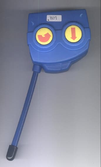
OX4829
Jun 09, 200327MHz Wireless R/C Toy - Transmitter
Equipment Class
DXX - Part 15 Low Power Communication Device Transmitter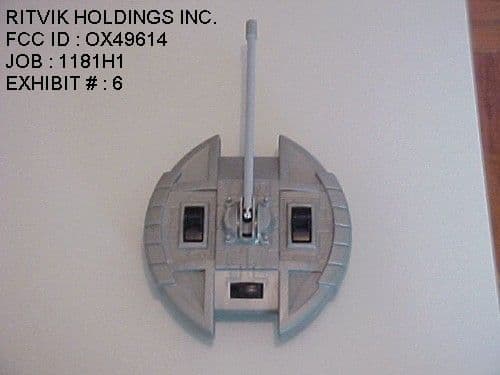
OX49614
Dec 16, 200127MHz R/C Toy Dual Frequency Transmitter
Equipment Class
DXX - Part 15 Low Power Communication Device Transmitter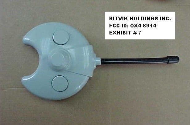
OX48914
Apr 23, 2000Toy R/C
Equipment Class
DXX - Part 15 Low Power Communication Device Transmitter