OXGAB86Mini Show Box
Willis Electric Co., Ltd.
Click to zoom
Application Details
- Equipment Class
- DTS - Digital Transmission System
- Date of Grant
- Apr 09, 2015
- Application Purpose
- Original Equipment
- Date of Application
- Apr 09, 2015
- Equipment Note
- Mini Show Box
- Frequency Range
- 2412.00000000 - 2462.00000000
- Company
- Willis Electric Co., Ltd.
- Country
- Taiwan
Documents & Files
Document Text
Text extracted from the exhibit documents filed with the FCC. Open a document above to read the original.
Users Manual
1 ATTACH YOUR RECEIPT HERE Serial Number _______________ Purchase Date _______________ SHOW BOX MINI 2 PACKAGE CONTENTS PART DESCRIPTION QUANTITY A Show box mini 1 B Ground stake 1 C Audio cable 1 3 PRODUCT FUNCTION The show box mini enables the user to plug in lights, trees and yard decorations, connect your favorite music, and select from 9 functions to create your very own light and sound show. Introduction of mini show box 1. There are 3 outlets behind the mini show box for plugging in. 2. Touch panel, manual operation: z Choose different light show mode. z LED display, indicate different light show mode. z Volume adjustment. 3. The mini show box has Wi-Fi function, you can control mini show box through smart mobile devices App. z Deliver the music on the smart mobile devices to the mini show box. The music will play on the mini show box. z Turn ON/OFF the mini show box. z Choose different light show mode. z Choose different timer (choose the working time of mini show box). z Control the power of 3 outlets individually as power output. 4 OPERATION INSTRUCTIONS The mini show box needs to be plugged into a power source. It can be plugged into a wall socket directly or into a power cord. Note: always use UL approved power cords with outdoor rating GFCI outlet, when plugging in your lights, trees and yard décor. Plug 3 different combinations of lights, trees, and decorations into the 3 outlets on the back of show box. Please make sure the power consumption (Watts) of the each combination is under the max Watts limitation. When the power supply is on, turn on the power switch on the back of show box. The LED display panel shows “- -” 1. Press the Function Button on mini show box panel. The LED display panel shows “00” The 3 different receptacles turn on one time sequentially, then all turn on. 2. There are 8 functions of programmed light show modes. Press the Function Button on show box panel to select. Function 1-7: LED Display panel shows “01-07” Function 8: Lights dance along with the melody of music. 3. Press the ON/OFF Button power off. 4. Line in mode: Deliver the music to the mini show box via the audio cable. The light show mode automatically changes to function 8 (LED display panel shows “08”) 5. During Line in mode, the Wi-Fi from smart mobile devices cannot be used to transmit music. 5 SAFETY INSTRUCTIONS Please read and understand this entire manual before attempting to assemble, operate or install the product. 1. When in the mode of light & sound show (Light of output plug dances along with music), the maximum output amperage of each plug is 2.5A. 2. When using remote control to control the power (using phone app), the output amperage of each output plug is 2.5A(maximum). 3. CAUTION – Risk of Fire. Not for permanent installation. Use only with a total of 10.2 Ampere maximum lighting products. Do not install or use this product for more than a 90-day period. 4. If using lighting products that are not marked with an ampere rating, connect no more than 140 screw-base lamps (C7 or C9) or 12 strings with midget (push-in) lamps to this cord set. 5. If using an Outdoor Seasonal - Use Cord Connected Wiring Device for an extended period of time (greater than 90 days) please consider hard wiring a permanent outdoor-use receptacle rated for year-round use in the area that power is needed. Please contact a licensed electrician for proper installation of permanent wiring. 6. SUITABLE FOR INDOOR/OUTDOOR USE – STORE INDOORS WHILE NOT IN USE. 7. CAUTION: PLUG INTO GROUND FAULT PROTECTED RECEPTACLE ONLY. 8. After completion of installation, the connector shall be maintained a minimum of 6 inches above ground. Before beginning assembly of product, make sure all parts are present. Compare parts with package contents list. If any part is missing or damaged, do not attempt to assemble, install or operate the product. Estimated Assembly Time: 20 minutes No tools required for assembly. ASSEMBLY INSTRUCTIONS 1. Assemble the ground stake. (Only if need to use the ground stake.) PREPARATION 1 6 2. Choose a location of installation in your yard. Insert the ground stake into ground stake jack of show box at the bottom of show box mini. Insert the ground stake with mini show box into the ground. Note: Plug the power cord of show box to the wall receptacle of the house to avoid damage from rain or water. Fn Button Function 1-10: - 01: Sequential - 02: Back and Forth - 03: Step up Flashing - 04: Paired Flashing - 05: Step on/ Step off - 06: Group Flashing - 07: Random Flashing - 08: Half and Half - 09: Steady On - 10: Music Synch 2 7 Smart Mobile Devices Operation Please remove the audio cable from Mini Show Box if using Wi-Fi operations. 1. Download application named “Show Box” App on your smart mobile devices. (iOS : App store/Android/HTC : Google play, play store) 2. Go to Set on device for Wi-Fi setting. Look for “Mini Show Box” and select it to get connected. (Fig. 1) 3. Start “Show Box ” App. (Fig. 2) 4. The opening screen of application “Show Box” is shown on Fig. 3. 5. Main Menu is shown on Fig. 4. Fig. 1 Fig. 2 Fig. 3 Fig. 4 POWER SWITCH This is to turn on/off the Mini Show Box. FUNCTIONS SELECTION 10 functions can be selected by sliding horizontally. The color of this icon changes after each pressing. 8 TIMER FUNCTION Power will stay on during the selected time is count down. Set the timer of Show Box for 1/2/4/8/12 hours. PLUG FUNCTION Switch of 3 plugs: Individually turn on/off these 3 plugs. MUSIC PLAYER FUNCTION For Android : 1. Music Selection 2. Player Functions (from left to right): z Random Play z Back z Play z Forward z Stop 3. Current Music Playing Position 9 MUSIC PLAYER OPERATION FOR IPHONE USER 1. Touch the music icon from the main menu. 2. Application will open your music playlist. 3. Select a song from the playlist. Once selected, swipe screen from bottom to top to open new screen as Fig. 3. 4. Select “AirPlay” in the new screen as Fig. 4. 5. On the next screen, select “Show Box”. …
Text truncated - open the document above for the full version.
Cover Letter(s)
FCC Confidentiality Request To the FCC andFCC TCB handling this application for certification Pursuant to 47 CFR Section 0.459(a) & (b), we, (the applicant / grantee) Company nameWillis Electric CO.,Ltd. AddresssNo.504-1,Chung-Hua Road, Sec.4, Hsin Chu,300, Taiwan CityHsin Chu Country request non-disclosureand confidential treatmentfor our certification under: Grantee CodeProduct Number FCC ID:OXGAB86 of the following materials submitted within this certification application: (please cross what is applicable, or add other documents) XOperational Description xBlock Diagrams xSchematics Diagrams Turn up produrce Bill of Materials Above materials contain secrets, proprietary and technical information, which would customarily be guarded from competitors under 47 CFR, section 0.457(d)(2). Disclosure or publication or any portion of this company confidential material to other parties could cause substantial competitive harm and provide unjustified benefits for competitors. We understand that pursuant to 47 CFR section 0.457(d)(1)(ii) disclosure of the applicant and all accompanying documentation will not be made before the date of the grant. Attestation: City and Country:Date:Name: (this must be a person) Function:Signature: (or official company stamp) Hsin Chu 2015 -03-09 Grace DaiSafety Engineer
External Photos
APPENDIX-PHOTOGRAPHS OF EUT CONSTRUCTIONAL DETAILS
ID Label/Location Info
Label and Label Location
Internal Photos
APPENDIX-PHOTOGRAPHS OF EUT CONSTRUCTIONAL DETAILS
RF Exposure Info
RF EXPOSURE TEST FCC ID: OXGAB86 Applied procedures / limit These devices are not exempted from compliance does not exceed the Commission’s RF exposure guidelines.Unless a device operates at substantially low power levels,with a low gain antenna(s),supporting information is generally needed to establish the various potential operating configurations and exposure conditions of a transmitter and its antenna(s) in order to determine compliance with the RF exposure guidelines. In order to demonstrate compliance with MPE requirement(see Section 2.1091),the following information is typically needed: Calculation that estimates the minimum separation distance(20 cm or more)between an antenna and persons required to satisfy power density limits defined for free space. Antenna installation and device operating instructions for installers(professional/unskilled users),and the parties responsible for ensuring compliance with the RF exposure requirement Any caution statements and/or warming labels that are necessary in order to comply with the exposure limits Any other RF exposure related issues that may affect MPE compliance. FCC 1.1310: The criteria listed in the following table shall be used to evaluate the environmental impact of human exposure to radio-frequency(RF) radiation as specified in 1.1307(b). (A) Limits for Occupational / Controlled Exposure Frequency Range (MHz) Electric Field Strength (E) (V/m) Magnetic Field Strength (H) (A/m) Power Density (S) (mW/ cm 2 ) Averaging Time |E| 2 ,|H| 2 or S (minutes) 0.3-3.0 614 1.63 (100)* 6 3.0-30 1842 / f 4.89 / f (900 / f)* 6 30-300 61.4 0.163 1.0 6 300-1500 F/300 6 1500-100,000 5 6 (B) Limits for General Population / Uncontrolled Exposure Frequency Range (MHz) Electric Field Strength (E) (V/m) Magnetic Field Strength (H) (A/m) Power Density (S) (mW/ cm 2 ) Averaging Time |E| 2 ,|H| 2 or S (minutes) 0.3-1.34 614 1.63 (100)* 30 1.34-30 824/f 2.19/f (180/f)* 30 30-300 27.5 0.073 0.2 30 300-1500 F/1500 30 1500-100,000 1.0 30 Note: f = frequency in MHz ; *Plane-wave equivalent power density MPE CALCULATION METHOD Calculation Method of RF Safety Distance: P :power input to the antenna in Mw EIRP :Equivalent(effective) isotropic radiated power. S :power density mW/ cm 2 G ;numeric gain of antenna relative to isotropic radiator R :distance to centre of radiation in cm FCC radio frequency exposure limits may be exceeded at distances closer than r cm from the antenna of this device EIRP=10 ( Antenna Gain+Peak Output Power/10) Note: 1. s=1.0 mW /cm 2 for limits for General Population/Uncontrolled Exposures. 2. The time averaged power over 30 minutes will be equaled Output Power. 3. The Power Density at a distance of 20cm calculated from the formula is far below the limit of 1MW/ cm 2 TEST RESULTS WIFI:2412-2462MHz NOTE: (For mobile or fixed location transmitters, the maximum power density is 1.0mW/cm 2 even if the calculation indicates that the power density would be larger) Min. operating distance between users and EUT: 20cm PK output power (AV) (dBm) Output power to antenna (mW) Antenna Gain (numeric) Power Density (S) (mW/ cm 2 ) Limit of Power Density (S) (mW/ cm 2 ) Result 14.32 27.04 1.641(2.15dbi)0.0088 1 Pass
Test Report
FCC RADIO TEST REPORT Prepared For Willis Electric CO., Ltd. Product Name: Mini Show Box Trade Name: Show Box Model Name : AB86 FCC ID: OXGAB86 Prepared By DongGuan Precise Testing Service Co.,Ltd. Building D, Baoding Technology Park, Guangming Road 2, Guangming Community, Dongcheng District, Dongguan, Guangdong, China Report No. PTS201503051 F Test Date: M a r. 09, 2015 ~ M a r. 18, 2015 Date of Report : M a r. 18, 2015 Page 2 of 54 Report No.: PTS201503051F TEST RESULT CERTIFICATION Applicant’s name ................. : Willis Electric CO.,Ltd. Address ................................. : No.504-1, Chung-Hua Road, Sec.4,Hsin Chu 300, Taiwan Manufacture's Name ............ : Kupoint(DongGuan)Electric Co.,Ltd Address ................................. : Huai De Village, HumenTown, Dong Guan, Guang Dong, China Product description Product name ............................ : Mini Show Box Model and/or type reference : AB86 Serial Model .............................. : N/A Standards ............................. : FCC Part15.247, IC RSS-210,Issue 8, December 2010 Test procedure .............................. ANSI C63.4-2014, RSS-Gen ISSUE 4 November 2014 Prepared by : Assistant Reviewer : Supervisor Approved & Authorized Signer : Jacky Ou / Manager Page 3 of 54 Report No.: PTS201503051F Table of Contents Page 1 . SUMMARY OF TEST RESULTS 5 1.1 TEST FACILITY 6 1.2 MEASUREMENT UNCERTAINTY 6 2 . GENERAL INFORMATION 7 2.1 GENERAL DESCRIPTION OF EUT 7 2.2 DESCRIPTION OF TEST MODES 9 2.3 BLOCK DIGRAM SHOWING THE CONFIGURATION OF SYSTEM TESTED 10 2.4 DESCRIPTION OF SUPPORT UNITS(CONDUCTED MODE) 11 2.5 EQUIPMENTS LIST FOR ALL TEST ITEMS 12 3 . EMC EMISSION TEST 14 3.1 CONDUCTED EMISSION MEASUREMENT 14 3.1.1 POWER LINE CONDUCTED EMISSION LIMITS 14 3.1.2 TEST PROCEDURE 15 3.1.3 DEVIATION FROM TEST STANDARD 15 3.1.4 TEST SETUP 15 3.1.5 EUT OPERATING CONDITIONS 15 3.1.6 TEST RESULTS 16 3.2 RADIATED EMISSION MEASUREMENT 18 3.2.1 RADIATED EMISSION LIMITS 18 3.2.2 TEST PROCEDURE 19 3.2.3 DEVIATION FROM TEST STANDARD 19 3.2.4 TEST SETUP 20 3.2.5 EUT OPERATING CONDITIONS 21 3.2.6 TEST RESULTS (BETWEEN 9KHZ – 30 MHZ) 22 3.2.7 TEST RESULTS (BETWEEN 30MHZ – 1GHZ) 23 3.3 BAND EDGE EMISSION (RADIATED): 25 4 . POWER SPECTRAL DENSITY TEST 26 4.1 APPLIED PROCEDURES / LIMIT 26 4.1.1 TEST PROCEDURE 26 4.1.2 DEVIATION FROM STANDARD 26 4.1.3 TEST SETUP 26 4.1.4 EUT OPERATION CONDITIONS 26 4.1.5 TEST RESULTS 27 5 . BANDWIDTH TEST 35 5.1 APPLIED PROCEDURES / LIMIT 35 5.1.1 TEST PROCEDURE 35 Page 4 of 54 Report No.: PTS201503051F Table of Contents Page 5.1.2 DEVIATION FROM STANDARD 35 5.1.3 TEST SETUP 35 5.1.4 EUT OPERATION CONDITIONS 35 5.1.5 TEST RESULTS 36 6 . PEAK OUTPUT POWER TEST 44 6.1 APPLIED PROCEDURES / LIMIT 44 6.1.1 TEST PROCEDURE 44 6.1.2 DEVIATION FROM STANDARD 44 6.1.3 TEST SETUP 44 6.1.4 EUT OPERATION CONDITIONS 44 6.1.5 TEST RESULTS 45 7 . 100 KHZ BANDWIDTH OF FREQUENCY BAND EDGE 46 7.1 DEVIATION FROM STANDARD 46 7.2 TEST SETUP 46 7.3 EUT OPERATION CONDITIONS 46 7.4 TEST RESULTS 47 8 . ANTENNA REQUIREMENT 52 8.1 STANDARD REQUIREMENT 52 8.2 EUT ANTENNA 52 8. EUT TEST PHOTO 53 APPENDIX-PHOTOGRAPHS OF EUT CONSTRUCTIONAL DETAILS Page 5 of 54 Report No.: PTS201503051F 1. SUMMARY OF TEST RESULTS Test procedures according to the technical standards: FCC Part15 (15.247) , Subpart C KDB558074 D01 DTS Meas Guidance v03r02 Standard Section Test Item Judgment Remark 15.207 Conducted Emission PASS 15.247 (a)(2) 6dB Bandwidth PASS 15.247 (b) Peak Output Power PASS 15.247 (c) Radiated Spurious Emission PASS 15.247 (d) Power Spectral Density PASS 15.205 Band Edge Emission PASS 15.203 Antenna Requirement PASS NOTE: (1)” N/A” denotes test is not applicable in this Test Report Page 6 of 54 Report No.: PTS201503051F 1.1 TEST FACILITY Dongguan Dongdian Testing Service Co., Ltd Add.: No. 17, Zongbu Road 2, Songshan Lake Sci&Tech, Industry Park, Dongguan City, Guangdong Province, China, 523808 FCC Registration No.: 270092; IC Registration No.: 10288A-1 1.2 MEASUREMENT UNCERTAINTY The reported uncertainty of measurement y ± U,where expended uncertainty U is based on a standard uncertainty multiplied by a coverage factor of k=2,providing a level of confidence of approximately 95 %. No. Item Uncertainty 1 Conducted Emission Test ±1.38dB 2 RF power,conducted ±0.16dB 3 Spurious emissions,conducted ±0.21dB 4 All emissions,radiated(<1G) ±4.68dB 5 All emissions,radiated(>1G) ±4.89dB 6 Temperature ±0.5°C 7 Humidity ±2% Page 7 of 54 Report No.: PTS201503051F 2. GENERAL INFORMATION 2.1 GENERAL DESCRIPTION OF EUT Equipment Mini Show Box Trade Name Show Box Model Name AB86 Serial Model N/A Model Difference N/A Product Description The EUT is a Mini Show Box Operation Frequency: 802.11b/g/n(20MHz):2412~2462 MHz 802.11n(40MHz):2422~2452 Modulation Type: CCK/OFDM/DBPSK/DAPSK Bit Rate of Transmitter 802.11b:11/5.5/2/1 Mbps 802.11g:54/48/36/24/18/12/9/6Mbps 802.11n(20/40MHz):150/144.44/130/1 17/115.56/104/86.67/78/52/6.5Mbps Number Of Channel 802.11b/g/n20MHz:11CH 802.11n40MHz:7CH Antenna Designation: Please see Note 3. Output Power(Conducted, PK): 802.11b: 17.64 dBm (Max.) 802.11g: 14.77 dBm (Max.) 802.11n(20M) : 14.89dBm (Max.) 802.11n (40M): 13.79 dBm (Max.) Antenna Gain (dBi) 2.15dbi Based on the application, features, or specification exhibited in User's Manual, the EUT is considered as an ITE/Computing Device. More details of EUT technical specification, please refer to the User's Manual. Channel List Please refer to the Note 2. Ratings AC 120V Adapter N/A Battery N/A Hardware version V2 Software version F_mini show box V1 Connecting I/O Port(s) Please refer to the User's Manual Note: Page 8 of 54 Report No.: PTS201503051F 1. For a more detailed features description, please refer to the manufacturer’s specifications or the User's Manual. 2. Channel List for 802.11b/g/n(20) Channel Frequency (MHz) Channel Frequency (MHz) Channel Frequency (MHz) Channel Frequency (MHz) 01 2412 04 2427 07 2442 10 2457 02 2417 05 2432 08 2447 11 2462 03 2422 06 2437…
Text truncated - open the document above for the full version.
Test Setup Photos
APPENDIX-PHOTOGRAPHS OF EUT CONSTRUCTIONAL DETAILS
Contact Information
Applicant
Grace Dai(Safety Engineer)
Test Firm
Dongguan Dongdian Testing Service Co.,LtdJamy Yu
[email protected]086-0769-22891499
Technical Specifications
| # | Rule Parts | Frequency Range | Power Output |
|---|---|---|---|
| 1 | 15C | 2.41 GHz - 2.46 GHz | 58.00 mW |
Other Applications from Willis Electric Co., Ltd.
OXGSH03
Mar 15, 2021Flood lights
Equipment Class
DSC - Part 15 Security/Remote Control Transmitter
OXGSL90V2
May 06, 2020300L Ultimate light string
Equipment Class
DTS - Digital Transmission System
OXGAL28TX
Mar 29, 2020Remote control
Equipment Class
DSC - Part 15 Security/Remote Control Transmitter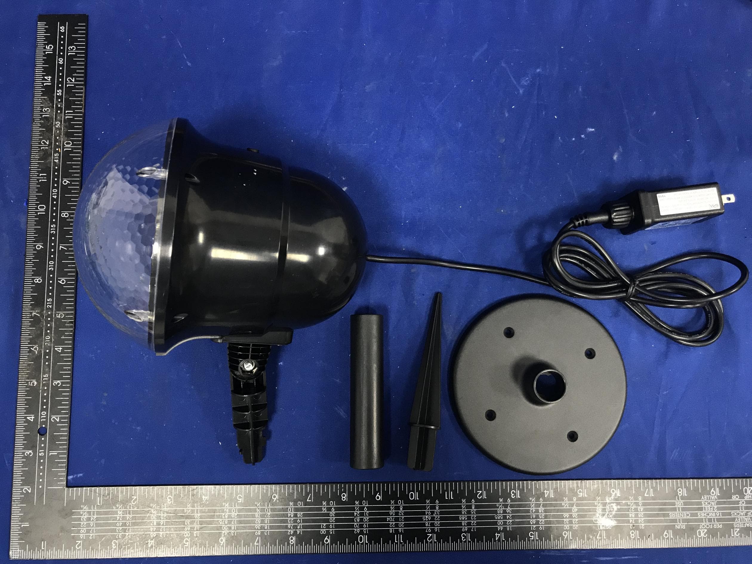
OXGAL28
Mar 25, 2020Super Projector
Equipment Class
JAB - Part 15 Class B Digital Device
OXGZW112
Jun 10, 2015Motion Sensor
Equipment Class
DXT - Part 15 Low Power Transceiver, Rx Verified