OXGZW31Smart Dimmer
Willis Electric Co., Ltd.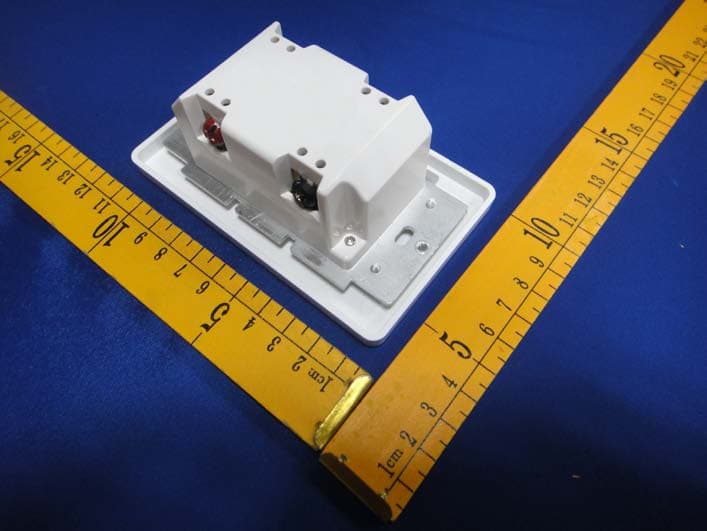
Click to zoom
Application Details
- Equipment Class
- DXX - Part 15 Low Power Communication Device Transmitter
- Date of Grant
- Apr 16, 2015
- Application Purpose
- Original Equipment
- Date of Application
- Apr 16, 2015
- Equipment Note
- Smart Dimmer
- Frequency Range
- 908.42000000 - 908.42000000
- Company
- Willis Electric Co., Ltd.
- Country
- Taiwan
Documents & Files
Document Text
Text extracted from the exhibit documents filed with the FCC. Open a document above to read the original.
Users Manual
FCC/IC ZW31 Smart Dimmer Manual Federal Communications Commission (FCC) Statement FCC Caution: Any changes or modifications not expressly approved by the party responsible for compliance could void the user ’s authority to operate this equipment. This device complies with Part 15 of the FCC Rules. Operation is subject to the following two conditions: (1) This device may not cause harmful interference, and (2) this device must accept any interference received, including interference that may cause undesired operation. NOTE: This equipment has been tested and found to comply with the limits for a Class B digital device, pursuant to Part 15 of the FCC Rules. These limits are designed to provide reasonable protection against harmful interference in a residential installation. This equipment generates, uses and can radiate radio frequency energy and, if not installed and used in accordance with the instructions, may cause harmful interference to radio communications. However, there is no guarantee that interference will not occur in a particular installation. If this equipment does cause harmful interference to radio or television reception, which can be determined by turning the equipment off and on, the user is encouraged to try to correct the interference by one or more of the followingmeasures: -- Reorient or relocate the receiving antenna. -- Increase the separation between the equipment and receiver. -- Connect the equipment into an outlet on a circuit different from that to which the receiver is connected. -- Consult the dealer or an experienced radio/TV technician for help. IC Caution: This device complies with Industry Canada licence-exempt RSS standard(s). Operation is subject to the following two conditions: (1) this device may not cause interference, and (2) this device must accept any interference, including interference that may cause undesired operation of the device. In-wall smart dimmer DECLARATION DE CONFORMITE D'INDUSTRIE CANADA Le présent appareil est conforme aux CNR d’Industrie Canada applicables aux appareils radio exempts de licence. L’exploitation est autorisée aux deux conditions suivantes : (1) l’appareil ne doit pas produire de brouillage; (2) l’utilisateur de l’appareil doit accepter tout brouillage radioélectrique subi, même. si le brouillage est susceptible d’en compromettre le fonctionnement.. WARRANTY Show Home Products warrants this product to be free from manufacturing defects for a period of two years from the original date of consumer purchase. This warranty is limited to the repair or replacement of this product only and does not extend to consequential or incidental damage to other products that may be used with this product. This warranty is in lieu of all other warranties, expressed or implied. Some states do not allow limitations on how long an implied warranty lasts or permit the exclusion or limitation of incidental or consequential damage, so the above limitations may not apply to you. This warranty gives you specific rights, and you may also have other rights which vary from state to state. if the unit should prove defective within the warranty period. SPECIFICATIONS WARNING Model:ZW31 Power: 120 VAC, 60 Hz. Signal (Frequency): 908.42 MHZ. Maximum Loads: 500W, 2-gang 400W or 3-gang 300W incandescent, 150W CFL/LED Range: Up to 100 feet line of sight between the Wireless Controller and the closest Z-Wave receiver module. Operating Temperature Range: 32-104° F (0-40° C) For indoor use only. Specifications subject to change without notice due to continuing product improvement IMPORTANT! The fixture controlled by the Z-Wave In-wall Smart Dimmer must not exceed 600 watts (Incandescent); 150W dimmable CFL/LED. The Dimmer is designed only for use with permanently installed fixtures. Website:www.ishowlights.com RISK OF FIRE RISK OF ELECTRICAL SHOCK RISK OF BURNS CONTROLLING APPLIANCES: EXERCISE EXTREME CAUTION WHEN USING Z-WAVE DEVICES TO CONTROL APPLIANCES. OPERATION OF THE Z-WAVE DEVICE MAY BE IN A DIFFERENT ROOM THAN THE CONTROLLED APPLIANCE, ALSO AN UNINTENTIONAL ACTIVATION MAY OCCUR IF THE WRONG BUTTON ON THE REMOTE IS PRESSED. Z-WAVE DEVICES MAY AUTOMATICALLY BE POWERED ON DUE TO TIMED EVENT PROGRAMMING. DEPENDING UPON THE APPLI- ANCE, THESE UNATTENDED OR UNINTENTIONAL OP- ERATIONS COULD POSSIBLY RESULT IN A HAZARDOUS CONDITION. FOR THESE REASONS, WE RECOMMEND DO NOT RETURN THIS PRODUCT TO THE STORE THE FOLLOWING: DO NOT USE Z-WAVE DEVICES TO CONTROL ELECTRIC HEATERS OR ANY OTHER APPLIANCES WHICH MAY PRES- ENT A HAZARDOUS CONDITION DUE TO UNATTENDED OR UNINTENTIONAL OR AUTOMATIC POWER ON CONTROL. Getting To Know Your New Z-Wave Device Turn ON/OFF and adjust dim levels manually or remotely via the Z-Wave controller • Can be Included in multiple Groups and Scenes • May be used in single pole installation or with up to two GE Add-on switches in 3-way or 4-way wiring configurations • Compatible with all incandescent and most dimmable CFL/LED bulbs • Interchangeable Paddle switch — White & light almond paddle in package • Uses a standard, decorative-size wall plate for single gang installations ( wall plate not included) • Blue LED indicates switch location in a dark room • Z-Wave Certified for simple pairing and integrated home automation • Screw Terminal Installation — requires wiring connections for Line (Hot), Load, Neutral, and Ground. Traveler wire required for 3-way or 4-way installation A. Top Rocker — (Press &release to turn Dimmer on,press & hold increases brightness) B. Bottom Rocker — (Press& release to turn Dimmer off,press & hold to dim) C. Ground (Green/Bare) D. Load (Black) E. Line (Black) F. Traveler (Red/Other) G.Neutral (White) Single, Dual And Triple Gang Boxes When installing the In -wall Smart Dimmer in multiple gang boxes it may be necessary to break off one or both sides of the scored tabs on the front yoke.This will affect the electrical rating of the switch (see specifications for details) WARNING — SHOCK HAZARD Turn OFF the powe…
Text truncated - open the document above for the full version.
Cover Letter(s)
FCC Confidentiality Request To the FCC and FCC TCB handling this application for certification Pursuant to 47 CFR Section 0.459(a) & (b), we, (the applicant / grantee) Company name Willis Electric CO.,Ltd. Addresss No.504-1,Chung-Hua Road, Sec.4, Hsin Chu,300 Taiwan City Hsin Chu Country request non-disclosure and confidential treatment for our certification under: Grantee Code Product Number FCC ID: OXG ZW31 of the following materials submitted within this certification application: (please cross what is applicable, or add other documents) X Operational Description x Block Diagrams x Schematics Diagrams Turn up produrce Bill of Materials Above materials contain secrets, proprietary and technical information, which would customarily be guarded from competitors under 47 CFR, section 0.457(d)(2). Disclosure or publication or any portion of this company confidential material to other parties could cause substantial competitive harm and provide unjustified benefits for competitors. We understand that pursuant to 47 CFR section 0.457(d)(1)(ii) disclosure of the applicant and all accompanying documentation will not be made before the date of the grant. Attestation: City and Country: Date: Name: (this must be a person) Function: Signature: (or official company stamp) Hsin Chu 2015 -03-16 Grace Dai Safety Engineer
External Photos
APPENDIX-PHOTOGRAPHS OF EUT CONSTRUCTIONAL DETAILS
ID Label/Location Info
Label And Label Location
Internal Photos
APPENDIX-PHOTOGRAPHS OF EUT CONSTRUCTIONAL DETAILS Antenna
Test Report
FCC RADIO TEST REPORT FCC ID: OXGZW31 IC: 10460A-ZW31 Product Name: Smart Dimmer Trademark: Show Home Model Number: ZW31 Prepared For : Willis Electric CO.,Ltd. Address : No.504-1,Chung-Hua Road, Sec.4, Hsin Chu,300 Taiwan Prepared By : DongGuan Precise Testing Service Co.,Ltd. Address : Building D, Baoding Technology Park, Guangming Road 2, Guangming Community, Dongcheng District, Dongguan, Guangdong, China Test Date: Mar. 11 - Mar. 25, 2015 Date of Report : Mar. 25, 2015 Report No.: PTS1503058015F Page 2 of 27 Report No.: PTS1503058015F VERIFICATION OF COMPLIANCE Applicant: Willis Electric CO.,Ltd. Address No.504-1,Chung-Hua Road, Sec.4, Hsin Chu,300 Taiwan Manufacturer Name: Kupoint(DongGuan)Electric Co.,Ltd Address: Huai De Village, HumenTown, Dong Guan, Guang Dong, China Product Description: Smart Dimmer Brand Name: Show Home Model Name: ZW31 Model difference: N/A Test procedure ANSI C63.4-2014, CISPR 16-1-4:2010, RSS-Gen Issue 4,2014 Standards FCC PART15.249, RSS-210 Issue 8,Dec 2010 Prepared by : Assistant Reviewer : Supervisor Approved & Authorized Signer : Page 3 of 27 Report No.: PTS1503058015F Table of Contents Page 1 . SUMMARY OF TEST RESULTS 4 1.1 TEST FACILITY 5 1.2 MEASUREMENT UNCERTAINTY 5 2 . GENERAL INFORMATION 6 2.1 GENERAL DESCRIPTION OF EUT 6 2.2 DESCRIPTION OF TEST MODES 7 2.3 BLOCK DIGRAM SHOWING THE CONFIGURATION OF SYSTEM TESTED 8 2.4 DESCRIPTION OF SUPPORT UNITS(CONDUCTED MODE) 9 2.5 EQUIPMENTS LIST FOR ALL TEST ITEMS 10 3 . TEST RESULT 11 3.1 ANTENNA REQUIREMENT 11 3.1.1 STANDARD REQUIREMENT 11 3.1.2 EUT ANTENNA 11 3.2 CONDUCTED EMISSION MEASUREMENT 12 3.2.1 POWER LINE CONDUCTED EMISSION LIMITS 12 3.2.2 TEST PROCEDURE 13 3.2.3 DEVIATION FROM TEST STANDARD 13 3.2.4 TEST SETUP 13 3.2.5 TEST RESULT 14 3.3 RADIATED EMISSION MEASUREMENT 16 3.3.1 RADIATED EMISSION LIMITS 16 3.3.2 TEST PROCEDURE 17 3.3.3 DEVIATION FROM TEST STANDARD 17 3.3.4 TEST SETUP 18 3.3.5 TEST RESULTS (BLOW 30MHZ) 20 3.3.6 TEST RESULTS (BETWEEN 30 – 1000 MHZ) 21 3.3.7 TEST RESULTS (ABOVE 1000 MHZ) 24 4 . 20DB BANDWIDTH TEST 26 4.1 TEST PROCEDURE 26 4.2 DEVIATION FROM STANDARD 26 4.3 TEST SETUP 26 4.4 TEST RESULTS 27 APPENDIX-PHOTOGRAPHS OF EUT CONSTRUCTIONAL DETAILS Page 4 of 27 Report No.: PTS1503058015F 1. SUMMARY OF TEST RESULTS Test procedures according to the technical standards: FCC Part15, Subpart C (15.249) RSS-Gen Issue 4 & RSS-210 Issue 8 Standard Section Test Item Judgment Remark 15.207& RSS-Gen issue 4,8.8 Conducted Emission Pass 15.203 Antenna Requirement Pass 15.249& A8.5 Radiated Spurious Emission Pass 15.249& A8.1 20 DB Bandwidth Pass 15.205& A8.5 Band Edge Emission Pass Page 5 of 27 Report No.: PTS1503058015F 1.1 TEST FACILITY Dongguan Dongdian Testing Service Co., Ltd Add.: No. 17, Zongbu Road 2, Songshan Lake Sci&Tech, Industry Park, Dongguan City, Guangdong Province, China, 523808 FCC Registration No.: 270092; IC Registration No.: 10288A-1 1.2 MEASUREMENT UNCERTAINTY The reported uncertainty of measurement y ± U,where expended uncertainty U is based on a standard uncertainty multiplied by a coverage factor of k=2,providing a level of confidence of approximately 95 %。 No. Item Uncertainty 1 Conducted Emission Test ±1.38dB 2 RF power,conducted ±0.16dB 3 Spurious emissions,conducted ±0.21dB 4 All emissions,radiated(<1G) ±4.68dB 5 All emissions,radiated(>1G) ±4.89dB 6 Temperature ±0.5°C 7 Humidity ±2% Page 6 of 27 Report No.: PTS1503058015F 2. GENERAL INFORMATION 2.1 GENERAL DESCRIPTION OF EUT Equipment Smart Dimmer Trade Name Show Home Model Name ZW31 Serial Model N/A Model Difference N/A Product Description The EUT is a Smart Dimmer Operation Frequency: 908.42MHz Modulation Type: FSK Channel number 1 channel Antenna Designation: Wire antenna Antenna Gain(Peak) -2.1dBi Transmit Peak Power 85.21 dBuV/m Based on the application, features, or specification exhibited in User's Manual, the EUT is considered as an ITE/Computing Device. More details of EUT technical specification, please refer to the User's Manual. Power Supply AC 120V,60Hz HVIN ZW31 FVIN F_smart dimmer V1 Note: 1. For a more detailed features description, please refer to the manufacturer’s specifications or the User's Manual. Page 7 of 27 Report No.: PTS1503058015F 2.2 DESCRIPTION OF TEST MODES To investigate the maximum EMI emission characteristics generates from EUT, the test system was pre-scanning tested base on the consideration of following EUT operation mode or test configuration mode which possible have effect on EMI emission level. Each of these EUT operation mode(s) or test configuration mode(s) mentioned above was evaluated respectively. Pretest Mode Description Mode 1 TX For Conducted Emission Final Test Mode Description Mode 1 TX For Radiated Emission Final Test Mode Description Mode 1 TX Note: For the TX mode, the EUT is configured as the continuously transmitting mode. Page 8 of 27 Report No.: PTS1503058015F 2.3 BLOCK DIGRAM SHOWING THE CONFIGURATION OF SYSTEM TESTED E-1 EUT AC Page 9 of 27 Report No.: PTS1503058015F 2.4 DESCRIPTION OF SUPPORT UNITS(CONDUCTED MODE) The EUT has been tested as an independent unit together with other necessary accessories or support units. The following support units or accessories were used to form a representative test configuration during the tests. Item Equipment Mfr/Brand Model/Type No. Series No. Note E-1 Smart Dimmer Show Home ZW31 N/A EUT Item Shielded Type Ferrite Core Length Note Note: (1) The support equipment was authorized by Declaration of Confirmation. (2) For detachable type I/O cable should be specified the length in cm in『Length』column. Page 10 of 27 Report No.: PTS1503058015F 2.5 EQUIPMENTS LIST FOR ALL TEST ITEMS Radiation Test equipment Item Kind of Equipment Manufacturer Type No. Serial No. Last calibration Calibrated until 1 E MI Te st Receiver R&S ESU8 100316 2014/10/25 2015/10/24 2 Double Ridged Horn Antenna (0.8GHz-18GHz ) R&S HF907 100276 2014/11/01 2015/10/31 3 Log-periodic Dipole Antenna (30MHz-1GHz) R&S HL223 100435 2014/11/01 2015/10/3 1 4 Tr…
Text truncated - open the document above for the full version.
Test Setup Photos
APPENDIX-PHOTOGRAPHS OF EUT CONSTRUCTIONAL DETAILS
Contact Information
Applicant
Grace Dai(Safety Engineer)
Test Firm
Dongguan Dongdian Testing Service Co.,LtdJamy Yu
[email protected]086-0769-22891499
Technical Specifications
| # | Rule Parts | Frequency Range | Power Output |
|---|---|---|---|
| 1 | 15C | 908.42 MHz - 908.42 MHz | - |
Other Applications from Willis Electric Co., Ltd.
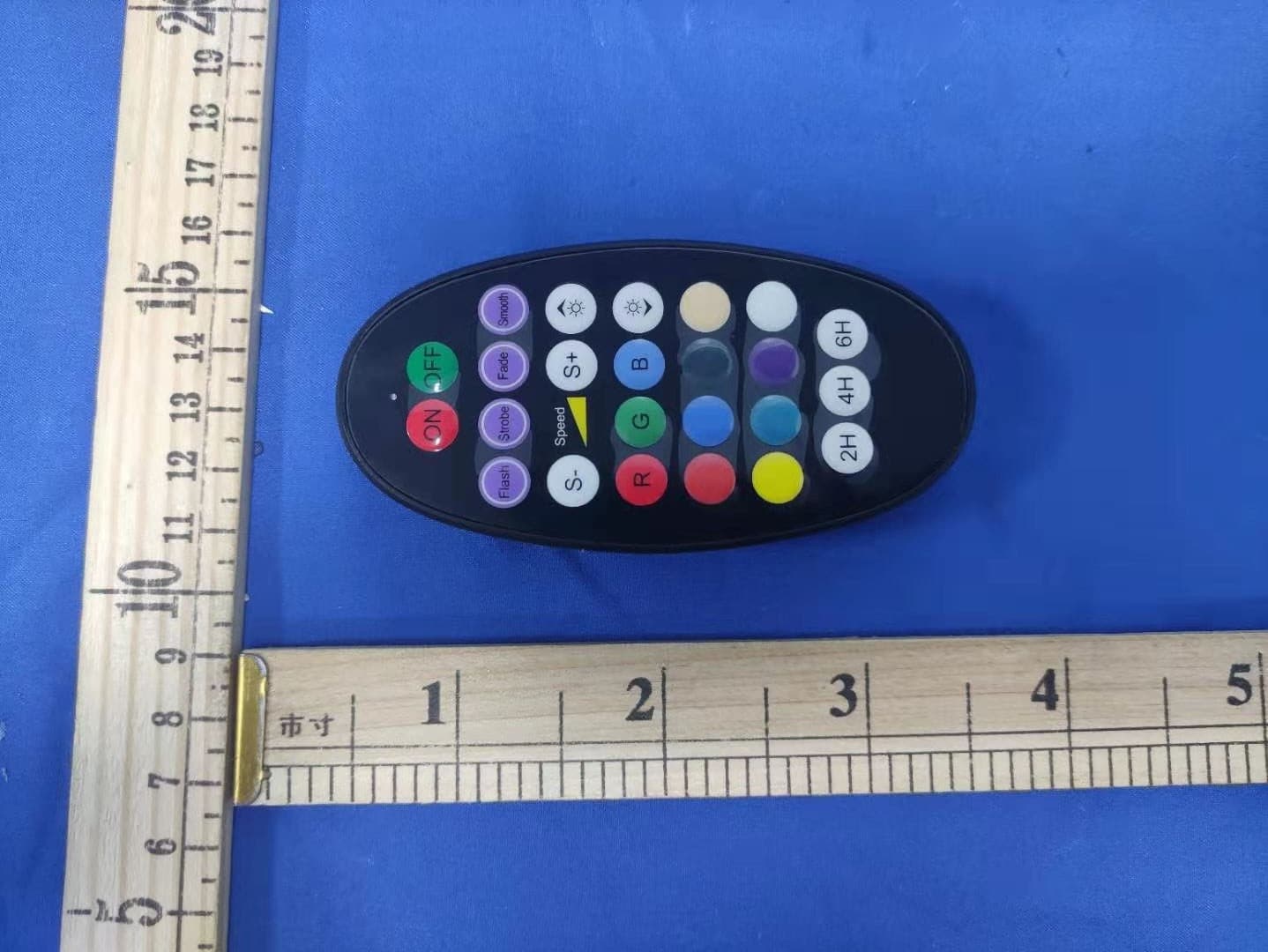
OXGSH03
Mar 15, 2021Flood lights
Equipment Class
DSC - Part 15 Security/Remote Control Transmitter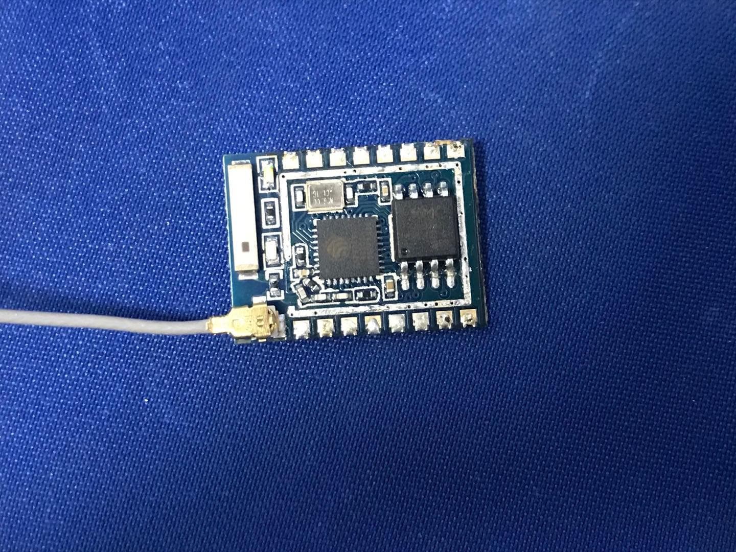
OXGSL90V2
May 06, 2020300L Ultimate light string
Equipment Class
DTS - Digital Transmission System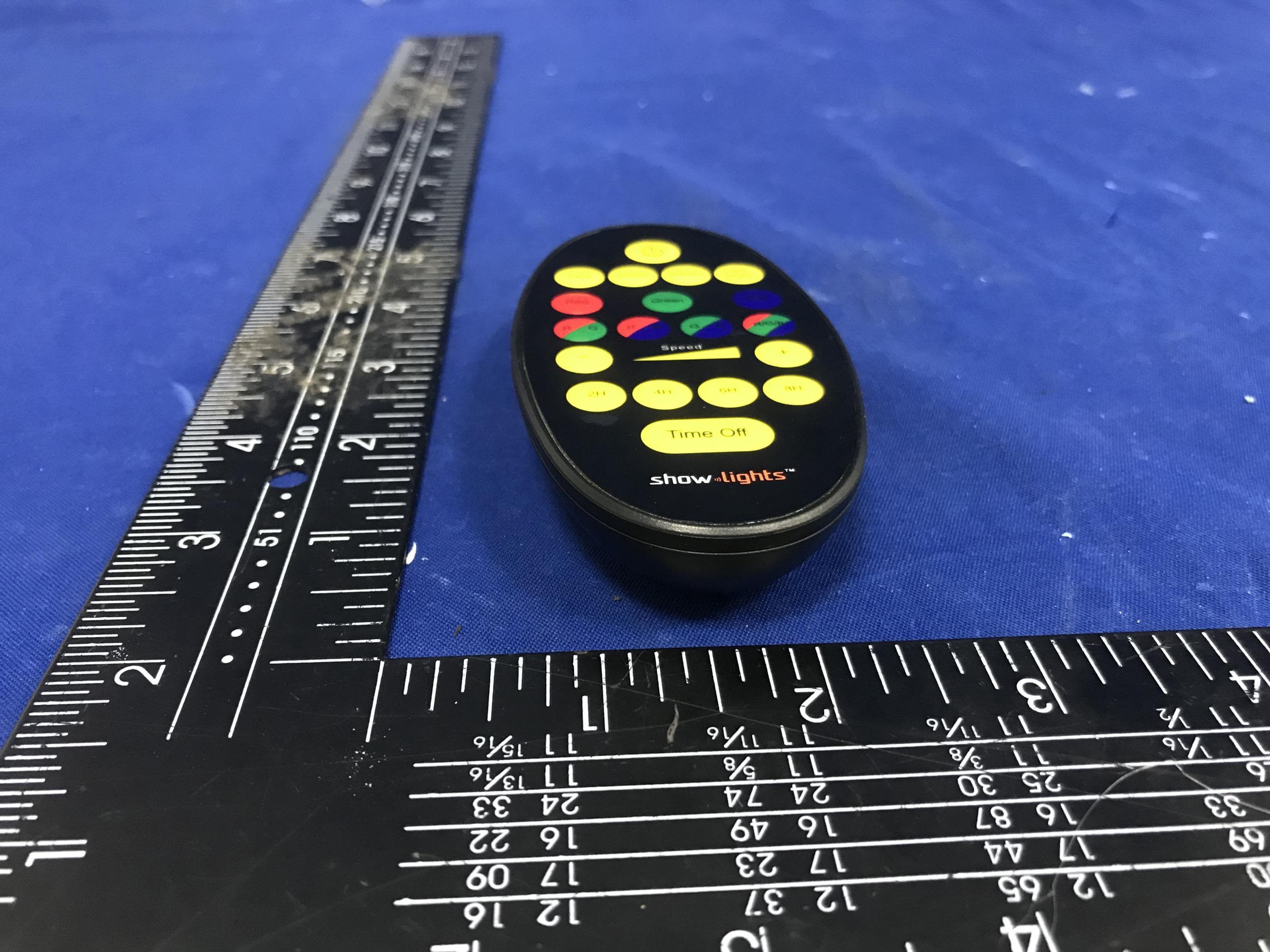
OXGAL28TX
Mar 29, 2020Remote control
Equipment Class
DSC - Part 15 Security/Remote Control Transmitter
OXGAL28
Mar 25, 2020Super Projector
Equipment Class
JAB - Part 15 Class B Digital Device
OXGZW112
Jun 10, 2015Motion Sensor
Equipment Class
DXT - Part 15 Low Power Transceiver, Rx Verified