OXGZW36Z-wave Smart Plug
Willis Electric Co., Ltd.
Click to zoom
Application Details
- Equipment Class
- DSR - Part 15 Remote Control/Security Device Transceiver
- Date of Grant
- Jun 19, 2014
- Application Purpose
- Original Equipment
- Date of Application
- Jun 19, 2014
- Equipment Note
- Z-wave Smart Plug
- Frequency Range
- 908.82000000 - 908.82000000
- Company
- Willis Electric Co., Ltd.
- Country
- Taiwan
Documents & Files
Document Text
Text extracted from the exhibit documents filed with the FCC. Open a document above to read the original.
Users Manual
User manual ZW36 Z-wave Smart Plug Willis’s family of Z-Wave credited wireless lighting controls (switches, dimmers, outlets and plug-in modules) brings a new level of intelligent wireless capability to commercial and residential environments. The Z-Wave wireless protocol is an international wireless standard for remote home automation, security and other applications. Embedded in each device, the Z-Wave smart chip enables two-way RF communication among hundreds of Z-Wave enabled devices, allowing products and services from multiple manufacturers to work seamlessly. Willis Z-Wave products are easy to install, and allow dealers to create an integrated wireless network with nearly limitless expansion and interoperability with security and health monitoring systems, energy management, home entertainment, appliances, and more. This product supports 40Kbps data transmission. This product can also be used for network support in systems that stream metadata. An example might include transmission of information from audio devices such as song title, artist, and album information to various displays around the home. As part of a Z-Wave network, the ZW36 will act as a wireless repeater to insure that commands intended for another device in the network are received. This is useful when the device would otherwise be out of the radio range of the wireless controller. INSTALLATION Plug this Appliance Module into the wall outlet near the load to be controlled, and plug the load into the Appliance Module. Make sure the load to be controlled is 10 amps or less. INCLUDING ZW36 TO THE NETWORK STEP 1. Prepare the Controller to include a unit to the network, by adding it to a group (method of adding a node to the network). Refer to controller instructions. STEP 2. The ZW36 must be in its permanently installed location. Tap the button on the ZW36 once. STEP 3. You should see an indication on your Controller that the “DEVICE WAS INCLUDED” in the network. NOTE: If you have trouble adding the ZW36 to a group it may be that the Home ID and Node ID were not cleared from it after testing. You must fi rst “RESET UNIT” with your controller to remove it from the network. Although adding it to a group includes it in the network, removing it from a group does not remove it from the network. If removed from a group, it functions only as a repeater BASIC OPERATION Button (Local Control) The button on the ZW36 allows the user to: • Turn the attached load on or off. • Include or exclude the module from the Z-Wave system. When a controller prompts you to “Send Node ID” or to “Press Button on Unit”, quickly tap the button once to satisfy those instructions. Tapping button toggles the load attached ON or OFF. Remote Control The ZW36 will respond to BASIC and BINARY commands that are part of the Z-Wave system. Refer to your controller’s instructions as to whether your controller can transmit those commands. All On/All Off The ZW36 supports the ALL ON/ALL OFF commands. The ZW36 can be set to respond to ALL ON and ALL OFF commands 4 different ways. Refer to your controller for information on how to set the ZW36 to operate in the manner you desire. Some controllers may be only able to set certain settings of ALL ON/ALL OFF response. The 4 different ways the ZW36 can be set up to respond to ALL ON and ALL OFF commands are: • ZW36 will not respond to ALL ON or the ALL OFF command. • ZW36 will respond to ALL OFF command but will not respond to ALL ON command. • ZW36 will respond to ALL ON command but will not respond to ALL OFF command. • ZW36 will respond to ALL ON and the ALL OFF command. Manufacturer Specifi c The ZW36 supports the Manufacturer Specifi c command. The ZW36 can return Manufacturer Specifi c information about itself. Refer to your Controller’s instructions on how to get this information from the ZW36 . SUC Support There must be a Static Update Controller in your Z-Wave system for this feature to work. The Static Controller can act as a gateway in the system, since other nodes always know its position (not moved after addition to the network. The “always listening” advantage of the Static Controller is that other nodes can transmit information frames to it whenever needed. You can assign an “SUC Route” to the ZW36 . Refer to your controller’s instructions on how to do this (if it supports it). Assigning an SUC Route to the ZW36 allows it to request an update of the Z-Wave devices that are between it and the Z-Wave device to which it was trying to transmit. The ZW36 will only request an update when a transmission fails. Confi guration The ZW36 supports the Confi guration command. The ZW36 can be confi gured to operate slightly differently that it works when you fi rst install it. Using the confi guration command you can confi gure the following (if your controller supports it) Set this parameter to 1 for normal ON/OFF operation. Set this parameter to 0 to enable fl ash mode which operates as follows: • With Parameter 104 value set to 0, relay is closed and ZW36 defaults to ON (relay closed) • Whenever the ZW36 receives a Z-Wave ON command, the ZW36 will begin cycling its output relay on and off approximately once per second (1/2 second Off, 1/2 second On) for 20 seconds. • If at any time during that 20 seconds, the ZW36 receives a Z-Wave OFF command, the ZW36 will stop cycling its output relay and default to ON. • At any time during that 20 seconds, if the ZW36 receives a Z-Wave ON command, the ZW36 will add an additional 20 seconds on/off cycling of its output relay. At the end of the 20 seconds, the ZW36 will again default to ON (relay closed). • At any other time, if the ZW36 receives an OFF command, it will have no effect and the ZW36 remains ON. INTEROPERABILITY WITH Z-WAVE™ DEVICES A Z-Wave™ network can integrate devices of various classes, and these devices can be made by different manufacturers. The ZW36 can be incorporated into existing Z-Wave™networks. The button on the face of the ZW36 can be used to carry o…
Text truncated - open the document above for the full version.
Cover Letter(s)
FCC Confidentiality Request To the FCC and FCC TCB handling this application for certification Pursuant to 47 CFR Section 0.459(a) & (b), we, (the applicant / grantee) Company name Willis Electric CO., Ltd. Addresss No.504-1, Chung-Hua Road, Sec.4 Hsin Chu, 300 Taiwan City 300 Taiwan Country request non-disclosure and confidential treatment for our certification under: Grantee Code Product Number FCC ID: OXG ZW36 of the following materials submitted within this certification application: (please cross what is applicable, or add other documents) x Operational Description x Block Diagrams x Schematics Diagrams Turn up produrce Bill of Materials Above materials contain secrets, proprietary and technical information, which would customarily be guarded from competitors under 47 CFR, section 0.457(d)(2). Disclosure or publication or any portion of this company confidential material to other parties could cause substantial competitive harm and provide unjustified benefits for competitors. We understand that pursuant to 47 CFR section 0.457(d)(1)(ii) disclosure of the applicant and all accompanying documentation will not be made before the date of the grant. Attestation: City and Country: Date: Name: (this must be a person) Function: Signature: (or official company stamp) Taiwan, China 2014 -06-03 Grace Dai Safety Engineer
External Photos
APPENDIX-PHOTOGRAPHS OF EUT CONSTRUCTIONAL DETAILS Photo 1 Photo 2 Photo 3 Photo 4 Photo 5
ID Label/Location Info
FCC ID LABELING AND LOCATION FCC ID Label Z-wave Smart Plug Model NO.: ZW36 Input Rating: AC 120V/60Hz FCC ID: OXGZW36 Willis Electric CO., Ltd.. Made in China This device complies with part 15 of the FCC Rules. Operation is subject to the following two conditions: (1)This device may not cause harmful interference, and (2) this device must accept any interference received, including interference that may cause undesired operation. FCC ID Label Location The label shown shall be permanently affixed at a conspicuous location on the device and be readily visible to the user at the time purchase (Labeling requirements per 2.925)
Internal Photos
Photo 6 Photo 7 Photo 8 Photo 9 ANT Photo 10 Photo 11 Photo 12 Photo 13
Test Report
FCC RADIO TEST REPORT FCC ID: OXGZW36 Product: Z-wave Smart Plug Trade Name: Show Home Model Name: ZW36 Serial Model: ZW37, ZW39 Prepared for Willis Electric CO., Ltd. No.504-1,Chung-Hua Road,Sec.4 Hsin Chu,300 Taiwan Prepared by DongGuan Precise Testing Service Co.,Ltd. Room 203-204, 2F, Xinye Building, No.67 Shijing, Guanzhang Road, Dongguan, China Page 2 of 28 Report No.: PT1401102005E ` TEST RESULT CERTIFICATION Applicant’s name................. : Willis Electric CO., Ltd. Address ................................. : No.504-1,Chung-Hua Road,Sec.4 Hsin Chu,300 Taiwan Manufacture's Name............ : Willis Electric CO., Ltd. Address ................................. : No.504-1,Chung-Hua Road,Sec.4 Hsin Chu,300 Taiwan Product description Product name ........................... : Z-wave Smart Plug Model and/or type reference : ZW36 Rating(s) ................................ : AC 120V/60Hz Standards............................. : FCC Part15.231 Test procedure .............................. ANSI C63.4-2003 This device described above has been tested by PTS, and the test results show that the equipment under test (EUT) is in compliance with the FCC requirements. And it is applicable only to the tested sample identified in the report. This report shall not be reproduced except in full, without the written approval of PTS, this document may be altered or revised by PTS, personal only, and shall be noted in the revision of the document. Date of Test............................................: Date (s) of performance of tests .............: 20 May 2014 ~30 May 2014 Date of Issue...........................................: 30 May 2014 Test Result...............................................: Pass Testing Engineer : Assistant Technical Manager : Supervisor Authorized Signatory : Jacky Ou / Manager Page 3 of 28 Report No.: PT1401102005E ` Table of Contents Page 1 . SUMMARY OF TEST RESULTS 4 1.1 TEST FACILITY 5 1.2 MEASUREMENT UNCERTAINTY 5 2 . GENERAL INFORMATION 6 2.1 GENERAL DESCRIPTION OF EUT 6 2.2 DESCRIPTION OF TEST MODES 7 2.3 BLOCK DIGRAM SHOWING THE CONFIGURATION OF SYSTEM TESTED 8 2.4 DESCRIPTION OF SUPPORT UNITS(CONDUCTED MODE) 9 2.5 EQUIPMENTS LIST FOR ALL TEST ITEMS 10 3 . ANTENNA REQUIREMENT 11 3.1 STANDARD REQUIREMENT 11 3.2 EUT ANTENNA 11 3.3 CONDUCTED EMISSION MEASUREMENT 12 3.3.1 POWER LINE CONDUCTED EMISSION LIMITS 12 3.3.2 TEST PROCEDURE 13 3.3.3 DEVIATION FROM TEST STANDARD 13 3.3.4 TEST SETUP 13 3.2.5 TEST RESULT 14 3.4 RADIATED EMISSION MEASUREMENT 16 3.4.1 RADIATED EMISSION LIMITS 16 3.4.2 TEST PROCEDURE 17 3.4.3 DEVIATION FROM TEST STANDARD 17 3.4.4 TEST SETUP 18 3.4.5 TEST RESULTS (BLOW 30MHZ) 20 3.4.6 TEST RESULTS 21 4 . BANDWIDTH TEST 23 4.1 TEST PROCEDURE 23 4.2 DEVIATION FROM STANDARD 23 4.3 TEST SETUP 23 4.4 TEST RESULTS 24 5 . TRANSMITTER TIMEOUT 25 5.1 REQUIREMENTS 25 6 . EUT TEST PHOTO 27 APPENDIX-PHOTOGRAPHS OF EUT CONSTRUCTIONAL DETAILS Page 4 of 28 Report No.: PT1401102005E ` 1. SUMMARY OF TEST RESULTS Test procedures according to the technical standards: FCC Part15, Subpart C (15.231) Standard Section Test Item Judgment Remark 15.207 Conducted Emission Pass 15.203 Antenna Requirement Pass 15.231 Radiated Spurious Emission Pass 15.231 Occupied Bandwidth Pass 15.231 Transmitter Timeout Pass Page 5 of 28 Report No.: PT1401102005E ` 1.1 TEST FACILITY NTEK Testing Technology Co., Ltd Add. : 1/F, Building E, Fenda Science Park, Sanwei Community, Xixiang Street, Bao’an District, Shenzhen P.R. China. FCC Registration No.:238937; IC Registration No.:9270A-1 1.2 MEASUREMENT UNCERTAINTY The reported uncertainty of measurement y ± U,where expended uncertainty U is based on a standard uncertainty multiplied by a coverage factor of k=2,providing a level of confidence of approximately 95 %。 No. Item Uncertainty 1 Conducted Emission Test ±1.38dB 2 RF power,conducted ±0.16dB 3 Spurious emissions,conducted ±0.21dB 4 All emissions,radiated(<1G) ±4.68dB 5 All emissions,radiated(>1G) ±4.89dB 6 Temperature ±0.5°C 7 Humidity ±2% Page 6 of 28 Report No.: PT1401102005E ` 2. GENERAL INFORMATION 2.1 GENERAL DESCRIPTION OF EUT Equipment Z-wave Smart Plug Model Name ZW36 Serial Model ZW37, ZW39 Model Difference All models are identical except model name. Product Description The EUT is a Z-wave Smart Plug Product Type Z-wave Smart Plug Operation Frequency: 908.82MHz Modulation Type: ASK Number Of Channel 1CH. Antenna Designation: integral antenna Antenna Gain(Peak) 0 dBi Output Power: 80.57 dBuV/m (PK Max.) Based on the application, features, or specification exhibited in User's Manual, the EUT is considered as an ITE/Computing Device. More details of EUT technical specification, please refer to the User's Manual. Channel List N/A Adapter N/A Battery N/A Note: 1. For a more detailed features description, please refer to the manufacturer’s specifications or the User's Manual. 2. Table for Filed Antenna Ant . Brand Model Name Antenna Type Connector Gain (dBi) NOTE 1 N/A N/A integral AntennaNA 0 Antenna Page 7 of 28 Report No.: PT1401102005E ` 2.2 DESCRIPTION OF TEST MODES To investigate the maximum EMI emission characteristics generates from EUT, the test system was pre-scanning tested base on the consideration of following EUT operation mode or test configuration mode which possible have effect on EMI emission level. Each of these EUT operation mode(s) or test configuration mode(s) mentioned above was evaluated respectively. Pretest Mode Description Mode 1 TX For Conducted Emission Final Test Mode Description Mode 1 TX For Radiated Emission Final Test Mode Description Mode 1 TX Page 8 of 28 Report No.: PT1401102005E ` 2.3 BLOCK DIGRAM SHOWING THE CONFIGURATION OF SYSTEM TESTED Radiated Spurious Emission Test CE Test E-1 EUT E-1 EUT Page 9 of 28 Report No.: PT1401102005E ` 2.4 DESCRIPTION OF SUPPORT UNITS(CONDUCTED MODE) The EUT has been tested as an independent unit together with other necessary accessories or support units. The following support units or accessories were used to form a …
Text truncated - open the document above for the full version.
Test Setup Photos
Page 27 of 28 Report No.: PT1401102005E ` 6. EUT TEST PHOTO Radiated Measurement Photos Page 28 of 28 Report No.: PT1401102005E ` CE Measurement Photos
Contact Information
Applicant
Grace Dai(Safety Engineer)
Test Firm
Shenzhen NTEK Testing Technology Co., Ltd.Jason Chen
Technical Specifications
| # | Rule Parts | Frequency Range | Power Output |
|---|---|---|---|
| 1 | 15.231 | 908.82 MHz - 908.82 MHz | - |
Other Applications from Willis Electric Co., Ltd.
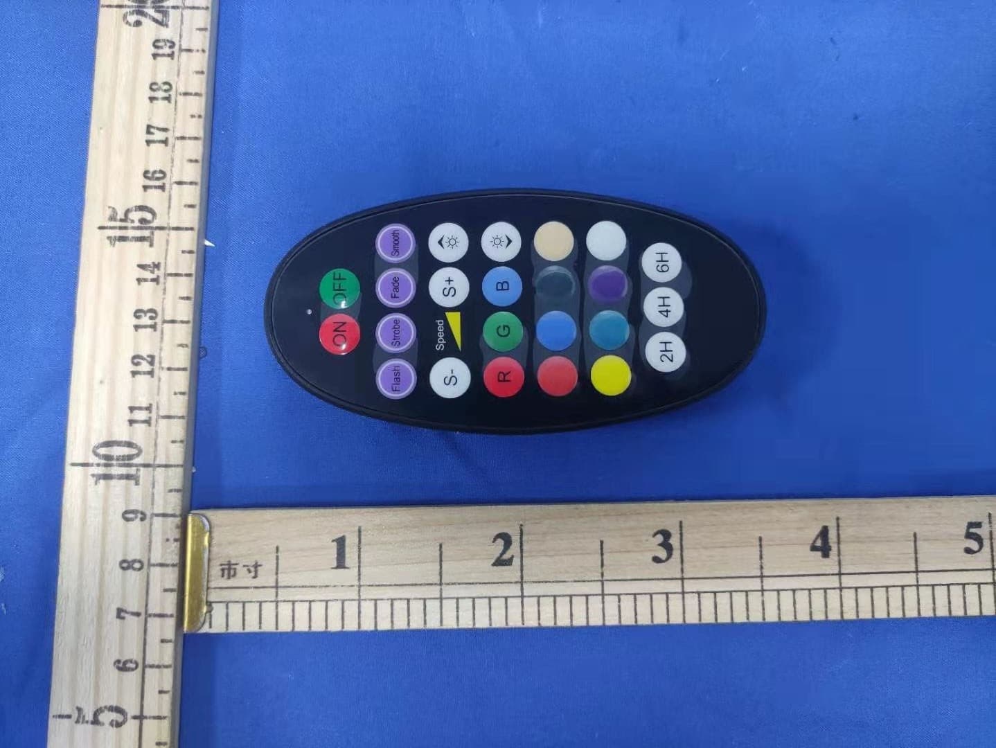
OXGSH03
Mar 15, 2021Flood lights
Equipment Class
DSC - Part 15 Security/Remote Control Transmitter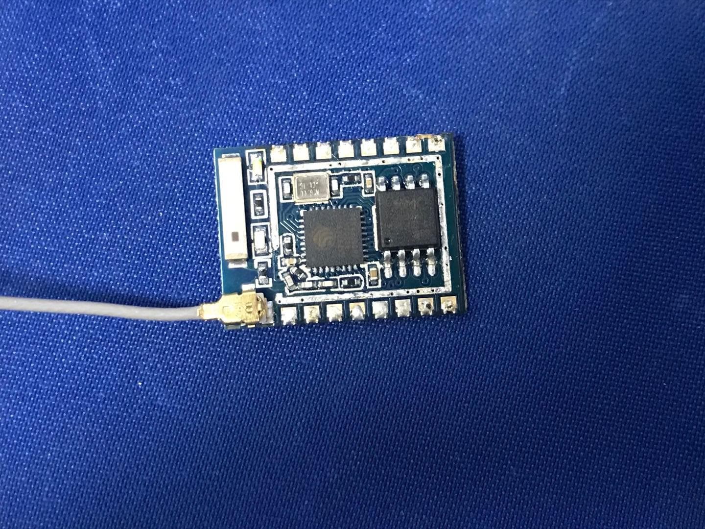
OXGSL90V2
May 06, 2020300L Ultimate light string
Equipment Class
DTS - Digital Transmission System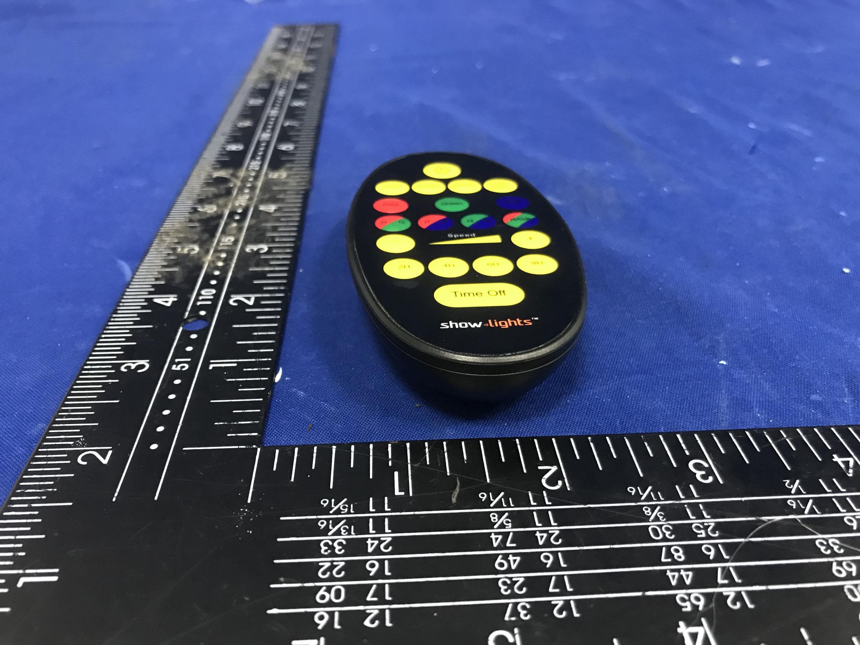
OXGAL28TX
Mar 29, 2020Remote control
Equipment Class
DSC - Part 15 Security/Remote Control Transmitter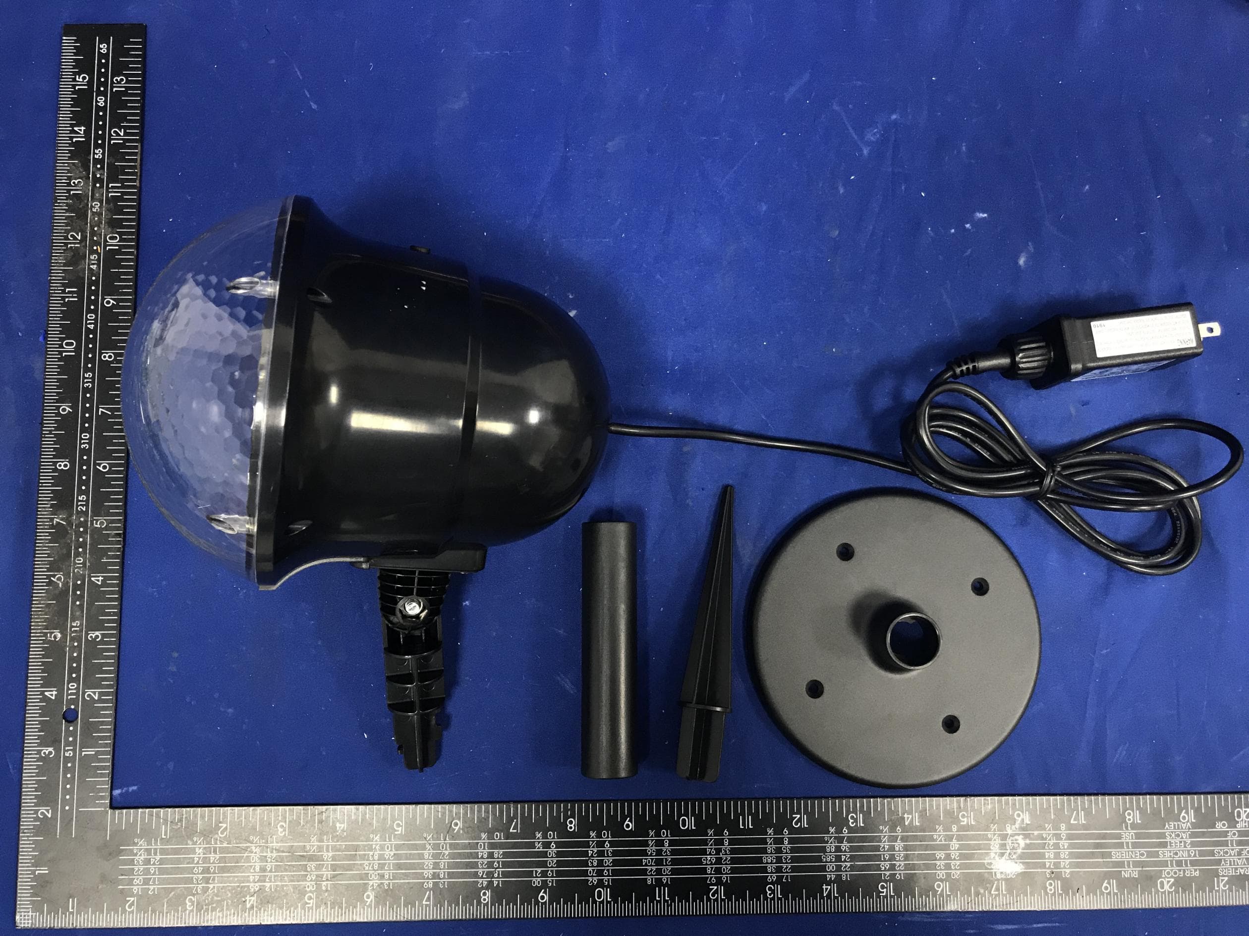
OXGAL28
Mar 25, 2020Super Projector
Equipment Class
JAB - Part 15 Class B Digital Device
OXGZW112
Jun 10, 2015Motion Sensor
Equipment Class
DXT - Part 15 Low Power Transceiver, Rx Verified