OXHSCR001Remote Control Feeder Transmitter
Spin-Cast, Inc.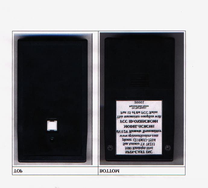
Click to zoom
Application Details
- Equipment Class
- DXX - Part 15 Low Power Communication Device Transmitter
- Date of Grant
- Aug 30, 2001
- Application Purpose
- Original Equipment
- Date of Application
- Aug 30, 2001
- Equipment Note
- Remote Control Feeder Transmitter
- Frequency Range
- 418.00000000 - 418.00000000
- Company
- Spin-Cast, Inc.
- Country
- United States
Documents & Files
Document Text
Text extracted from the exhibit documents filed with the FCC. Open a document above to read the original.
Users Manual
EXHIBIT 3 User’s Manual
Users Manual
Remote Control Installation (SCRC001) Remote Control package contains the following items: Remote Control Transmitter (black plastic box) Remote Control Receiver (circuit board with wire antenna) Powerharness (three plug harness or single plug harness) 4 Nylon “Standoff” Fasteners (white) Connecting the Receiver to Old Style Feeder with LCD Clock and Feed Rate Knob: Cut the motor wires 1 1/2” from the motor and strip about 1/8” of the insulation from all 4 wires. Match colors and twist the wires together (orange with orange and gray with gray). Insert the motor wires into the butt connectors for their respective colors and crimp the connectors. Plug the Powerharness into the receiver circuit and connect the red and black wires to the battery (red “+” and black “-”). Connecting the Receiver to New Style Feeder with Membrane Switch and LCD Display: Unplug the white plug from the back of the circuit board. Plug the Powerharness provided with the remote into the receiver circuit board and into the back of the feeder. Plug the feeder plug into the Powerharness. Mounting the Receiver: The Receiver circuit board will mount on the back of your feeder frame. Remove the battery from your feeder (you do not have to remove the feeder from the barrel, but it may make it easier to measure and drill). Mark the back of the frame. Use the measurements on the attached template drawing. Drill 4 - 1/8” diameter holes and remove all “burrs.” Press the “Standoff” Fasteners into the frame and snap the receiver circuit in place (wire antenna toward the ground). Con- nect the receiver to the feeder. Line up the Bottom Feeder Housing and locate the nearest “weep” hole in the bottom. Enlarge this hole slightly for the antenna wire to exit the feeder. The Transmitter comes with 2 AA batteries installed, so when the Receiver is mounted and connected you are ready to go. The remote control is designed to have minimum battery drain. The Receiver will turn on and off while waiting for a signal from the Transmitter. You may have to hold the button down on the transmitter for several seconds before the feeder starts to spin. The remote has been tested on flat open terrain and found effective at approximately 90 yards. Distance will vary depending on type of barrel you are using (metal, plastic or fiberglas) and terrain in your area. 2000 SPIN-CAST, INC.C FCC Compliance: This equipment has been tested and found to comply with the limits for a Class B digital device, pursuant to Part 15 of the FCC rules. These limits are design to provide reasonable protection against harmful interference in a residential installation. This equipment generates, uses and can radiate radio frequency energy and if not installed and used in accordance with the instruc- tions, may cause harmful interference to radio communications. However, there is no guarantee that interference will not occur in a particular installation. If this equipment does cause harmful interfer- ence to radio or television reception, which can be determined by turning the equipment off and on, the user in encouraged to try to correct the interference by one or more of the following measures: Reorient or relocate the receiving antenna. Increase the separation between the equipment and the receiver. Connect the equipment into an outlet on a circuit different from that to which the receiver is connected. Consult the dealer or an experienced radio/TV technician for help. Note: Operation is subject to the following two conditions: (1) This device may not cause harmful interference, and (2) this device must accept any interference received, including interference that may cause undesired operation. Spin-Cast Inc 5680 Randolph Blvd San Antonio TX 78233 Phone: 210-653-7514 2000 SPIN-CAST, INC.C 1” 1 1 / 8 ” 1 / 8 ” 3 5 / 8 ” rearview of feeder mounting frame holes for remote control are 1 / 8 ” dia. REMOTE CONTROL RECEIVER MOUNTING TEMPLATE NOTE: FOR BEST RESULTS MOUNT THE RECEIVER CIRCUIT BOARD EVEN WITH THE BOTTOM OF THE FRAME. 2000 SPIN-CAST, INC.C Remote Control Receiver Circuit mounted on Frame 2000 SPIN-CAST, INC.C
Cover Letter(s)
EXHIBIT 10 Cover Letters (Agent Authorization Letter and Anti-Drug Statement)
Cover Letter(s)
American Telecommunications Certification Body Inc. 6731 Whittier Ave, McLean, VA 22101 July 20, 2001 RE: Spin-Cast Inc. FCC ID: OXHSCRC001 I have just a few brief comments on the Exhibits associated with this Application. 1.) The labeling for this device does not conform to the requirements of 15.19. If the device is smaller than the palm of the hand, the two-part statement of 15.19(a)(3) may appear in the manual. Please resubmit corrected Exhibits. 2.) The internal photographs are of insufficient detail. Please submit full sized photos of both sides of printed wiring board with all RF shielding removed. Submit just one to a page of sufficient quality to distinguish the individual components on the board. Orthographic views are preferred. 3.) Am not certain if additional information could be derived from better external photos, but clearer ones might be helpful. That’s it. Get me these updated Exhibits and your Grant will be issued. Bill William H. Graff Examining Engineer President and Director of Engineering mailto:[email protected] The items indicated above must be submitted before processing can continue on the above referenced application. Failure to provide the requested information may result in application termination. Correspondence should be considered part of the permanent submission and may be viewed from the Internet after a Grant of Equipment Authorization is issued. Please do not respond to this correspondence using the email reply button. In order for your response to be processed expeditiously, you must submit your documents through the AmericanTCB.com website. Also, please note that partial responses increase processing time and should not be submitted. Any questions about the content of this correspondence should be directed to the sender.
External Photos
EXHIBIT 6 External Photographs Spin-Cast, Inc.
ID Label/Location Info
EXHIBIT 2 Label and Label Placement Spin-Cast, Inc. Remote Transmitter Label Spin-Cast, Inc. Remote Transmitter Label Placement
Internal Photos
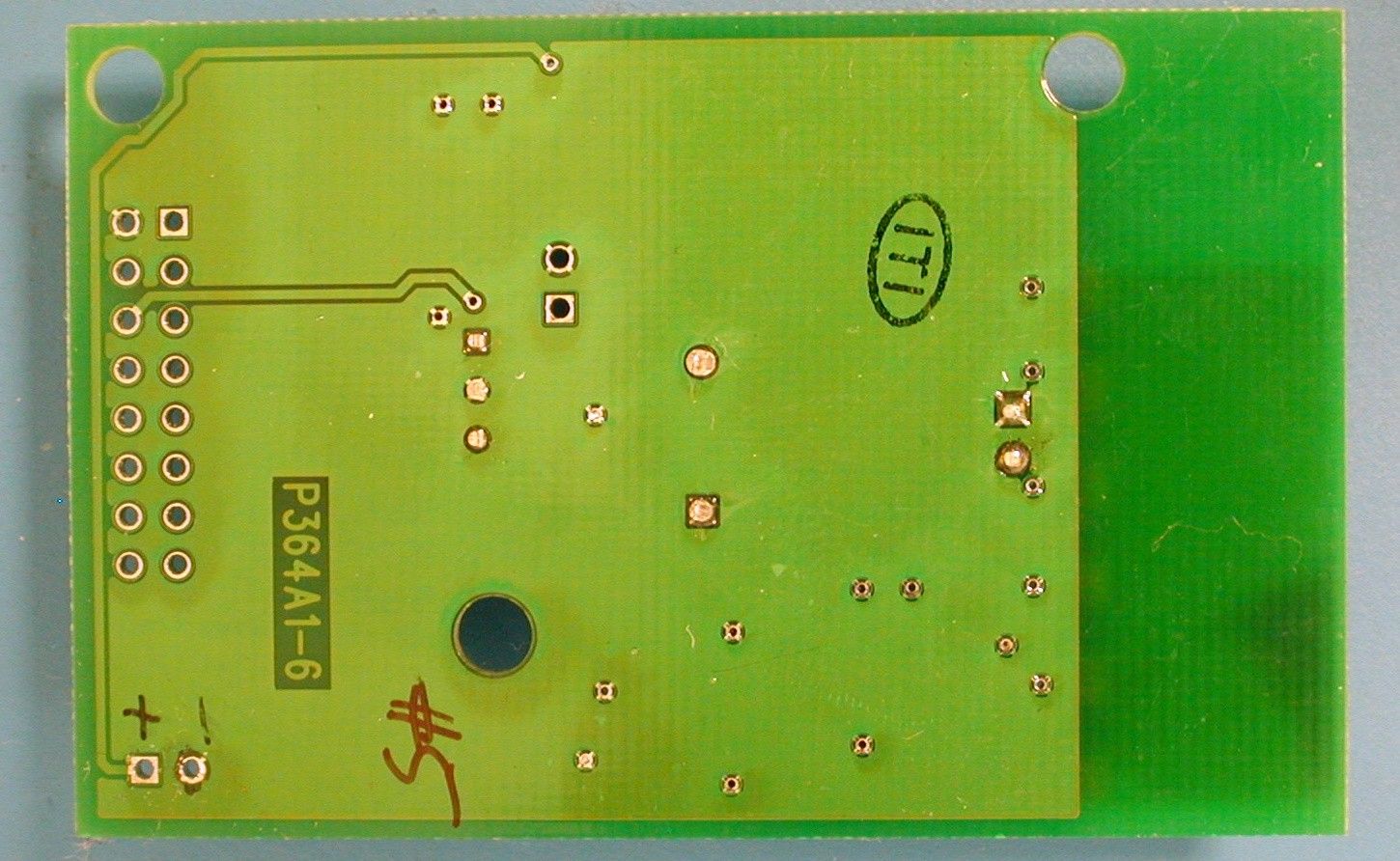
EXHIBIT 5 Internal Photographs SPIN-CAST, INC. SCRC001 - Internal
Internal Photos
XmtrPCBtop.jpg (640x480x16M jpeg)
Operational Description
EXHIBIT 1 Operational Description The Equipment Under Test (EUT) is a Spin-Cast, Inc. SCRC001. The SCRC001 is a low power hand-held wireless remote transmitter designed to activate a remote controlled feeder. The SCRC001 is powered by 2 AA batteries.
Test Report
FCC ID#: OXHSCRC001 Page 1 EXHIBIT 7 Test Report FCC ID#: OXHSCRC001 Page 2 Table of Contents Table of Contents......................................................................................................................19 Certificate of Compliance.........................................................................................................20 1.0 EUT Description.................................................................................................................4 1.1 EUT Operation....................................................................................................................4 2.0 Electromagnetic Emissions Testing.....................................................................................4 2.1 Test Procedure.................................................................................................................5 2.2 Test Criteria...................................................................................................................5 2.3 Test Results.....................................................................................................................5 3.0 Occupied Bandwidth Measurements....................................................................................5 3.1 Test Procedure.................................................................................................................6 3.2 Test Criteria....................................................................................................................6 3.3 Test Results.....................................................................................................................6 4.0 Antenna Requirement..........................................................................................................6 4.1 Evaluation Procedure......................................................................................................6 4.2 Evaluation Criteria..........................................................................................................6 4.3 Evaluation Results...........................................................................................................7 5.0 Modifications to Equipment................................................................................................7 6.0 List of Test Equipment........................................................................................................7 Figures Figure 1: Radiated Emissions Test Setup...................................................................................23 Appendices Appendix A: Fundamental Emissions Test Data........................................................................24 THIS REPORT SHALL NOT BE REPRODUCED EXCEPT IN FULL, WITHOUT THE WRITTEN APPROVAL OF PROFESSIONAL TESTING (EMI), INC. FCC ID#: OXHSCRC001 Page 3 Applicant: SPIN-CAST, INC. Applicant’s Address: 5680 Randolph Blvd. San Antonio, Texas 78233 Model: SCRC001 Serial Number: 005 Project Number: 01415-10 Test Dates: April 19, 2001 I, Jeffrey A. Lenk, for Professional Testing (EMI), Inc., being familiar with the FCC rules and test procedures have reviewed the test setup, measured data and this report. I believe them to be true and accurate. The SPIN-CAST INC., SCRC001 was tested to and found to be in compliance with FCC Part 15 Subpart C for an Intentional Radiator. The highest emissions generated by the above equipment are listed below: Frequency (MHz) Level (dBμV/m) Limit (dBμV/m) Margin (dB) Fundamental 418 79.9 80.3 -0.4 Spurious 2090 49.2 63.5 -14.3 Occupied Bandwidth 190 KHz measured at –20 dBC. Fundamental frequency is 418 MHz. ______________________________ Jeffrey A. Lenk President Certificate of Compliance Page 4 1.0 EUT Description The Equipment Under Test (EUT) is a Spin-Cast, Inc. SCRC001. The SCRC001 is a low power hand-held wireless remote transmitter designed to activate a remote controlled feeder. The SCRC001 is powered by 2 AA batteries. The transmission continues until the button is released. Once the button is released, the transmission stops instantly as power is removed from the entire circuit. The EUT operates at 418 MHz and is designed fro compliance with 47 CFR 15.231 of the FCC rules. Specific test requirements for this device include the following: 47 CFR 15.231 Fundamental Transmit Power 47 CFR 15.231& 15.205 Spurious Radiated Power 47 CFR 15.231 Occupied Bandwidth (ANSI C63.4 used as Procedural Reference) 47 CFR 15.203 Antenna Requirement The system tested consisted of the following: Manufacturer & Model Serial # FCC ID # Description SPIN-CAST, INC., SCRC001 005 OXHSCSR001 SCRC001 1.1 EUT Operation The SCRC001 was tested with the transmit button continuously depressed, thus the SCRC001 was continuously transmitting. 2.0 Electromagnetic Emissions Testing Professional Testing (EMI), Inc. (PTI), follows the guidelines of NIST for all uncertainty calculations, estimates and expressions thereof for EMC testing. Radiated emission measurements were made of the Fundamental and Spurious Emission levels for the SCRC001. Measurements of the occupied bandwidth were also made for the equipment. Measurements of the maximum emission levels for the fundamental and the spurious/harmonic emissions of the SCRC001 were made at the Professional Testing "Open Field" Site #3, located in Round Rock, Texas to determine the radio noise radiated from the EUT. A “Description of Measurement Facilities” has been submitted to the FCC and approved pursuant to Section 2.948 of CFR 47 of the FCC rules. Tests of the fundamental emissions for the device were performed to determine the worst case polarization of the device. The fundamental emissions of the device were measured with the device in its position of use and the measurement antenna was changed to both vertical and horizontal polarity to record the signal of highest intensity. FCC ID#: OXHSCRC001 Page 5 2.1 Test Procedure The EUT was placed on a non-conductive table 0.8 me…
Text truncated - open the document above for the full version.
Test Setup Photos
EXHIBIT 8 Test Set-Up Photographs Test Setup Photographs SPIN-CAST, INC. Radiated Emissions – Front View Micro Wave Radiated Emissions
Contact Information
Applicant
Jeane Cureton(President/Owner)
Technical Contact
Professional Testing (EMI), IncJeffery A Lenk
[email protected]512 244 3371
1601 FM 1460 · Round Rock, Texas · United States
Test Firm
Professional Testing (EMI), Inc.Jeff Link
Technical Specifications
| # | Rule Parts | Frequency Range | Power Output |
|---|---|---|---|
| 1 | 15C | 418 MHz - 418 MHz | - |
Other Applications from Spin-Cast, Inc.
OXHSCRC001
Aug 23, 2001Part 15.231
Equipment Class
DXX - Part 15 Low Power Communication Device Transmitter