OXN1900MTDMABASE31.9GHz Wireless Base Station Unit (WBSU)
Mitsubishi Electric Corporation, Communication Systems Business Division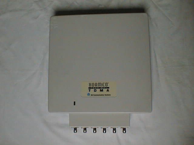
Click to zoom
Application Details
- Equipment Class
- PCB - PCS Licensed Transmitter
- Date of Grant
- May 16, 2000
- Application Purpose
- Original Equipment
- Date of Application
- Apr 06, 2000
- Equipment Note
- 1.9GHz Wireless Base Station Unit (WBSU)
- Frequency Range
- 1930.00000000 - 1990.00000000
- Country
- Japan
Documents & Files
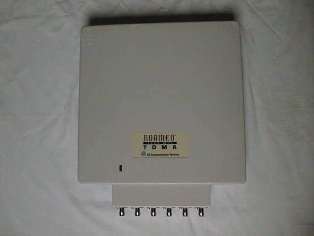
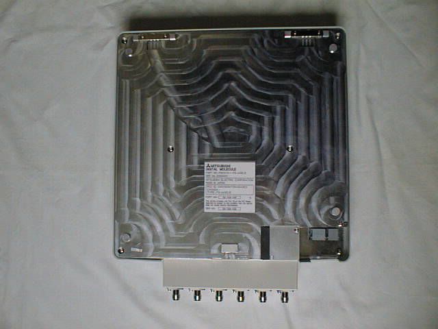
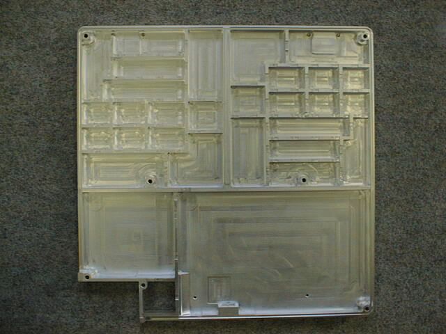
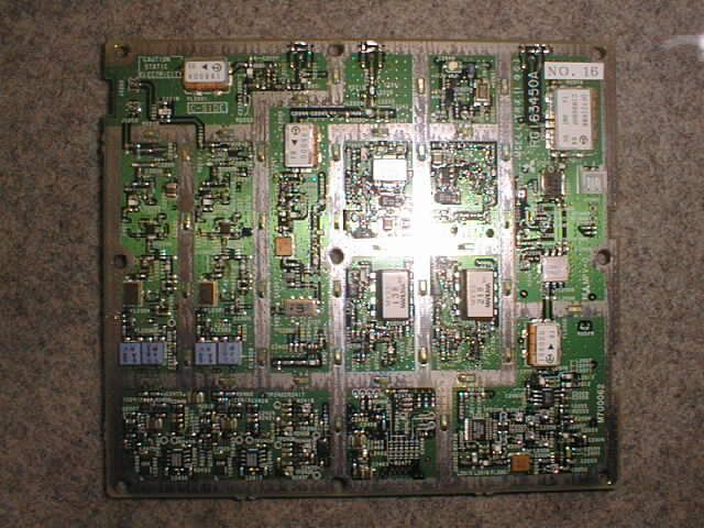
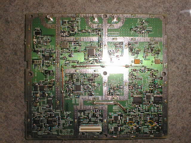
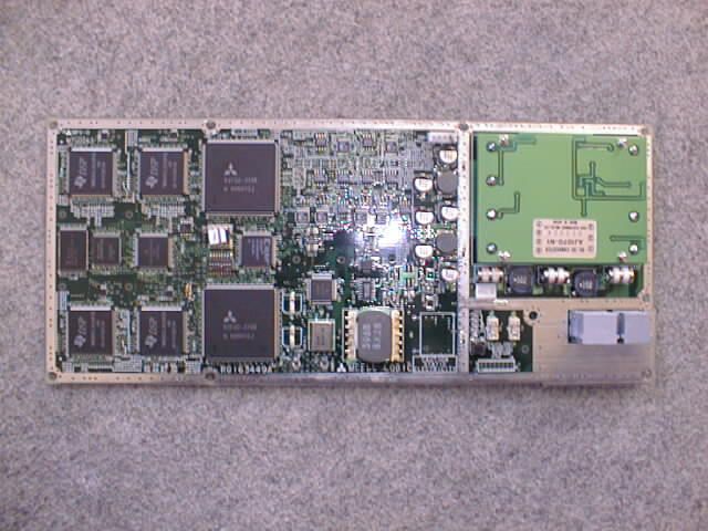
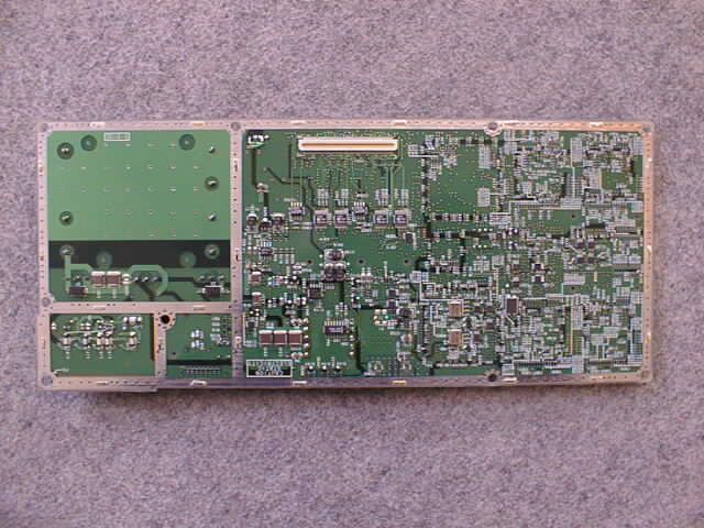
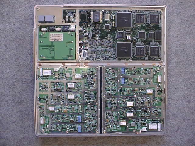
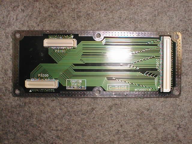
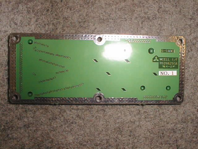
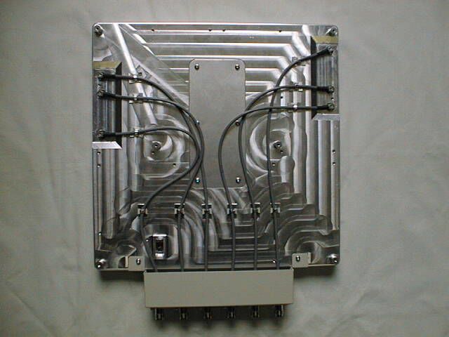
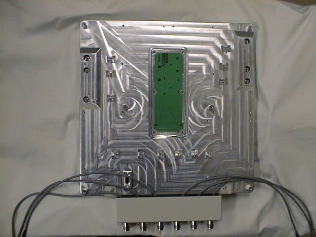
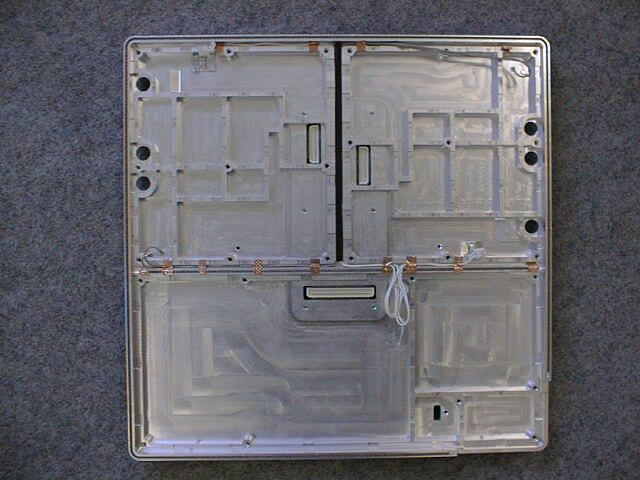
Document Text
Text extracted from the exhibit documents filed with the FCC. Open a document above to read the original.
Users Manual
“”
Cover Letter(s)
April 10, 2000 To: To whom it may concern Equipment Authorization Branch Federal Communications Commission Equipment Authorization Branch Subject: Electronic submission for FCC ID: OXN1900MTDMABASE3 Gentlemen: We would like to send these files for equipment authorization at the following schedule. Sending schedule (JST) April 10, 2000 : Cover letter : FCC ID label (3 files) : External photos (1 file) : Internal photos (11 files) : Users manual (1 file) : Test report (1 file) : Test setup photos (1 file) : Schematics (4 files) : Block diagram (2 files) Yours faithfully, (Ms) Makoto Okada EMC Div. Japan Quality Assurance Organization (JQA) Kita-Kansai Testing Center [email protected]
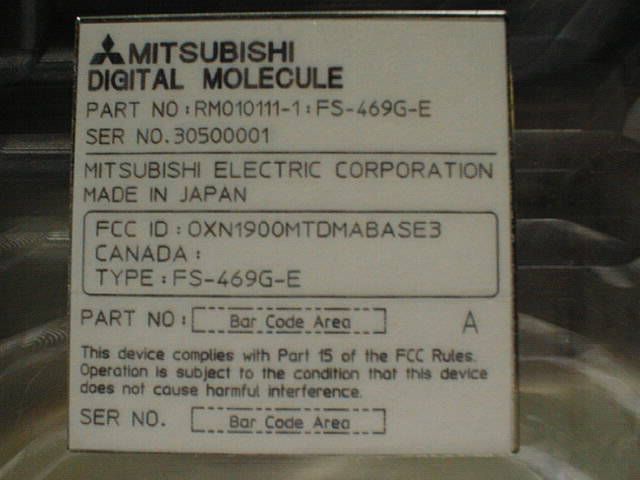
ID Label/Location Info
(UnitÅFmm) BarCodeArea RM010111-1ÅFFS-469G-E 30500001 SERNOÅD A PARTNOÅF TYPEÅFFS-469G-E CANADAÅF FCCIDÅFOXN1900MTDMABASE3 MADEINJAPAN MITSUBISHIELECTRICCORPORATION SERNOÅD PARTNOÅF MITSUBISHI DIGITALMOLECULE BarCodeArea 6 3 63 doesnotcauseharmfulinterference. Operationissubjecttotheconditionthatthisdevice ThisdevicecomplieswithPart15oftheFCCRules.
Test Report
IssueDate:April6,2000 Page 1 of 50 EMC EMISSION - TEST REPORT JQA APPLICATION No.: KL80000004 Name of Product: 1.9GHz Wireless Base Station Unit (WBSU) Model/Type No.: FS-469G-E FCC ID: OXN1900MTDMABASE3 Applicant : MITSUBISHI ELECTRIC CORPORATION COMMUNICATION SYSTEMS BUSINESS DIVISION Address : 8-1-1, TSUKAGUCHI-HONMACHI, AMAGASAKI CITY, HYOGO 661-8661, JAPAN Manufacturer : MITSUBISHI ELECTRIC CORPORATION COMMUNICATION SYSTEMS BUSINESS DIVISION Address : 8-1-1, TSUKAGUCHI-HONMACHI, AMAGASAKI CITY, HYOGO 661-8661, JAPAN Receive date of TUT: March 22, 2000 Final Judgement :Passed TEST RESULTS IN THIS REPORT are obtained in use of equipment that is traceable to Electro- technical Lab. of MITI Japan and Communications Research Lab. of PTT Japan. THE TEST RESULTS only responds to the test sample. This test report shall not be reproduced except in full. JQA Application No. : KL80000004Regulation : CFR 47 FCC Rules Part 24 Model No.: FS-469G-EIssue Date : April 6, 2000 FCC ID: OXN1900MTDMABASE3 Page 2 of 50 DIRECTORY Page A) Documentation Directory2 Test Regulation / General Information3 - 10 Test Conditions11 - 22 Configuration of TUT / Operation mode of the TUT23 - 26 TUT Modification / Responsible Party27 Test results / Measurement Uncertainty28 - 29 Summary30 Test System-Arrangement (Drawings) 31 Test-setup (Photographs) at worst case 32 B) Test data Transmitter Power(TP)33 Antenna Spurious Conducted Emission34 - 37 Occupied Bandwidth38 - 41 Unwanted Radiation42 - 45 Frequency Stability46 - 49 Maximum Permissible Exposure(MPE)50 JQA Application No. : KL80000004Regulation : CFR 47 FCC Rules Part 24 Model No.: FS-469G-EIssue Date : April 6, 2000 FCC ID: OXN1900MTDMABASE3 Page 3 of 50 TEST REGULATION FCC Rules and Regulations Part 24 (October 1, 1998) ô- Narrowband PCS ò- Broadband PCS Test procedure: The tests were performed according to FCC Rules Regulations Part 2 (October 1, 1999), and ANSI C63.4 (1992). GENERAL INFORMATION Test facility: 1) Test Facility located at Kita-Kansai : 1st and 2nd Open Sites (3 m Site) Test Facility located at Kameoka Open Site (3, 10 and 30 m, on common plane) FCC filing No. : 31040/SIT 1300F2 2) KITA-KANSAI TESTING CENTER is recognized under the National Voluntary Laboratory Accreditation Program for satisfactory compliance established in Title 15, Part 285 Code of Federal Regulations. NVLAP Lab Code: 200191-0 Definitions for symbols used in this test report: ò- Black box indicates that the listed condition, standard or equipment is applicable for this Report. ô- Blank box indicates that the listed condition, standard or equipment is not applicable for this Report. JQA Application No. : KL80000004Regulation : CFR 47 FCC Rules Part 24 Model No.: FS-469G-EIssue Date : April 6, 2000 FCC ID: OXN1900MTDMABASE3 Page 4 of 50 Description of the Transmitter Under Test (TUT): 1) Name: 1.9GHz Wireless Base Station unit (WBSU) 2) Model/Type No.: FS-469G-E 3) Product Type: Prototype(Serial No. : 30500001) 4) Category: Broadband PCS 5) TUT Authorization: - Verification- Certification- D.o.C.ôòô 6) Transmitting Frequency: 1930.080 MHz (2 ch) - 1989.960 MHz (1998 ch) 7) Receiving Frequency: 1850.040 MHz (2 ch) - 1909.92 MHz (1998 ch) 8) Emission Designations: 32K3D7W 9) Nominal ERP: 0.1 W 10) Power Rating: -24Vdc ~ -48Vdc JQA Application No. : KL80000004Regulation : CFR 47 FCC Rules Part 24 Model No.: FS-469G-EIssue Date : April 6, 2000 FCC ID: OXN1900MTDMABASE3 Page 5 of 50 General Description of the TUT : The TDMA system is the medium for the linking calls between PBX and non-public systems users and mobile users. The system also enables a mobile user to communicate with other mobiles. This Wireless Base Station Unit(WBSU) is the distributed radio component of a 1.9 GHz PCS System that is being developed for the operation in the licensed PCS holder. The WBSU is being developed as a subsystem component. The WBSU provides the IS-136A air interface to handheld mobiles operating as a private in-building or campus system. The WBSU is connected to the centralized system controller through a dedicated line interface. This interface utilizes a RJ45 physical connector(modular). This cable connection from the controller to the WBSU provides the following signals. (1) -48Vdc power to supply a WBSU. (2) The clock source of 128kHz for the WBSU to control the frequency accuracy. (3) ISDN BRI(Basic Rate Interface) signal to control the communications. The voltage of -48Vdc generated at the controller gets lower as it comes to the WBSU by its consumption current through the line cable. It can operate at the input line voltage of -48Vdc to -24Vdc. An internal power supply circuit in the WBSU converts the DC input voltage into the internal working voltage of 5V and 3.6V. The WBSU is approximately 12" ◊ 12" ◊ 3". The unit weighs approximately 4kg. A security screw is provided which requires a special tool for removal. The antennas (TX1 and TX2) are integrated to the WBSU and are contained within the assembly. The operating frequency range of the WBSU is the standard licensed bands within the PCS spectrum. The output level of the transceiver is from -10dBW to -38 dBW and is software controlled. The network connections to provide voice or data communications through to the PSTN(Public Switched Telephone Network) or PBX are provided by the central controller and are not part of the WBSU. The TDMA system is the medium for linking calls between PBX and non-public system users and mobile users. The system also enables a mobile user to communicate with other mobiles. In a typical installation, the WBSU (called External Antenna Type) is supposed to have an external antenna system attached, as indicated in the drawing, to distribute the transmitted power into the offices of a building. This antenna system is a standard product made in the U.S. There is another similar type of base station (called Internal Antenna Type) which has antennas connected inside the housing. The Internal-antenna-type base s…
Text truncated - open the document above for the full version.
Test Report
Page 1 of 2 Frequency Stability Measurement Measurement Results: a) Frequency Stability Measurement versus Temperature a-1-a) Transmitting(Reference) Frequency : 1930.080 MHz Antenna terminal : TX1 Supply voltage to the Power and Clock Distribution Box for the TUT : -48.0 Vdc Test Date: April 2, 2000 AmbientDeviation (ppm) TemperatureStartup2 minutes 5 minutes10 minutes (°C) -30<0.10<0.10<0.10<0.10 -20<0.10<0.10<0.10<0.10 -10<0.10<0.10<0.10<0.10 0<0.10<0.10<0.10<0.10 +10<0.10<0.10<0.10<0.10 +20<0.10<0.10<0.10<0.10 +30<0.10<0.10<0.10<0.10 +40<0.10<0.10<0.10<0.10 +50<0.10<0.10<0.10<0.10 a-1-b) Transmitting(Reference) Frequency : 1989.960MHz Antenna terminal : TX1 Supply voltage to the Power and Clock Distribution Box for the TUT : -48.0 Vdc Test Date: April 2, 2000 AmbientDeviation (ppm) TemperatureStartup2 minutes 5 minutes10 minutes (°C) -30<0.10<0.10<0.10<0.10 -20<0.10<0.10<0.10<0.10 -10<0.10<0.10<0.10<0.10 0<0.10<0.10<0.10<0.10 +10<0.10<0.10<0.10<0.10 +20<0.10<0.10<0.10<0.10 +30<0.10<0.10<0.10<0.10 +40<0.10<0.10<0.10<0.10 +50<0.10<0.10<0.10<0.10 JQA Application No. : KL80000004ARegulation : CFR 47 FCC Rules Part 24 Model No.: FS-469G-EIssue Date : May 8, 2000 FCC ID: OXN1900MTDMABASE3 Page 2 of 2 a-2-a) Transmitting(Reference) Frequency : 1930.080 MHz Antenna terminal : TX2 Supply voltage to the Power and Clock Distribution Box for the TUT : -48.0 Vdc Test Date: April 2, 2000 AmbientDeviation (ppm) TemperatureStartup2 minutes 5 minutes10 minutes (°C) -30<0.10<0.10<0.10<0.10 -20<0.10<0.10<0.10<0.10 -10<0.10<0.10<0.10<0.10 0<0.10<0.10<0.10<0.10 +10<0.10<0.10<0.10<0.10 +20<0.10<0.10<0.10<0.10 +30<0.10<0.10<0.10<0.10 +40<0.10<0.10<0.10<0.10 +50<0.10<0.10<0.10<0.10 a-2-b) Transmitting(Reference) Frequency : 1989.960 MHz Antenna terminal : TX2 Supply voltage to the Power and Clock Distribution Box for the TUT : -48.0 Vdc Test Date: April 2, 2000 AmbientDeviation (ppm) TemperatureStartup2 minutes 5 minutes10 minutes (°C) -30<0.10<0.10<0.10<0.10 -20<0.10<0.10<0.10<0.10 -10<0.10<0.10<0.10<0.10 0<0.10<0.10<0.10<0.10 +10<0.10<0.10<0.10<0.10 +20<0.10<0.10<0.10<0.10 +30<0.10<0.10<0.10<0.10 +40<0.10<0.10<0.10<0.10 +50<0.10<0.10<0.10<0.10 Note : The measurement were made after all of components of the oscillator sufficiently stabilized at each temperature. Tester Signature : Type Name: Akio Hosoda JQA Application No. : KL80000004ARegulation : CFR 47 FCC Rules Part 24 Model No.: FS-469G-EIssue Date : May 8, 2000 FCC ID: OXN1900MTDMABASE3
Test Report
Page 1 of 2 Frequency Stability Measurement Measurement Results: a) Frequency Stability Measurement versus Temperature a-1-a) Transmitting(Reference) Frequency : 1930.080 MHz Antenna terminal : TX1 Supply voltage to the Power and Clock Distribution Box for the TUT : -48.0 Vdc Test Date: April 2, 2000 AmbientDeviation (ppm) TemperatureStartup2 minutes 5 minutes10 minutes (°C) -30<0.10<0.10<0.10<0.10 -20<0.10<0.10<0.10<0.10 -10<0.10<0.10<0.10<0.10 0<0.10<0.10<0.10<0.10 +10<0.10<0.10<0.10<0.10 +20<0.10<0.10<0.10<0.10 +30<0.10<0.10<0.10<0.10 +40<0.10<0.10<0.10<0.10 +50<0.10<0.10<0.10<0.10 a-1-b) Transmitting(Reference) Frequency : 1989.960MHz Antenna terminal : TX1 Supply voltage to the Power and Clock Distribution Box for the TUT : -48.0 Vdc Test Date: April 2, 2000 AmbientDeviation (ppm) TemperatureStartup2 minutes 5 minutes10 minutes (°C) -30<0.10<0.10<0.10<0.10 -20<0.10<0.10<0.10<0.10 -10<0.10<0.10<0.10<0.10 0<0.10<0.10<0.10<0.10 +10<0.10<0.10<0.10<0.10 +20<0.10<0.10<0.10<0.10 +30<0.10<0.10<0.10<0.10 +40<0.10<0.10<0.10<0.10 +50<0.10<0.10<0.10<0.10 JQA Application No. : KL80000004ARegulation : CFR 47 FCC Rules Part 24 Model No.: FS-469G-EIssue Date : May 8, 2000 FCC ID: OXN1900MTDMABASE3 Page 2 of 2 a-2-a) Transmitting(Reference) Frequency : 1930.080 MHz Antenna terminal : TX2 Supply voltage to the Power and Clock Distribution Box for the TUT : -48.0 Vdc Test Date: April 2, 2000 AmbientDeviation (ppm) TemperatureStartup2 minutes 5 minutes10 minutes (°C) -30<0.10<0.10<0.10<0.10 -20<0.10<0.10<0.10<0.10 -10<0.10<0.10<0.10<0.10 0<0.10<0.10<0.10<0.10 +10<0.10<0.10<0.10<0.10 +20<0.10<0.10<0.10<0.10 +30<0.10<0.10<0.10<0.10 +40<0.10<0.10<0.10<0.10 +50<0.10<0.10<0.10<0.10 a-2-b) Transmitting(Reference) Frequency : 1989.960 MHz Antenna terminal : TX2 Supply voltage to the Power and Clock Distribution Box for the TUT : -48.0 Vdc Test Date: April 2, 2000 AmbientDeviation (ppm) TemperatureStartup2 minutes 5 minutes10 minutes (°C) -30<0.10<0.10<0.10<0.10 -20<0.10<0.10<0.10<0.10 -10<0.10<0.10<0.10<0.10 0<0.10<0.10<0.10<0.10 +10<0.10<0.10<0.10<0.10 +20<0.10<0.10<0.10<0.10 +30<0.10<0.10<0.10<0.10 +40<0.10<0.10<0.10<0.10 +50<0.10<0.10<0.10<0.10 Note : The measurement were made after all of components of the oscillator sufficiently stabilized at each temperature. Tester Signature : Type Name: Akio Hosoda JQA Application No. : KL80000004ARegulation : CFR 47 FCC Rules Part 24 Model No.: FS-469G-EIssue Date : May 8, 2000 FCC ID: OXN1900MTDMABASE3
Test Setup Photos
Radiated Emission Front View Rear View
Contact Information
Applicant
Kazuo Kimura(General Manager)
Technical Contact
Japan Quality Assurance Org.Kosei Shibata
[email protected]81-727-29-2246
7-7, Ishimaru 1-Chome, · Osaka · Japan
Non-Technical Contact
Japan Quality Assurance Org.Makoto Okada
[email protected]81-727-29-2246
Test Firm
Japan Quality Assurance Org.Katsumi Nishii
Technical Specifications
| # | Rule Parts | Frequency Range | Power Output | Emission | Tolerance |
|---|---|---|---|---|---|
| 1 | 24E | 1.93 GHz - 1.99 GHz | 100.00 mW | 32K3D7W | 0.1000000000 ppm |
Other Applications from Mitsubishi Electric Corporation, Communication Systems Business Division
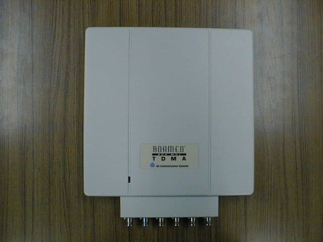
OXN800MTDMABASE3
Nov 08, 2000800MHz Wireless Base Station Unit (WBSU)
Equipment Class
TNB - Licensed Non-Broadcast Station Transmitter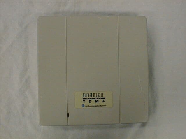
OXN800MTDMABASE2
Aug 10, 2000800MHz Wireless Base Station Unit (WBSU)
Equipment Class
TNB - Licensed Non-Broadcast Station Transmitter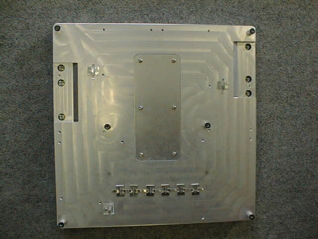
OXN1900MTDMABASE2
May 14, 2000PCB - PCS Licensed Transmitter
Equipment Class
PCB - PCS Licensed Transmitter