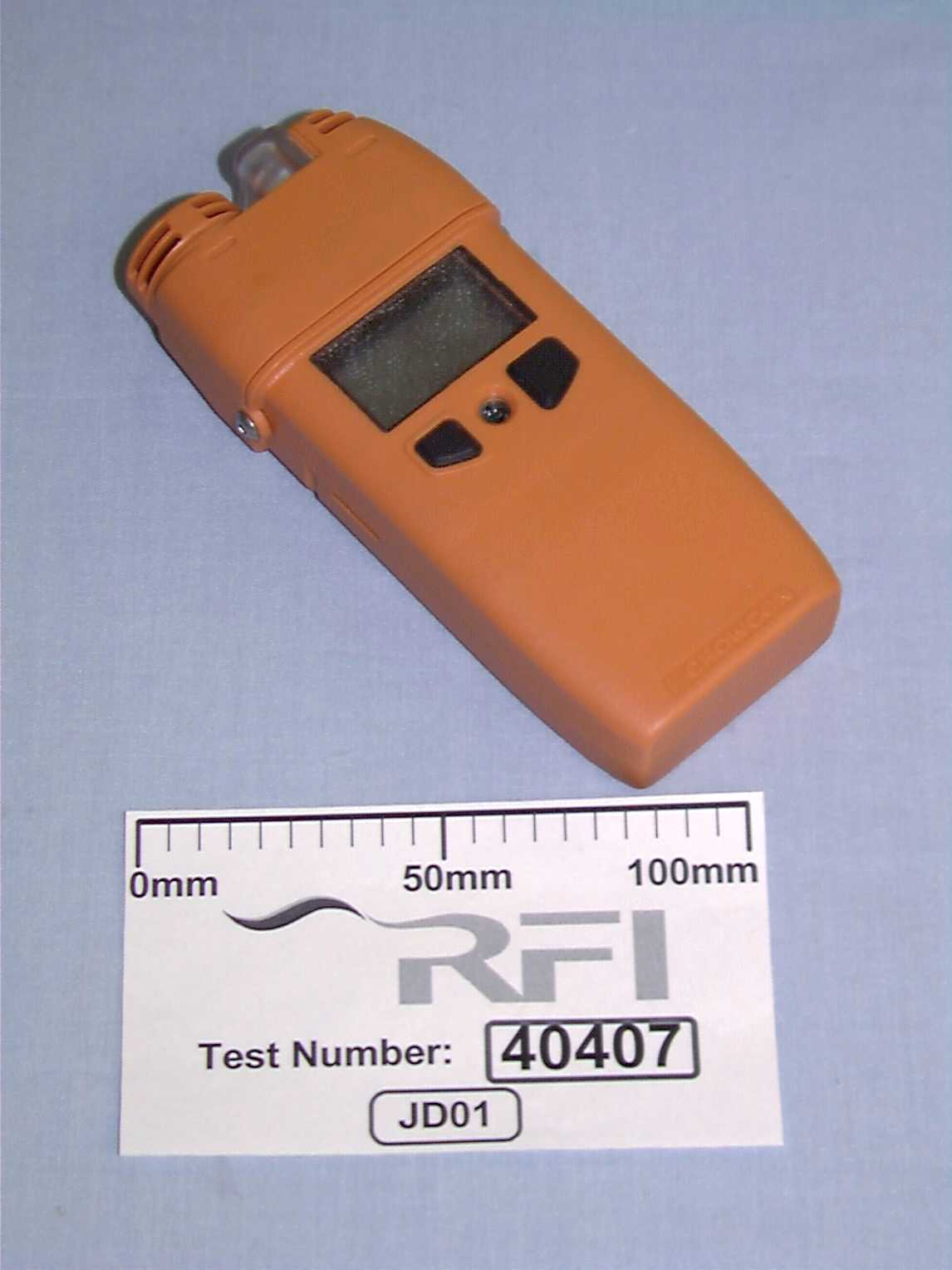
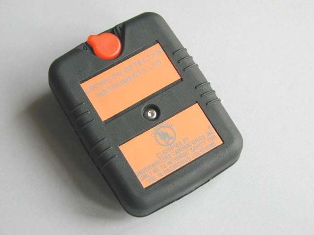
OXOGASMANIIGasman 11 Portable Gas Detector
Crowcon Detection Instruments Ltd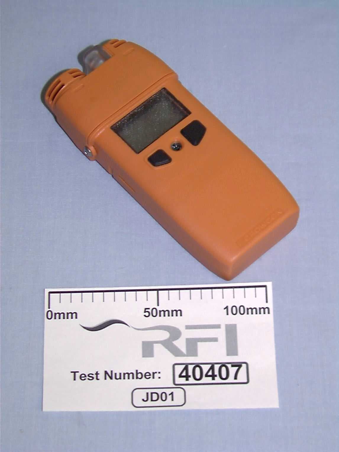
Click to zoom
Application Details
- Equipment Class
- DXX - Part 15 Low Power Communication Device Transmitter
- Date of Grant
- Jul 26, 2000
- Application Purpose
- Original Equipment
- Date of Application
- Mar 16, 2000
- Equipment Note
- Gasman 11 Portable Gas Detector
- Frequency Range
- 418.00000000 - 418.00000000
- Country
- United Kingdom
Documents & Files
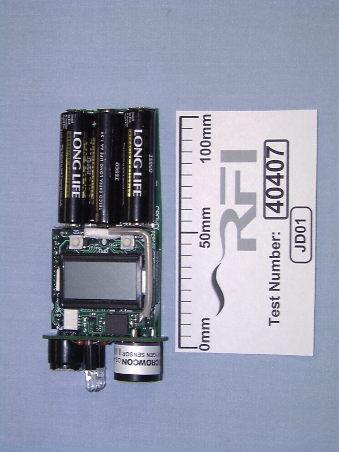
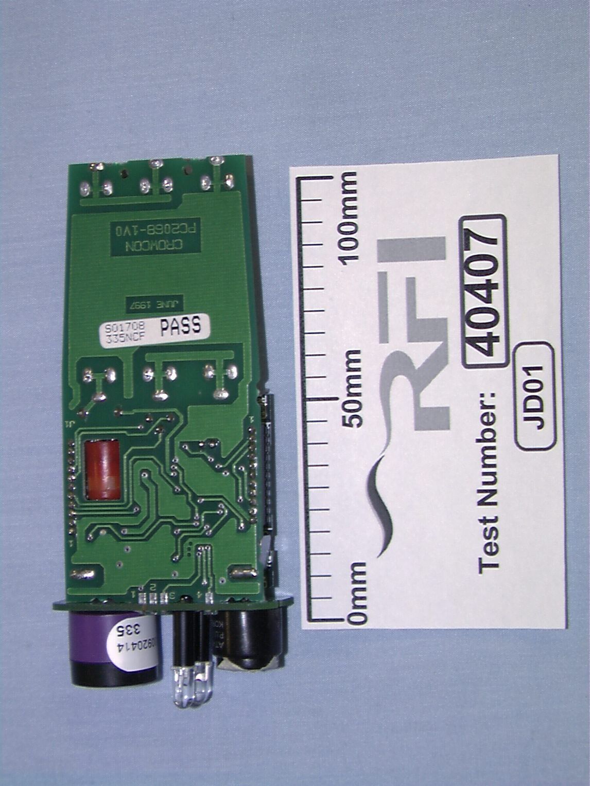
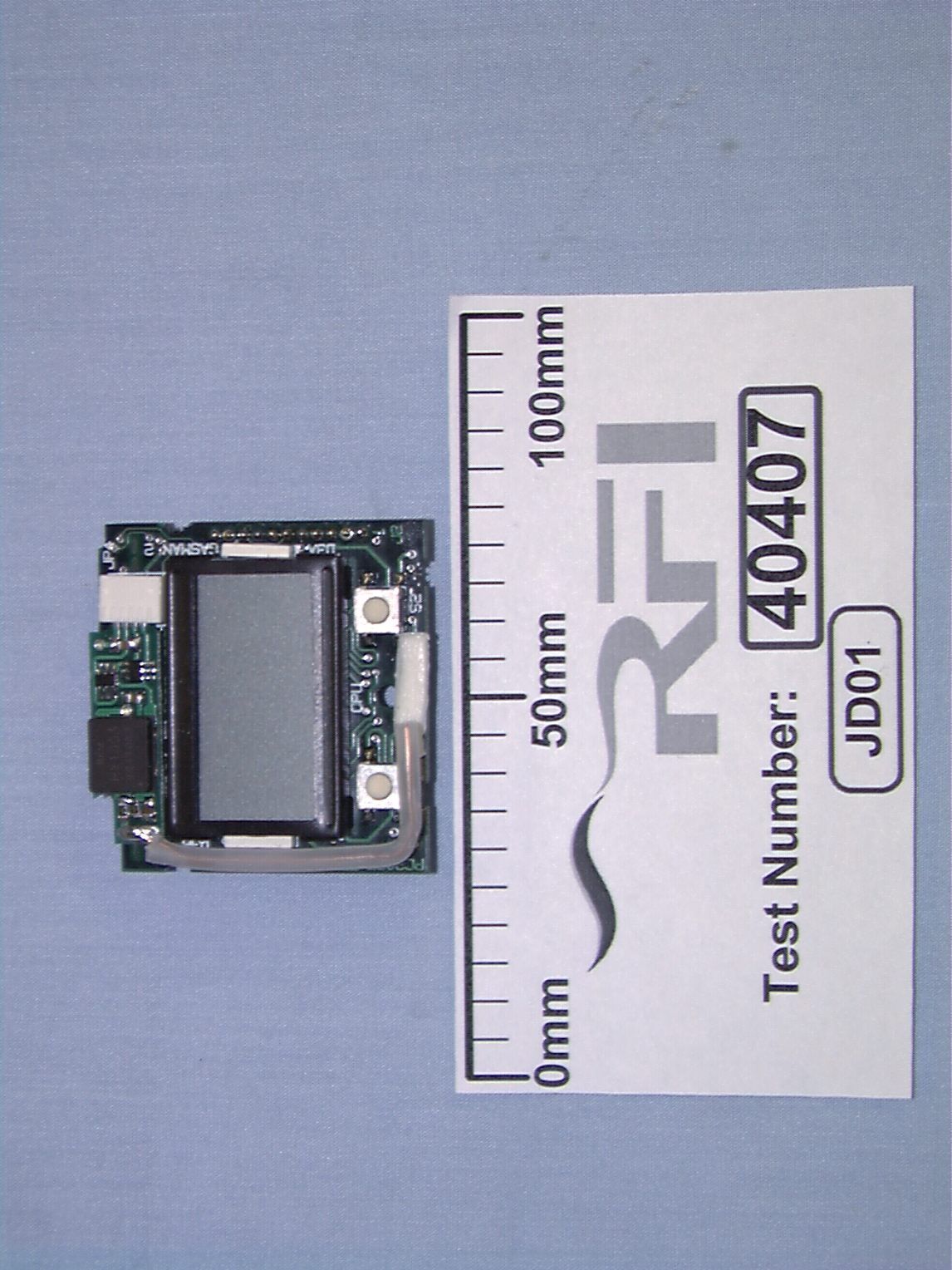
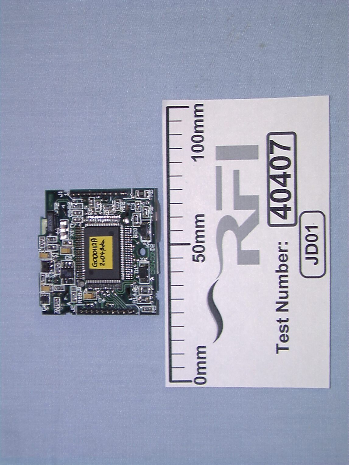

Document Text
Text extracted from the exhibit documents filed with the FCC. Open a document above to read the original.
Users Manual
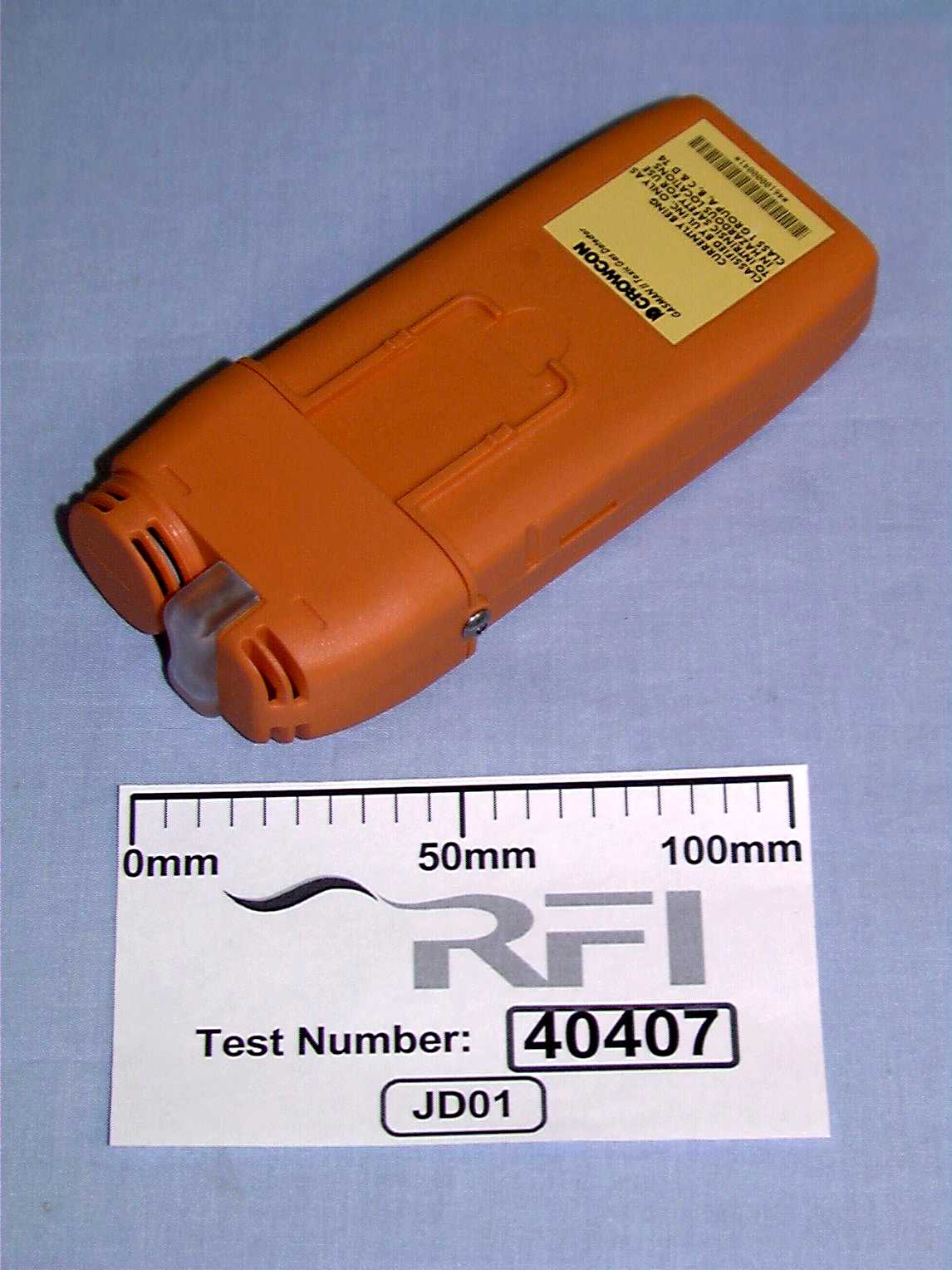
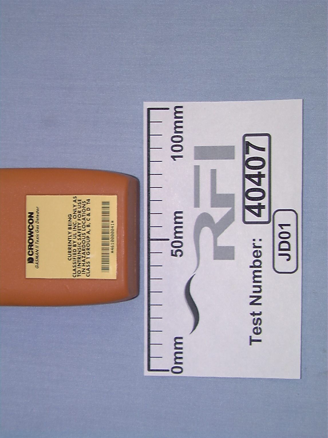
User Manual Addendum Gasman II Portable Gas Detector (This is a draft addendum supplied for content evaluation only) Crowcon Detection Instruments Limited 2 Blacklands Way Abingdon Business Park Abingdon Oxfordshire OX14 1DY United Kingdom Contents ContentsPage 1 IntroductionPage 2 - Determining if the Low-Power Transmitter Option is fitted Page 2 - Preparation for Use Page 2 - Use of a Gasman II fitted with the Low-Power Transmitter option Page 2 OperationPage 2 - Checking the Transmitter Function Page 2 FCC NoticePage 2 1 Introduction This addendum relates to the Low-Power Transmitter option for the Gasman II range of portable gas detectors and should be read in conjunction with the main User Manual, Crowcon document number M07-118. Determining if the Low-Power Transmitter Option is fitted If a Gasman II is fitted with the Low-Power Transmitter option it will be fitted with a label including the words “Complies with FCC part 15,” and “FCC ID number xxx.123” where 'xxx.123' are for example only. It will also have a model/serial number in the range 25009/00001 to 25011/99999. Preparation for Use Use of the device must be in accordance with the recognised standards of the appropriate authority in the company concerned. Prior to use please ensure local regulations and site procedures are followed. Use of a Gasman II fitted with the Low-Power Transmitter option Use is unaffected by the presence of the Low-Power Transmitter option. Operation Checking the Transmitter Function In addition to the checks outlined in the Crowcon instruction manual M07-118, the following check must be made at start- up: The Vibrating Pager Unit should be turned on and its self-test vibration detected to verify its correct operation. The Gasman II transmitter should then be turned on and the vibration detected once again to show the correct operation of the Gasman II transmitter and Vibrating Pager Unit as a system. Failure to carry out this test may result in an alarm condition not being detected by the Vibrating Pager Unit, and hence the vibration version of alarm being unavailable to the user, in the event of gas being detected. FCC Notice This device complies with part 15 of the U.S. Federal Communications Commission (FCC) Rules. Operation is subject to two conditions: (1) this device may not cause harmful interference, and (2) this device must accept any interference received, including interference that may cause undesired operation. NOTE Modifications to the Gasman II fitted with the Low-Power Transmitter option not expressly approved by Crowcon could void the users authority to operate the equipment. 2
ID Label/Location Info
Drawings for Proposed Labels Gasman II Portable Gas Detector Crowcon Detection Instruments Limited 2 Blacklands Way Abingdon Business Park Abingdon Oxfordshire OX14 1DY United Kingdom
ID Label/Location Info
Drawings for Proposed Labels Gasman II Portable Gas Detector Crowcon Detection Instruments Limited 2 Blacklands Way Abingdon Business Park Abingdon Oxfordshire OX14 1DY United Kingdom
Operational Description
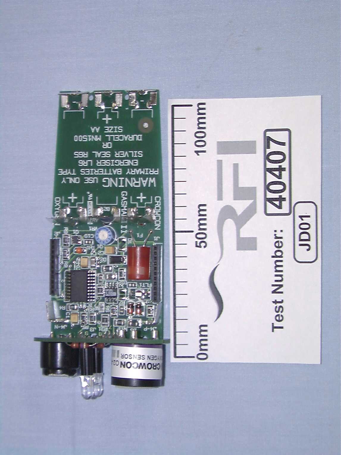
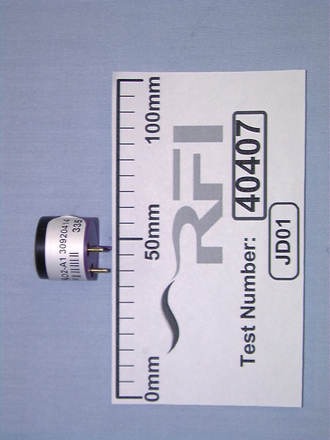
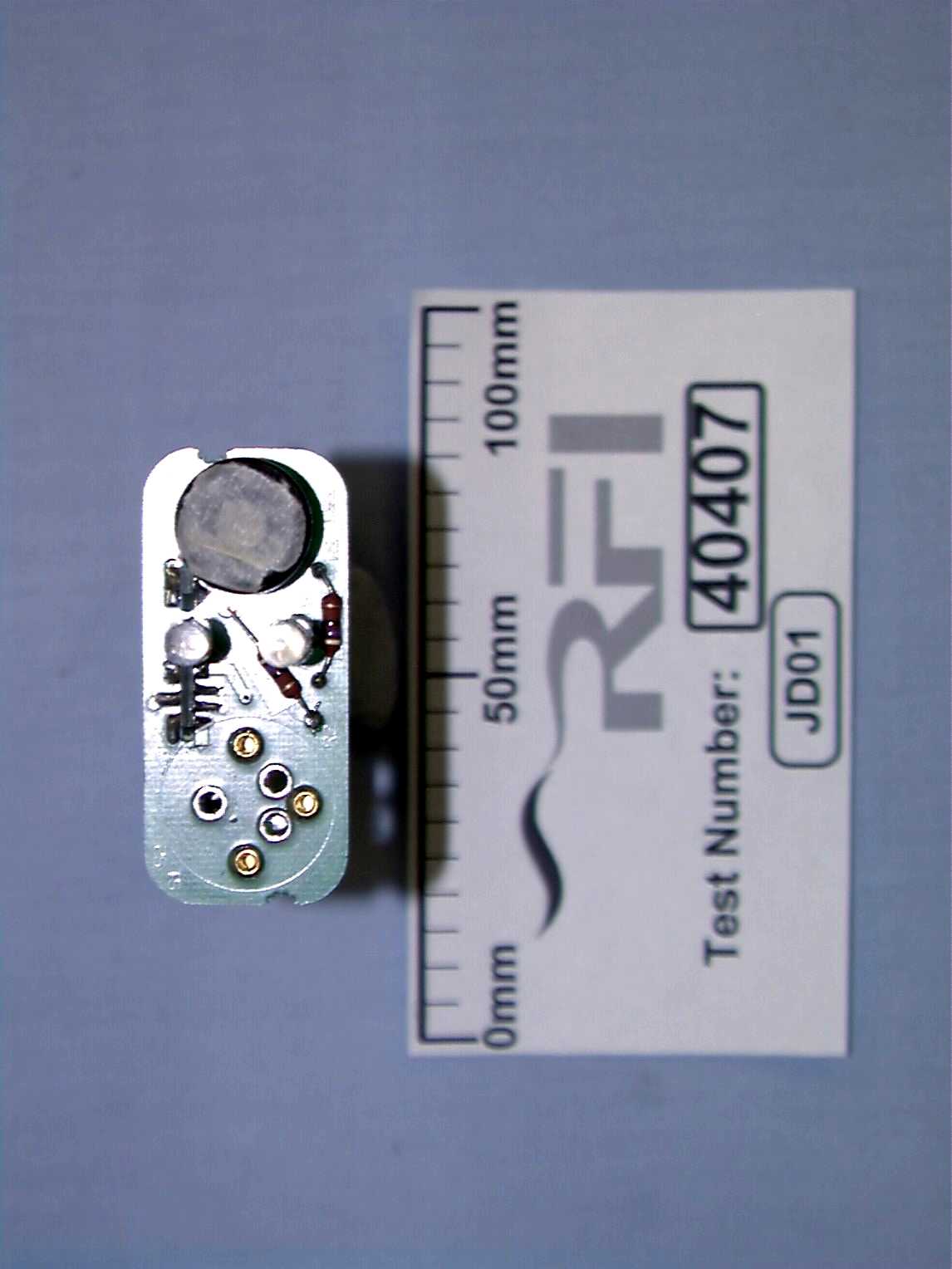
Technical Description Gasman II Portable Gas Detector Crowcon Detection Instruments Limited 2 Blacklands Way Abingdon Business Park Abingdon Oxfordshire OX14 1DY United Kingdom Contents ContentsPage 1 Functional DescriptionPage 2 - System Overview Page 2 - Gasman II Block Diagram Page 2 - Gasman II Circuit Description Page 3 Appendix A - Schematic Diagram (Sheet1)Page 5 Appendix A - Schematic Diagram (Sheet2) - ToxicPage 6 Appendix A - Schematic Diagram (Sheet2) - FlammablePage 7 Appendix A - Schematic Diagram (Sheet2) - OxygenPage 8 Appendix A - Schematic Diagram (Sheet3)Page 9 Appendix A - Schematic Diagram (Sheet4)Page 10 Appendix B - Parts List (Sheet 1)Page 11 Appendix B - Parts List (Sheet 2) - ToxicPage 12 Appendix B - Parts List (Sheet 2) - FlammablePage 13 Appendix B - Parts List (Sheet 2) - OxygenPage 15 Appendix B - Parts List (Sheet 3)Page 16 Appendix B - Parts List (Sheet 4)Page 17 1 Functional Description System Overview The GasmanII Portable Gas Detector system is designed to detect the presence of toxic or flammable gases or the absence of life supporting gases. As an option it may be fitted with a low power transmitter PCB to permit the use of a body-worn Vibrating Pager Unit. The standard GasmanII Portable Gas Detector monitors the level of a particular gas in the atmosphere and provides both an audible and a visual alarm should the gas levels become unacceptable. When fitted with the optional low power transmitter PCB the unit also emits a 418MHz RF carrier wave that is 'On-Off-Key' (OOK) modulated at about 10Hz. It is this signal, which is only emitted while the alarm condition exists, that the GasmanII Vibrating Pager Unit intercepts and produce a pulsing vibration to augment the audible and visual alarms provided by the GasmanII Portable Gas Detector. Gasman II Block Diagram The circuit consists of the functional blocks as shown in Figure 1 below and a complete unit is assembled from 3 PCBs, with an optional fourth PCB, as shown in the appendices. Each of the three distinct gas types requires a specific type of gas sensor, signal conditioning circuitry and calibration information. All of the gas sensors share a similar mechanical design and are plugged into a small daughter board at the top of the unit. The output signal from the various types of sensor is different and each requires a corresponding signal conditioning amplifier to interface the signal to the common CPU section. The calibration information is stored in non-volatile memory within the unit and is factory set. The CPU is powered in a low-power state at all times that batteries are present and controls the electronic switch to apply power to the rest of the circuitry when one of the front-panel mounted buttons is pressed. Once powered the unit continuously monitors the gas level comparing it with preset alarm levels and, should an alarm level be exceeded, the buzzer and the LED operate to provide both audible and visual warnings. The two signals that drive the LEDs are combined on the optional low-power transmitter PCB to form a 10Hz signal that is used to modulate an RF Monolithics transmitter module. Figure 1: Gasman II Block Diagram cpu (ROM & RAM) gas sensor LCD display buzzer LEDs analogue signal conditioning electronic switch low power txmtr (optional) 2 Gasman II Circuit Description The following description of the circuit refers to the schematics shown in Appendix A. Sheet 1 (CPU/Display PCB) The CPU is at the heart of the unit and contains the operating program stored in OTPROM and a quantity of RAM for general variable storage. Q1A and IC3 provide the electronic switch shown in the Block Diagram above and these two components form a switched +3V supply that is used to power various circuit sections. IC2 is an EEPROM and is used to store data relating to configuration and calibration while IC4 provides a CPU reset/watchdog function. Under the control of one of the CPU I/O lines Q1B is used to switch the LCD backlight on and off. S1 and S2, the two user push-buttons, are used to control the units function. Two crystals, X1 and X2, provide the clock signal for the CPU with X1, at 2.51MHz, providing the frequency for normal operation and X2, at approximately 32kHz, providing the clock signal for the CPU when not in full operation. The connections to the Main PCB are made through connectors J1 and J2 with JP4 providing the connection to the optional low-power transmitter PCB. Sheet 2 (Main PCB) - Toxic This PCB contains the 3 batteries used to provide power to the unit, the analogue signal conditioning for the gas sensor and also the 'buffers' for driving the buzzer and the LEDs. IC2 provides the necessary amplification and level shifting to enable the output from the gas sensor to be coupled to the CPU ADC input. The unit is configured using a custom PC application and communication is accomplished via connector J4. IC3 (comparator) is used to extract the data sent by the PC from the common 'signal' wire and Q2 is used to impress the data sent by the Gasman II to the PC onto the 'signal' wire. Varistor, RV1, provides protection against ESD transients. IC3 (op-amp) provides a control loop for powering the sensor and is arranged to maintain constant operating conditions. Header, H1, is a small plug-in PCB containing resistors that set the offset and gain of the sensor signal conditioning amplifier. IC1(A/B) is used to provide a boosted drive signal during an alarm condition for the buzzer and two LEDs. IC1B is wired to provide a differential drive to the buzzer and thus generates a greater sound level. IC1A provides the drive to the LEDs and also the drive to Q2 as mentioned above. Q1 is a depletion-mode FET, i.e. its channel conducts until biased off, which is used to short the sensor terminals when the unit is switched off. The connections to the CPU/Display PCB are made through connectors J1 and J2 while J3 provides the connection to the Sensor PCB. Sheet 2 (Main PCB) - Flammable This PCB contain…
Text truncated - open the document above for the full version.
Operational Description
User Manual Addendum Gasman II Portable Gas Detector (This is a draft addendum supplied for content evaluation only) Crowcon Detection Instruments Limited 2 Blacklands Way Abingdon Business Park Abingdon Oxfordshire OX14 1DY United Kingdom Contents ContentsPage 1 IntroductionPage 2 - Determining if the Low-Power Transmitter Option is fitted Page 2 - Preparation for Use Page 2 - Use of a Gasman II fitted with the Low-Power Transmitter option Page 2 OperationPage 2 - Checking the Transmitter Function Page 2 FCC NoticePage 2 1 Introduction This addendum relates to the Low-Power Transmitter option for the Gasman II range of portable gas detectors and should be read in conjunction with the main User Manual, Crowcon document number M07-118. Determining if the Low-Power Transmitter Option is fitted If a Gasman II is fitted with the Low-Power Transmitter option it will be fitted with a label including the words “Complies with FCC part 15,” and “FCC ID number xxx.123” where 'xxx.123' are for example only. It will also have a model/serial number in the range 25009/00001 to 25011/99999. Preparation for Use Use of the device must be in accordance with the recognised standards of the appropriate authority in the company concerned. Prior to use please ensure local regulations and site procedures are followed. Use of a Gasman II fitted with the Low-Power Transmitter option Use is unaffected by the presence of the Low-Power Transmitter option. Operation Checking the Transmitter Function In addition to the checks outlined in the Crowcon instruction manual M07-118, the following check must be made at start- up: The Vibrating Pager Unit should be turned on and its self-test vibration detected to verify its correct operation. The Gasman II transmitter should then be turned on and the vibration detected once again to show the correct operation of the Gasman II transmitter and Vibrating Pager Unit as a system. Failure to carry out this test may result in an alarm condition not being detected by the Vibrating Pager Unit, and hence the vibration version of alarm being unavailable to the user, in the event of gas being detected. FCC Notice This device complies with part 15 of the U.S. Federal Communications Commission (FCC) Rules. Operation is subject to two conditions: (1) this device may not cause harmful interference, and (2) this device must accept any interference received, including interference that may cause undesired operation. NOTE Modifications to the Gasman II fitted with the Low-Power Transmitter option not expressly approved by Crowcon could void the users authority to operate the equipment. 2
Operational Description
10 July, 2000 Linda Elliott FCC Application Processing Branch Subject: FCC Application Crowcon Detection Instruments Ltd EA97087 Our Ref: lt01\ngc Dear Linda This is to confirm that the model name that sho uld have been put o n the Form 731 is GASMANII and not GASMAN11. Please co uld yo u correct the Form 731. Yo urs si ncer ely Nick Cobb Senior Engineer, RATS Group
Test Report
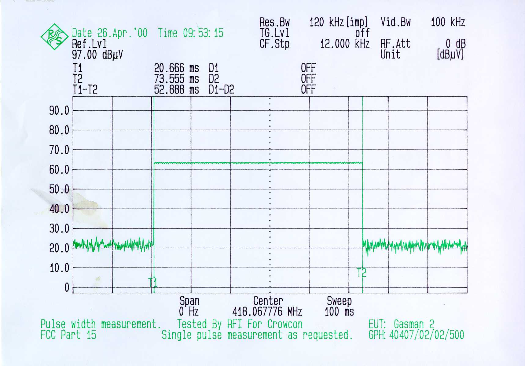
Radio Frequency Investigation Ltd, Ewhurst Park, Ramsdell, Basingstoke, Hampshire, RG26 5RQ, ENGLAND. Tel: +44 (0) 1256 851193 Fax: +44 (0) 1256 851192 Registered in England, No. 211 7901. Registered Office: Ewhurst Park, Ramsdell, Basingstoke, Hampshire RG26 5RQ TESTING 0644 TEST REPORT FROM RADIO FREQUENCY INVESTIGATION LTD. Test Of: Crowcon Detection Instruments Ltd. Gasman 2 To: F.C.C. Part 15 Subpart C: 1998 (Intentional Radiators) Section 15.231 Additional Requirements Only Test Report Serial No: RFI/EMCB1/RP40407C This Test Report Is Issued Under The Authority Of Brian Watson Technical Director: Checked By: Tested By:Release Version No: PDF01 ............................................................................... Issue Date: 25 May 2000Test Date: 12 May 2000 This report is issued in Adobe Acrobat portable document format (PDF). It is only a valid copy of the report if it is being viewed in PDF format with the following security options not allowed: Changing the document, Selecting text and graphics, Adding or changing notes and form fields. Furthermore, the date of creation must match the issue date stated above. This report may be copied in full. RADIO FREQUENCY INVESTIGATION LTD.TEST REPORT S.No: RFI/EMCB1/RP40407C EMC DepartmentPage 2 of 16 Issue Date: 25 May 2000 Test Of:Crowcon Detection Instruments Ltd. Gasman 2 To:F.C.C. Part 15: 1998 Subpart C (Intentional Radiators) Section 15.231 This page has been left intentionally blank. RADIO FREQUENCY INVESTIGATION LTD.TEST REPORT S.No: RFI/EMCB1/RP40407C EMC DepartmentPage 3 of 16 Issue Date: 25 May 2000 Test Of:Crowcon Detection Instruments Ltd. Gasman 2 To:F.C.C. Part 15: 1998 Subpart C (Intentional Radiators) Section 15.231 Table of Contents 1. Client Information......................................................................................................4 2. Equipment Under Test (EUT).....................................................................................5 3. Test Specification, Methods And Procedures..........................................................7 4. Deviations From The Test Specification...................................................................8 5. Operation Of The EUT During Testing......................................................................9 6. Summary Of Test Results........................................................................................10 7. Measurements, Examinations And Derived Results..............................................11 8. Measurement Uncertainty........................................................................................14 Appendix 1. Test Equipment Used...............................................................................15 Appendix 2. Graphical Test Results............................................................................16 RADIO FREQUENCY INVESTIGATION LTD.TEST REPORT S.No: RFI/EMCB1/RP40407C EMC DepartmentPage 4 of 16 Issue Date: 25 May 2000 Test Of:Crowcon Detection Instruments Ltd. Gasman 2 To:F.C.C. Part 15: 1998 Subpart C (Intentional Radiators) Section 15.231 1. Client Information Company Name: Crowcon Detection Instruments Ltd Address: 2 Blacklands Way Abingdon Business Park Abingdon Oxfordshire OX14 1DY Contact Name: Mr P Basham RADIO FREQUENCY INVESTIGATION LTD.TEST REPORT S.No: RFI/EMCB1/RP40407C EMC DepartmentPage 5 of 16 Issue Date: 25 May 2000 Test Of:Crowcon Detection Instruments Ltd. Gasman 2 To:F.C.C. Part 15: 1998 Subpart C (Intentional Radiators) Section 15.231 2. Equipment Under Test (EUT) The client has supplied the following information (with the exception of the Date of Receipt): 2.1. Identification Of Equipment Under Test (EUT) Brand Name: Crowcon Detection Instrument Ltd Model Name or Number: Gasman 2 (Toxic Gas Detector) Unique Type Identification: None stated by client Serial Number: None stated by client Country of Manufacture: UK FCC ID Number: Not applicable Date of Receipt: 12 January 2000 2.2. Description Of EUT The equipment under test is a hand held / body worn gas detector with a low power 418 MHz transmitter. 2.3. Modifications Incorporated In EUT The client has declared that the EUT has not been modified from what is described by the Model Name and Unique Type Identification stated above. RADIO FREQUENCY INVESTIGATION LTD.TEST REPORT S.No: RFI/EMCB1/RP40407C EMC DepartmentPage 6 of 16 Issue Date: 25 May 2000 Test Of:Crowcon Detection Instruments Ltd. Gasman 2 To:F.C.C. Part 15: 1998 Subpart C (Intentional Radiators) Section 15.231 2.4. Additional Information Related To Testing Power Supply Requirement: Internal battery supply of 4.5 V Intended Operating Environment: Light Industry and Heavy Industry Weight: 200 grams Dimensions: 130 mm x 56 mm x 27 mm Interface Ports: None 2.5. Support Equipment No support equipment was used to exercise the EUT during testing. RADIO FREQUENCY INVESTIGATION LTD.TEST REPORT S.No: RFI/EMCB1/RP40407C EMC DepartmentPage 7 of 16 Issue Date: 25 May 2000 Test Of:Crowcon Detection Instruments Ltd. Gasman 2 To:F.C.C. Part 15: 1998 Subpart C (Intentional Radiators) Section 15.231 3. Test Specification, Methods And Procedures 3.1. Test Specification Reference: FCC Part 15 Subpart C:1998 (Intentional Radiators). Section 15.231. (Periodic Operation within the Band 40.66 to 40.70 MHz and above 70 MHz). Additional requirements Only. Title: Code of Federal Regulations, Part 15 (47CFR15) Radio Frequency Devices: Digital Devices. Comments: A description of the test facility used for this test is on file with, and has been accepted by, the Federal Communications Commission as required by Section 2.948 of Federal Rules. Purpose of Test: To determine whether the equipment complied with the requirements of the specification for the purposes of certification. 3.2. Methods And Procedures The methods and procedures used were as detailed in: ANSI C63.2 (1987) Title: American National Standard for Instrumentation - Electromagnetic noise and field strength. AN…
Text truncated - open the document above for the full version.
Contact Information
Applicant
Paul Basham(Mr)
Technical Contact
Radio Frequency Investigation LtdNick Cobb
[email protected]+44 1256 855472
Ewhurst Park, Ramsdell · Hampshire · United Kingdom
Test Firm
RFI Global Services Ltd.Allan Hume
Technical Specifications
| # | Rule Parts | Frequency Range | Power Output |
|---|---|---|---|
| 1 | 15C | 418 MHz - 418 MHz | - |
Other Applications from Crowcon Detection Instruments Ltd
OXOVPU
Apr 10, 2000Vibrating Pager Unit
Equipment Class
CYY - Communications Receiver used w/Pt 15 Transmitter