OXOVPUVibrating Pager Unit
Crowcon Detection Instruments Ltd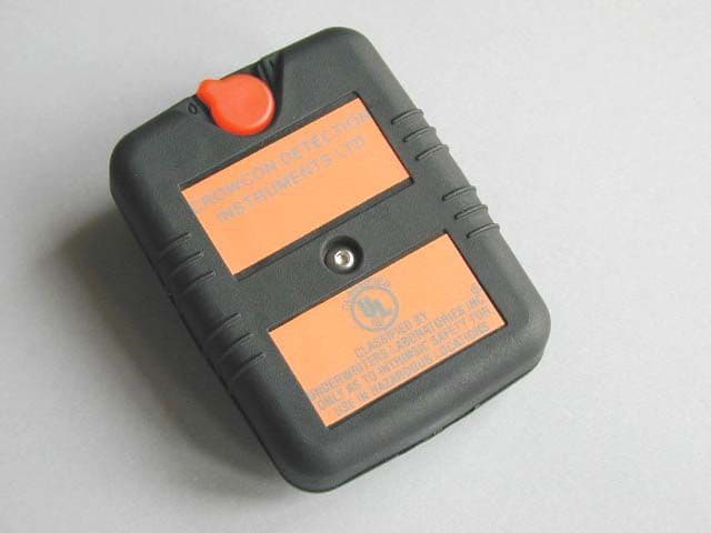
Click to zoom
Application Details
- Equipment Class
- CYY - Communications Receiver used w/Pt 15 Transmitter
- Date of Grant
- Apr 10, 2000
- Application Purpose
- Original Equipment
- Date of Application
- Mar 16, 2000
- Equipment Note
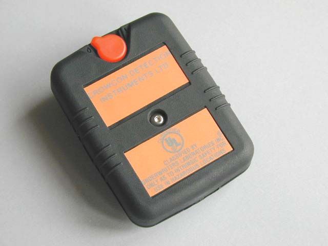
- Vibrating Pager Unit
- Frequency Range
- 418.00000000 - 418.00000000
- Country
- United Kingdom
Documents & Files
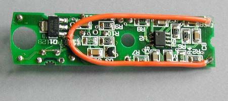
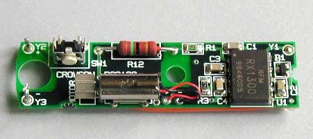
Document Text
Text extracted from the exhibit documents filed with the FCC. Open a document above to read the original.
ID Label/Location Info
Drawings for Proposed Labels Gasman II Vibrating Pager Unit Crowcon Detection Instruments Limited 2 Blacklands Way Abingdon Business Park Abingdon Oxfordshire OX14 1DY United Kingdom
Operational Description
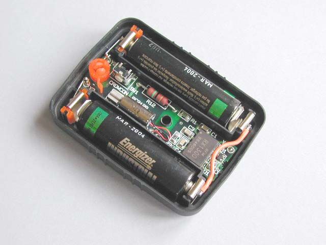
Technical Description Gasman II Vibrating Pager Unit Crowcon Detection Instruments Limited 2 Blacklands Way Abingdon Business Park Abingdon Oxfordshire OX14 1DY United Kingdom Contents ContentsPage 1 Functional DescriptionPage 2 - System Overview Page 2 - Vibrating Pager Block Diagram Page 2 - Vibrating Pager Circuit Description Page 2 Appendix A - Schematic DiagramPage 3 Appendix B - Parts ListPage 4 Page 1 Functional Description System Overview The GasmanII Vibrating Pager Unit is designed to operate in conjunction with a GasmanII Portable Gas Detector fitted with the optional low power transmitter PCB. The standard GasmanII Portable Gas Detector monitors the level of a particular gas, or gases, in the atmosphere and provides both an audible and a visual alarm should the gas levels become unacceptable. When fitted with the optional low power transmitter PCB the unit also emits a 418MHz RF carrier wave that is 'On-Off-Key' (OOK) modulated at about 10Hz. It is this signal, which is only emitted while the alarm condition exists, that the GasmanII Vibrating Pager Unit is designed to intercept and produce a pulsing vibration to augment the audible and visual alarms provided by the GasmanII Portable Gas Detector. Vibrating Pager Block Diagram The circuit consists of the functional blocks as shown in Figure 1 below. The receiver section is provided by a pre- assembled and tested module manufactured by RF Monolithics of Dallas, Texas. The 10Hz signal extracted from the OOK modulation is rectified by the detector stage and used to provide a gating signal to the pulse generator. The vibration motor is thus driven in a slow pulsing fashion to obtain an extra dimension to the vibration the unit produces. Vibrating Pager Circuit Description The following description of the circuit refers to the schematic shown in Appendix A. The receiver function is provided by U1, an RF1300 AM receiver module manufactured by RF Monolithics, which takes its RF input from a short length of wire attached to the underside of the PCB at Y1. Its power supply is de-coupled by R1 and C1 with R1 also providing the current limiting function necessary for I.S. certification. The 10Hz demodulated signal is presented at U1 pin2, the 'base-band output', and has a limited amount of band-pass filtering applied using C3, R3 and C4. The filtered signal is fed back into the comparator stage of U1 which produces, at pin7, a rail-to-rail amplitude square wave form at the modulating frequency. Diode, D1, and capacitors, C5 and C6, provide the detector function and rectify the square-wave form to produce a DC level at their junction. This signal, when above about +1V releases the pulse generator circuit, U2, from its reset state causing it to oscillate at about 1.5Hz. When the unit is switched on the vibration motor is energised for a short while giving reassurance that the batteries are satisfactory. This function is provided by both C5 and C6 which, at closure of the on-off switch, provide a DC level of about 1.5V at their junction for about 1 second. This releases the pulse generator circuit from reset and momentarily energises the vibration motor. The pulse generator function is provided by a low power CMOS 555 timer IC configured as an astable oscillator. The output from the pulse generator stage feeds the motor drive power stage formed from Q1 and its associated components. U3 is included to regulate the voltage applied to the motor during operation and thus maintains a constant 'vibration feel' over a wide range of battery voltage. R7 and R12 provide current limiting in order to satisfy the requirements of Intrinsic Safety. There is no reverse-battery polarity provided as such but the current limiting functions provided by R1, R7 and R12 prevent any damage being done to the unit in the event both batteries are inserted incorrectly. Figure 1: Vibrating Pager Block Diagram receiver 10Hz filter detector pulse generator motor drive M antenna Page 2 Appendix A - Schematic Diagram Page 3 R162R SeeNotes R762R SeeNotes R1215R SeeNotesSeeNotes SW1 B3F-3100 R5220k D1BAV99 C11uF VDD 1 BBO 2 REF 6 THO 5 GND 8 GND 4 DAT 7 CIN 3 GND 9 ANT 10 U1RX1300 Antenna 0V C31uF R20R VSS 1 TRG 2 THD 6 CV 5 VDD 8 RST 4 DIS 7 OUT 3 U2LMC555CM Battery +ve Y2PINY3PIN Battery -ve Q1PZT2222A M1 CO613CL-01L R915k R8180R C10100nF R1162R C9100nF R6470k C61uF R3 24k Y1PIN C21uF C4470nF C51uF C71uF R41M C8100nF R1024k 32 1 U3ZR431 0V C11100nF NOTES:1. Track segments shown between two dotted lines must have 1.5mm creepage & clearance distance.6. Crowcon PCB Number = PC2129.2. Creepage and clearance distance between circuit sections to be 1.5mm.5. Y1-3 should be placed as a 80thou round pad with a 40thou hole.3. Circuit section isolating resistors (R2 and R8) to have 1.5mm creepage distance between pads.4. Current Limiting resistors, R1, R7 and R12 to have 1.5mm creepage and clearance distance around both ends. Appendix B - Parts List This appendix gives the parts list for the GasmanII Vibrating Pager Unit. For each circuit reference a description of the component is given and, where appropriate, its case style is listed. The Farnell order codes are given such that should any further information or clarification be required it may be obtained from them. Circuit Ref.Component DescriptionCase StyleFarnell Code C11uF 16V X7R Multi-layer Ceramic1206499-717 C21uF 16V X7R Multi-layer Ceramic1206499-717 C31uF 16V X7R Multi-layer Ceramic1206499-717 C4470nF 25V X7R Multi-layer Ceramic1206499-705 C51uF 16V X7R Multi-layer Ceramic1206499-717 C61uF 16V X7R Multi-layer Ceramic1206499-717 C71uF 16V X7R Multi-layer Ceramic1206499-717 C8100nF 25V X7R Multi-layer Ceramic1206644-316 C9100nF 25V X7R Multi-layer Ceramic1206644-316 C10100nF 25V X7R Multi-layer Ceramic1206644-316 C11100nF 25V X7R Multi-layer Ceramic1206644-316 D1BAV99SOT23517-021 M1Sanyo CO613CL-01L Vibrator MotorN/AN/A Q1PZT2222A NPN 40V 1.0ASOT223932-875 R162R 0.25W 2% 200ppm Nickel Barrier Resistor1206420-098 R20R 0.25W…
Text truncated - open the document above for the full version.
Operational Description
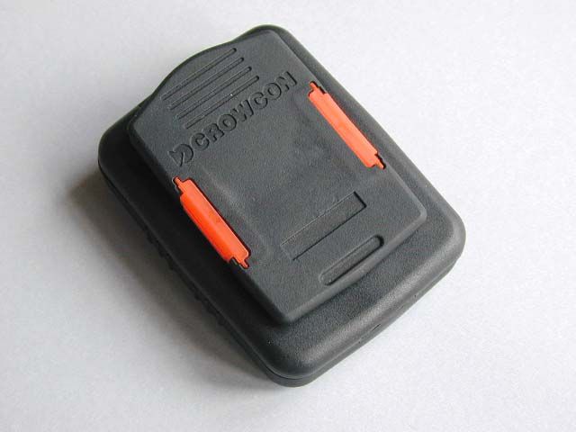
User Manual Vibrating Pager Unit (This is a draft manual supplied for content evaluation only) Crowcon Detection Instruments Limited 2 Blacklands Way Abingdon Business Park Abingdon Oxfordshire OX14 1DY United Kingdom Contents ContentsPage 1 IntroductionPage 2 - Product Overview Page 2 - Preparation for Use Page 2 - Use of the Vibrating Pager Unit Page 2 OperationPage 2 - Warning Page 2 - Checking the Vibrating Pager Unit Function Page 2 - Routine Maintenance Page 2 - Replacement of Batteries Page 2 - To Change the Batteries Page 3 FCC NoticePage 3 SpecificationsPage 3 Page 1 Introduction Product Overview The Vibrating Pager Unit is designed to detect the presence of an alarm signal from a suitably configured portable gas detector and to then initiate a vibration that persists until the portable gas detector exits the alarm condition. Product Description The Vibrating Pager Unit comprises a self-contained electronic circuit, powered by battery, housed inside a purpose built tough plastic container. It is certified to CENELEC and UL intrinsically safe standards, is ingress protected and built from anti-static materials. It is small enough to fit in a hand or pocket, or to clip onto a belt. Preparation for Use The Vibrating Pager Unit is designed and certified for use in Zone 0 areas and can be used in Zone 1, Zone 2, and uncertified areas. The T4 temperature rating limits the areas where the device may be used. Use of the device must be in accordance with the recognised standards of the appropriate authority in the company concerned. For further information please contact Crowcon. Prior to use please ensure local regulations and site procedures are followed. Use of the Vibrating Pager Unit The device may be clipped to a suitable portable gas detector by means of the specifically designed clip. This is designed to slide over the clip of a Gasman II and click positively into place. The device may also be used separated from a suitable portable gas detector by up to 2 metres distance in any orientation. Thus allowing use of the device in the inside pocket of an operator, separate from an externally worn portable gas detector. The device is weatherproof and relatively tough but should not be mistreated. It is suggested that the operator keep the device clean, though it is made from chemically resistant plastic and the stainless steel fixings should not rust. Operation Warning Prior to carrying out any work ensure local regulations and site procedures are followed. Although the device is certified intrinsically safe NEVER attempt to open the enclosure when flammable gas is present. Checking the Vibrating Pager Unit Function Take the device and push the switch from the off position to the on position, standard “1” and “0” symbols are used to denote on and off positions. The device will vibrate for a short period to indicate the motor and motor drive circuitry function, and to show the operator the batteries have not run out of energy. A suitable portable gas detector, eg. a Gasman II from Crowcon incorporating a low-power transmitter, will emit bursts of radio waves immediately after initial switch-on and when an alarm condition is signaled. Thus switching on a suitable portable gas detector within 2 metres of a Vibrating Pager Unit will cause the Vibrating Pager Unit to vibrate, thereby providing a test of both the receiver circuitry and the motor drive function. Routine Maintenance The operation of the Vibrating Pager Unit depends upon the batteries not being flat. It is recommended that the Vibrating Pager Unit be switched off when not in use. When in normal use with few infrequent alarms to report, the battery life should exceed 6 months when operated for 8 hours per day. If many alarms are reported the battery life may be expected to drop. The Vibrating Accessory should not be held under water, as there is a risk the device will fill with water thereby hampering operation. Replacement of Batteries The Vibrating Pager Unit has been certified for use with 2 AA disposable batteries. 2 types are permitted: Duracell, and alkaline Ever-ready. Other battery makes or types are not permitted, as the product is not certified for use in hazardous areas when fitted with alternatives. If an operator is unsure about the battery types allowed, then they should contact Crowcon. Page 2 To Change the Batteries: • Turn the device off. • Open the enclosure in a safe area by unscrewing the hex head screw using a M3 Allen key. • Remove the two batteries. • Replace them with 2 new batteries of a recommended type. • Re-assemble the device and tighten the screw. • Turn the device on and check it vibrates. FCC Notice This device complies with Part 15 of the U.S. Federal Communications Commission (FCC) Rules. Operation is subject to the following two conditions: (1) this device may not cause harmful interference, and (2) this device must accept any interference received, including interference that may cause undesired operation. NOTE Any changes or modifications not expressly approved by Crowcon could void the users authority to operate this device. Specifications Dimensions:56 x 74 x 20 mm including the clip 2.2 x 2.9 x 0.8 inches including the clip Weight:100 grams including the batteries Operating temperature:-10 to +50 °C 14 to 122 °F Ingress Protection:IP66 Safety Protection:Intrinsically Safe Approval Code:EEx ia IIC T4 Div 1 Class 1 Groups A B C D Zones:0 1 2 Page 3
Test Report
Radio Frequency Investigation Ltd, Ewhurst Park, Ramsdell, Basingstoke, Hampshire, RG26 5RQ, ENGLAND. Tel: +44 (0) 1256 851193 Fax: +44 (0) 1256 851192 Registered in England, No. 211 7901. Registered Office: Ewhurst Park, Ramsdell, Basingstoke, Hampshire RG26 5RQ TESTING 0644 TEST REPORT FROM RADIO FREQUENCY INVESTIGATION LTD. Test Of: Crowcon Detection Instruments Ltd. Vibrating Pager Unit To: FCC Part 15: 1998 Class B Test Report Serial No: RFI/EMCB1/RP40407A This Test Report Is Issued Under The Authority Of Brian Watson Technical Director: Checked By: Tested By:Release Version No: PDF01 Issue Date: 4 February 2000Test Date: 12 January 2000 This report is issued in Adobe Acrobat portable document format (PDF). It is only a valid copy of the report if it is being viewed in PDF format with the following security options not allowed: Changing the document, Selecting text and graphics, Adding or changing notes and form fields. Furthermore, the date of creation must match the issue date stated above. This report may be copied in full. RADIO FREQUENCY INVESTIGATION LTD.TEST REPORT S.No: RFI/EMCB1/RP40407A EMC DepartmentPage 2 of 22 Issue Date: 4 February 2000 Test Of:Crowcon Detection Instruments Ltd. Vibrating Pager Unit To:F.C.C. Part 15: 1998 Class B This page has been left intentionally blank. RADIO FREQUENCY INVESTIGATION LTD.TEST REPORT S.No: RFI/EMCB1/RP40407A EMC DepartmentPage 3 of 22 Issue Date: 4 February 2000 Test Of:Crowcon Detection Instruments Ltd. Vibrating Pager Unit To:F.C.C. Part 15: 1998 Class B Table of Contents 1. Client Information......................................................................................................4 2. Equipment Under Test (EUT).....................................................................................5 3. Test Specification, Methods And Procedures..........................................................6 4. Deviations From The Test Specification...................................................................7 5. Operation Of The EUT During Testing......................................................................8 6. Summary Of Test Results..........................................................................................9 7. Measurements, Examinations And Derived Results..............................................10 8. Measurement Uncertainty........................................................................................13 Appendix 1. Test Equipment Used...............................................................................14 Appendix 2. Measurement Methods............................................................................15 Appendix 3. Test Configuration Drawings..................................................................17 Appendix 4. Graphical Test Results............................................................................20 Appendix 5. Photographs of EUT.................................................................................21 RADIO FREQUENCY INVESTIGATION LTD.TEST REPORT S.No: RFI/EMCB1/RP40407A EMC DepartmentPage 4 of 22 Issue Date: 4 February 2000 Test Of:Crowcon Detection Instruments Ltd. Vibrating Pager Unit To:F.C.C. Part 15: 1998 Class B 1. Client Information Company Name: Crowcon Detection Instruments Ltd Address: 2 Blacklands Way Abingdon Business Park Abingdon Oxfordshire OX14 1DY Contact Name: Mr P Basham RADIO FREQUENCY INVESTIGATION LTD.TEST REPORT S.No: RFI/EMCB1/RP40407A EMC DepartmentPage 5 of 22 Issue Date: 4 February 2000 Test Of:Crowcon Detection Instruments Ltd. Vibrating Pager Unit To:F.C.C. Part 15: 1998 Class B 2. Equipment Under Test (EUT) The following information (with the exception of the Date of Receipt) has been supplied by the client: 2.1. Identification Of Equipment Under Test (EUT) Brand Name: Crowcon Detection Instruments Ltd Model Name or Number: Vibrating Pager Unit Unique Type Identification: None stated by client Serial Number: None stated by client Country of Manufacture: UK FCC ID Number: Not applicable Date of Receipt: 12 January 2000 2.2. Description Of EUT The equipment under test was a hand held / body worn vibrating pager. 2.3. Modifications Incorporated In EUT The client has declared that the EUT has not been modified from what is described by the Model Name and Unique Type Identification stated above. 2.4. Additional Information Related To Testing Power Supply Requirement: Internal battery supply of 3 V Intended Operating Environment: Light Industry and Heavy Industry Weight: 80 grams Dimensions: 75 x 55 x 20mm Interface Ports: None 2.5. Support Equipment No support equipment was used to exercise the EUT during testing. RADIO FREQUENCY INVESTIGATION LTD.TEST REPORT S.No: RFI/EMCB1/RP40407A EMC DepartmentPage 6 of 22 Issue Date: 4 February 2000 Test Of:Crowcon Detection Instruments Ltd. Vibrating Pager Unit To:F.C.C. Part 15: 1998 Class B 3. Test Specification, Methods And Procedures 3.1. Test Specification Reference: FCC Part 15: 1998 Class B Title: Code of Federal Regulations, Part 15 (47CFR15) Radio Frequency Devices: Digital Devices. Comments: A description of the test facility used for this test is on file with, and has been accepted by, the Federal Communications Commission as required by Section 2.948 of Federal Rules. Purpose of Test: To determine whether the equipment complied with the requirements of the specification for the purposes of certification. 3.2. Methods And Procedures The methods and procedures used were as detailed in: ANSI C63.2 (1987) Title: American National Standard for Instrumentation - Electromagnetic noise and field strength. ANSI C63.4 (1992) Title: American National Standard Methods of Measurement of Electromagnetic Emissions from Low Voltage Electrical and Electronic Equipment in the Range of 9 kHz to 40 GHz. ANSI C63.5 (1988) Title: American National Standard for the Calibration of antennas used for Radiated Emission measurements in Electromagnetic Interference (EMI) control. ANS…
Text truncated - open the document above for the full version.
Contact Information
Applicant
Paul Basham(Mr)
Technical Contact
Radio Frequency Investigation LtdNick Cobb
[email protected]+44 1256 855472
Ewhurst Park, Ramsdell · Hampshire · United Kingdom
Technical Specifications
| # | Rule Parts | Frequency Range | Power Output |
|---|---|---|---|
| 1 | 15B | 418 MHz - 418 MHz | - |
Other Applications from Crowcon Detection Instruments Ltd
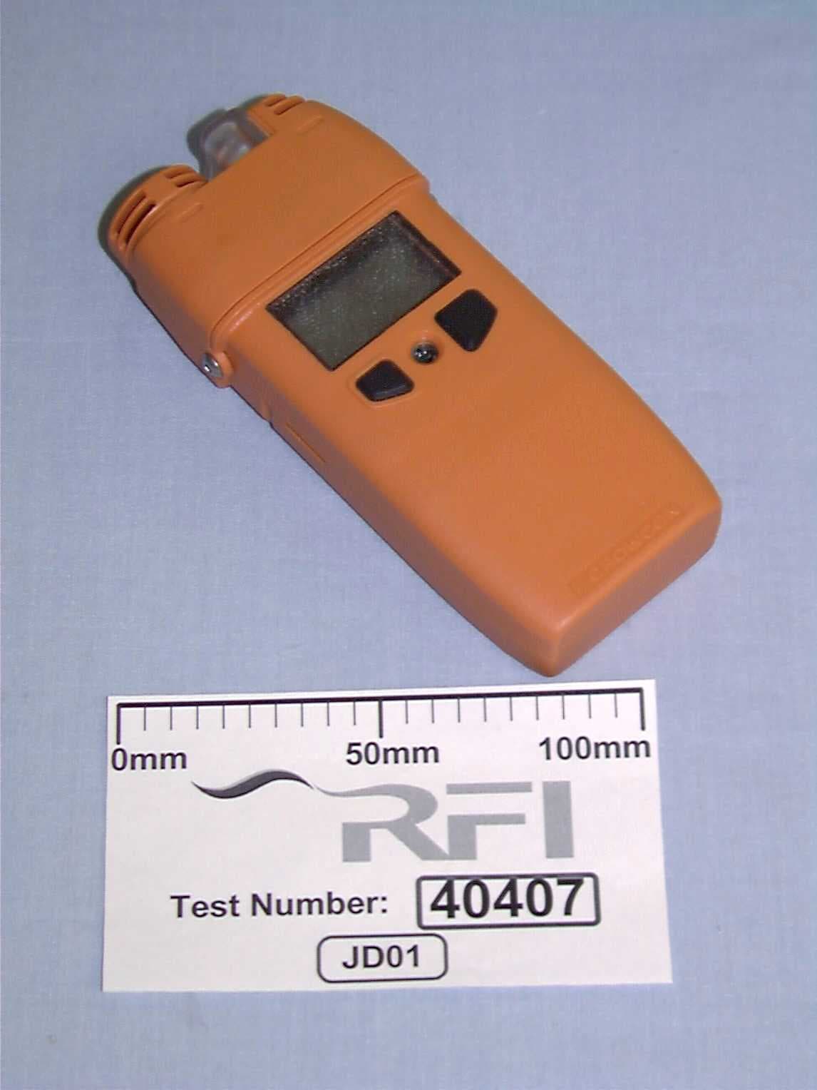
OXOGASMANII
Jul 26, 2000Gasman 11 Portable Gas Detector
Equipment Class
DXX - Part 15 Low Power Communication Device Transmitter