OXW-DS0028WiFi Gateway
Device Solutions Inc.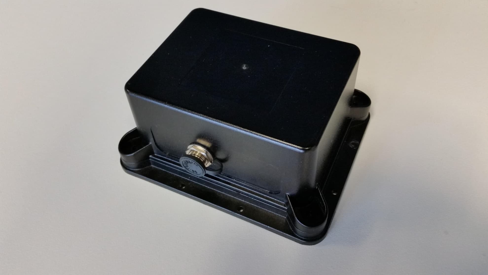
Click to zoom
Application Details
- Equipment Class
- DTS - Digital Transmission System
- Date of Grant
- Feb 09, 2015
- Application Purpose
- Original Equipment
- Date of Application
- Feb 09, 2015
- Equipment Note
- WiFi Gateway
- Frequency Range
- 2412.00000000 - 2462.00000000
- Company
- Device Solutions Inc.
- Country
- United States
Documents & Files
Document Text
Text extracted from the exhibit documents filed with the FCC. Open a document above to read the original.
Users Manual
Device Solutions Gateway & Sensor Installation Instructions 1 FCC Interference Statement Changes or modifications not expressly approved by Device Solutions could void the user’s authority to operate this equipment. Note: This equipment has been tested and found to comply with the limits for a Class B digital device, pursuant to part 15 of the FCC Rules. These limits are designed to provide reasonable protection against harmful interference in a residential installation. This equipment generates, uses and can radiate radio frequency energy and, if not installed and used in accordance with the instructions, may cause harmful interference to radio communications. However, there is no guarantee that interference will not occur in a particular installation. If this equipment does cause harmful interference to radio or television reception, which can be determined by turning the equipment off and on, the user is encouraged to try to correct the interference by one or more of the following measures: • Reorient or relocate the receiving antenna. • Increase the separation between the equipment and receiver. • Connect the equipment into an outlet on a circuit different from that to which the receiver is connected. • Consult the dealer or an experienced radio/TV technician for help. This device complies with Part 15 of the FCC Rules. Operation is subject to the following two conditions: (1) This device may not cause harmful interference, and (2) this device must accept any interference received, including interference that may cause undesired operation. This Class B digital apparatus complies with Canadian ICES-003. 2 Cellular Gateway Installation 1. Using a Torx T10 driver, remove the four 3/8” #4 screws into the corners of the enclosure top that fasten it to the enclosure base. 2. Connect the battery. 3. Reinstall the four 3/8” #4 screws into the corners of the enclosure top that fasten it to the enclosure base. The screws must be tightened to a torque of 8.2 +/-0.5 kgf-cm to ensure that the IP68 rating is maintained. 4. Attach the enclosure to a surface. The best RF performance is obtained by mounting the Gateway to a vertical service. 5. Insert the external power plug into the jack and tighten the locking ring. Failure to properly tighten the locking ring will invalidate the IP68 rating of the Gateway. 3 WiFi Gateway Installation 1. Using a Torx T10 driver, remove the four 3/8” #4 screws into the corners of the enclosure top that fasten it to the enclosure base. 2. Connect the battery. 3. Press the button on the Gateway, the green LED will illuminate. 4. The Gateway has become a WiFi Access Point. Using a laptop or similar device connect to the “DS-Cellio” network. This is an unsecured connection and does not require a password. 5. Browse to 192.168.10.1. 6. Locate the desired system and press the Join button. 7. If required, enter the password for the WiFi Access Point 8. Reinstall the four 3/8” #4 screws into the corners of the enclosure top that fasten it to the enclosure base. The screws must be tightened to a torque of 8.2 +/-0.5 kgf-cm to ensure that the IP68 rating is maintained. 9. Attach the enclosure to a surface. The best RF performance is obtained by mounting the Gateway to a vertical service. 10. Insert the external power plug into the jack and tighten the locking ring. Failure to properly tighten the locking ring will invalidate the IP68 rating of the Gateway. 4 Sensor Installation 1. Use a Torx T10 driver to remove the screws that hold the top of the Sensor's enclosure to the baseplate. 2. Verify the signal strength at the Sensor. Note: This signal strength monitoring process may only be executed on one Sensor at a time. a. Open the Gateway by using a Torx T10 bit to remove the four screws which hold the enclosure top to the base plate. b. Press the button on the Gateway to enter "Range Check Mode". c. Wait for the internal green LED to illuminate. d. Place the Sensor within 50 feet line of sight of the Gateway e. Reboot the Sensor by removing and re-installing the 9 volt battery f. Wait for the Sensor's internal LED to illuminate (up to 10 seconds) g. The color of the LED indicates the following (red – poor signal quality, yellow – marginal signal quality, green – good signal quality) h. Move the Gateway and/or Sensor until the Sensor displays a good signal condition for at least 5 consecutive seconds. i. Repeat c through g for each sensor. j. Disable "Range Check Mode" for the Gateway by pressing the button on the Gateway again (if this step is forgotten the Gateway will exit Range Check Mode in one hour) k. Turn off each Sensor by removing the 9 volt battery (if this step is forgotten the sensor will exit install mode in five minutes) 3. Strip the insulation from the end of transducer wires. 4. Tin the ends of the transducer cable with a soldering iron. 5. Trim the transducer wire such that only 0.25 inches remains uninsulated. 6. Inspect the transducer cable for loose solder and wire strands. Repeat steps 3 through 6 if found. Loose solder or wire strands can cause permanent damage to the Sensor and/or transducer. 7. Remove the battery from the Sensor. Performing the following steps with the battery installed can lead to permanent damage of the device. 8. Loosen the nut from the outside of the cable restraint shown above. 9. Pass the transducer wires through the cable restraint. 10. Tighten the cable restraint nut to the cable restraint. Note: The transducer cable must be between 2.9 and 6.4 mm in diameter and must be tighten to a torque of 25-30 inch lbs to avoid water infiltration. 11. Attach the transducer wires to the terminal blocks. This connection depends on the type of transducer used. 12. Install the 9 volt battery in the sensor 13. Re-install the screws that hold the top of the enclosure to the baseplate. 14. Attach the enclosure to a surface. The best RF performance is obtained by mounting the Sensor vertically.
External Photos
OXW-DS0028 External Label location WiFi Module – External Photo
ID Label/Location Info
Bottom Housing, P13 M-HSG211-PA1 50.8MM – 0.2 (2”-0.0078) Part no.: DS0028 WiFi Gateway Designed In USA Contains: FCC ID: OXW-DS0028 This device complies with Part 15 of the FCC Rules. Operation is subject to the following two conditions: (1) this device may not cause harmful interference, and (2) this device must accept any interference received, including interference that may cause undesired operation. 50.8MM – 0.2 (2”-0.0078) Box size 23x10mm R0.5 Excluded the black line Leave blank Made in Malaysia 6V 2A Note: ① DS part code DO0038 ② Size 50.80MM X 50.80MM ( RADIUS : 3MM X 4 CORNERS ) ③ Printing : 1 COLOR (black) ④ Packing : ROLL FORM ⑤ Materials : Avery Tamper Proof metalized alum processed label TE Matt50 VOID PAT1 8LK, PE Lamination Label, FCC ID2 ,Collector P13-20-0011-1
Internal Photos
OXW-DS0028 Internal WiFi Module – Internal Photo OXW-DS0028 900MHz Radio Board (PA0002) OXW-DS0028 Board Stack Bottom View OXW-DS0028 WiFi Board (PA0021)
RF Exposure Info
FCC ID: OXW-DS0028 MAXIMUM PERMISSIBLE EXPOSURE (MPE) DATA REPORT Reviewed by: Quality Manager Test Report S/N: Test Dates: EUT Type: Page 1 of 7 0Y1412312385.OXW 01/23/2015 WiFi Gateway © 2015 PCTEST Engineering Laboratory, Inc. REV 3.2MPE 7/27/2012 Applicant Name: Date of Testing: Device Solutions Inc. 01/23/2015 3211 Moorefields Road Test Site/Location: Hillsborough, NC 27278 PCTEST Lab, Columbia, MD, USA United States Test Report Serial No.: 0Y1412312385.OXW FCC ID: OXW-DS0028 APPLICANT: Device Solutions Inc. EUT Type: WiFi Gateway FCC Rule Part(s): FCC Part 1 (§1.1310) and Part 2 (§2.1091) FCC Classifications: FCC Part 15 Frequency Hopping Spread Spectrum Transceiver (DSS) Digital Transmission System (DTS) Test Procedure: OET Bulletin 65 The device bearing the FCC Identifier specified above has been shown to comply with the applicable technical standards as indicated in the measurement report and has been tested in accordance with the measurement procedures specified in FCC OET Bulletin 65 (See Test Report). These measurements were performed with no deviation from the standards. Test results reported herein relate only to the item(s) tested. I authorize and attest to the accuracy of data. All measurements reported herein were performed by me or were made under my supervision and are correct to the best of my knowledge and belief. I assume full responsibility for the completeness of these measurements and vouch for the qualifications of all persons taking them. PCTEST ENGINEERING LABORATORY, INC. 6660-B Dobbin Road, Columbia, MD 21045 USA Tel. 410.290.6652 / Fax 410.290.6554 http://www.pctestlab.com RF EXPOSURE EVALUATION Maximum Permissible Exposure (MPE) FCC ID: OXW-DS0028 MAXIMUM PERMISSIBLE EXPOSURE (MPE) DATA REPORT Reviewed by: Quality Manager Test Report S/N: Test Dates: EUT Type: Page 2 of 7 0Y1412312385.OXW 01/23/2015 WiFi Gateway © 2015 PCTEST Engineering Laboratory, Inc. REV 3.2MPE 7/27/2012 T A B L E O F C O N T E N T S 1.0 RF EXPOSURE EVALUATION – MAXIMUM PERMISSIBLE EXPOSURE (MPE) ......................... 3 1.1 INTRODUCTION ................................................................................................................................... 3 1.2 EUT DESCRIPTION .............................................................................................................................. 3 1.3 MPE REQUIREMENTS OVERVIEW ..................................................................................................... 4 1.4 PROCEDURE ........................................................................................................................................ 5 1.5 SUMMARY OF RESULTS ..................................................................................................................... 6 2.0 CONCLUSION .................................................................................................................................. 7 FCC ID: OXW-DS0028 MAXIMUM PERMISSIBLE EXPOSURE (MPE) DATA REPORT Reviewed by: Quality Manager Test Report S/N: Test Dates: EUT Type: Page 3 of 7 0Y1412312385.OXW 01/23/2015 WiFi Gateway © 2015 PCTEST Engineering Laboratory, Inc. REV 3.2MPE 7/27/2012 1 . 0 R F E X P O S U R E E V A L U A T IO N – M A X I M U M P E R M I S S I B L E E X P O S U R E ( M P E ) 1.1 Introduction This document is prepared on behalf of Device Solutions Inc. to show compliance with the RF Exposure requirements as required in §1.1310 of the FCC Rules and Regulations and RSS-102 of Industry Canada. The limit for Maximum Permissible Exposure (MPE), specified in FCC §1.1310, is listed in Table 1-1. According to FCC §1.1310 and RSS-102: the criteria listed in the following table shall be used to evaluate the environmental impact of human exposure to radio-frequency (RF) radiation as specified in §1.1307(b). Frequency Range (MHz) Electric Field Strength (V/m) Magnetic Field Strength (A/m) Power Density (mW/cm 2 ) Average Time (Minutes) (A) Limits For Occupational / Control Exposures (f = frequency) 30-300 61.4 0.163 1.0 6 300-1500 ... ... f/300 6 1500-100,000 ... ... 5.0 6 (B) Limits For General Population / Uncontrolled Exposure (f = frequency) 30-300 27.5 0.073 0.2 30 300-1500 ... ... f/1500 30 1500-100,000 ... ... 1.0 30 Table 1-1. Limits for Maximum Permissible Exposure (MPE) 1.2 EUT Description The Device Solutions Model: DS0028 is a WiFi Gateway containing the 900MHz ISM Band Sensor Board Module FCC ID: OXW-PA0002 and 2.4GHz 802.11 Type WiFi Module FCC ID: O7P-362. For this MPE evaluation, the device is set to transmit from the antenna of each transmitter and the RF exposure of each transmitter is evaluated individually. EUT: Model: DS0028 Grantee: Device Solutions Inc. FCC ID: OXW-DS0028 Antennas: Please see technical description for list of available antenna options FCC ID: OXW-DS0028 MAXIMUM PERMISSIBLE EXPOSURE (MPE) DATA REPORT Reviewed by: Quality Manager Test Report S/N: Test Dates: EUT Type: Page 4 of 7 0Y1412312385.OXW 01/23/2015 WiFi Gateway © 2015 PCTEST Engineering Laboratory, Inc. REV 3.2MPE 7/27/2012 1.3 MPE Requirements Overview Three different categories of transmitters are defined by the FCC in OET Bulletin 65. These categories are fixed installation, mobile, and portable and are defined as follows: o Fixed Installations: fixed location means that the device, including its antenna, is physically secured at a permanent location and is not able to be easily moved to another location. Additionally, distance to humans from the antenna is maintained to at least 2 meters. o Mobile Devices: a mobile device is defined as a transmitting device designed to be used in other than fixed locations and to be generally used in such a way that a separation distance of at least 20 centimeters is normally maintained between the transmitter's radiating structures and the body of the user or nearby persons. Transmitters designed to be used by consumers or workers that can be easily re-located, such as a wireless modem operating in a …
Text truncated - open the document above for the full version.
Test Report
FCC ID: OXW-DS0028 FCC Pt. 15.247 802.11b/g/n MEASUREMENT REPORT (CERTIFICATION) Reviewed by: Quality Manager Test Report S/N: Test Dates: EUT Type: Page 1 of 22 0Y1412312386.OXW 12/22/2014 - 01/23/2015 WiFi Gateway © 2015 PCTEST Engineering Laboratory, Inc. V 1.31 11/19/2014 Applicant Name: Date of Testing: Device Solutions 12/22/2014 - 01/23/2015 3211 Moorefields Road Test Site/Location: Hillsborough, NC 27278 PCTEST Lab, Columbia, MD, USA United States Test Report Serial No.: 0Y1412312386.OXW FCC ID: OXW-DS0028 APPLICANT: Device Solutions Application Type: Certification Model(s): DS0028 EUT Type: WiFi Gateway FCC Classification: Digital Transmission System (DTS) FCC Rule Part(s): Part 15.247 Test Procedure(s): KDB 558074 v03r02 This equipment has been shown to be capable of compliance with the applicable technical standards as indicated in the measurement report and was tested in accordance with the measurement procedures specified in KDB 558074 v03r02. Test results reported herein relate only to the item(s) tested. I attest to the accuracy of data. All measurements reported herein were performed by me or were made under my supervision and are correct to the best of my knowledge and belief. I assume full responsibility for the completeness of these measurements and vouch for the qualifications of all persons taking them. PCTEST ENGINEERING LABORATORY, INC. 7185 Oakland Mills Road, Columbia, MD 21046 USA Tel. 410.290.6652 / Fax 410.290.6654 http://www.pctestlab.com MEASUREMENT REPORT FCC Part 15.247 WLAN 802.11b/g/n FCC ID: OXW-DS0028 FCC Pt. 15.247 802.11b/g/n MEASUREMENT REPORT (CERTIFICATION) Reviewed by: Quality Manager Test Report S/N: Test Dates: EUT Type: Page 2 of 22 0Y1412312386.OXW 12/22/2014 - 01/23/2015 WiFi Gateway © 2015 PCTEST Engineering Laboratory, Inc. V 1.31 11/19/2014 TABLE OF CONTENTS FCC PART 15.247 MEASUREMENT REPORT .................................................................................................. 3 1.0 INTRODUCTION ...................................................................................................................................... 4 1.1 SCOPE ........................................................................................................................................................... 4 1.2 PCTEST TEST LOCATION ............................................................................................................................ 4 2.0 PRODUCT INFORMATION ..................................................................................................................... 5 2.1 EQUIPMENT DESCRIPTION......................................................................................................................... 5 2.2 DEVICE CAPABILITIES ................................................................................................................................. 5 2.3 TEST CONFIGURATION ............................................................................................................................... 5 2.4 EMI SUPPRESSION DEVICE(S)/MODIFICATIONS ...................................................................................... 5 3.0 DESCRIPTION OF TEST ........................................................................................................................ 6 3.1 EVALUATION PROCEDURE ......................................................................................................................... 6 3.2 AC LINE CONDUCTED EMISSIONS ............................................................................................................. 6 3.3 RADIATED EMISSIONS ................................................................................................................................ 7 3.4 ENVIRONMENTAL CONDITIONS ................................................................................................................. 7 4.0 ANTENNA REQUIREMENTS .................................................................................................................. 8 5.0 TEST EQUIPMENT CALIBRATION DATA .............................................................................................. 9 6.0 TEST RESULTS .................................................................................................................................... 10 6.1 SUMMARY ................................................................................................................................................... 10 6.2 RADIATED SPURIOUS EMISSION MEASUREMENTS .............................................................................. 11 6.3 RADIATED RESTRICTED BAND EDGE MEASUREMENTS ...................................................................... 16 6.4 LINE-CONDUCTED TEST DATA ................................................................................................................. 20 7.0 CONCLUSION ....................................................................................................................................... 22 FCC ID: OXW-DS0028 FCC Pt. 15.247 802.11b/g/n MEASUREMENT REPORT (CERTIFICATION) Reviewed by: Quality Manager Test Report S/N: Test Dates: EUT Type: Page 3 of 22 0Y1412312386.OXW 12/22/2014 - 01/23/2015 WiFi Gateway © 2015 PCTEST Engineering Laboratory, Inc. V 1.31 11/19/2014 MEASUREMENT REPORT FCC Part 15.247 § 2.1033 General Information APPLICANT: Device Solutions APPLICANT ADDRESS: 3211 Moorefields Road Hillsborough, NC 27278, United States TEST SITE: PCTEST ENGINEERING LABORATORY, INC. TEST SITE ADDRESS: 7185 Oakland Mills Road, Columbia, MD 21046 USA FCC RULE PART(S): Part 15.247 BASE MODEL: DS0028 FCC ID: OXW-DS0028 FCC CLASSIFICATION: Digital Transmission System (DTS) Test Device Serial No.: FCC1, FCC2 Production Pre-Production Engineering DATE(S) OF TEST: 12/22/2014 - 01/23/2015 TEST REPORT S/N: 0Y1412312386.OXW Test Facility / Accreditations Measurements were performed at PCTEST Engineering Lab located in Columbia, M…
Text truncated - open the document above for the full version.
Test Report
Application For Title 47 USC, Part 2, Subpart J, Paragraph 2.902, Equipment Authorization of Verification for an Unintentional Radiator per Part 15, Subpart B, Paragraphs 15.107 and 15.109 And Part 2, Subpart J, Paragraph 2.907 Equipment Authorization of Certification for an Intentional Radiator per Part 15, Subpart C, paragraph 15.247 For the Inventek Systems Models: ISM43362-M3G-L44-E and ISM43362-M3G-L44-U FCC ID: O7P-362 IC: 10147A-362 UST Project: 13-0186 Issue Date: July 29, 2013 Total Pages: 122 3505 Francis Circle Alpharetta, GA 30004 PH: 770-740-0717 Fax: 770-740-1508 www.ustech-lab.com I certify that I am authorized to sign for the Test Agency and that all of the statements in this report and in the Exhibits attached hereto are true and correct to the best of my knowledge and belief: US TECH (Agent Responsible For Test): By: Alan Ghasiani Name: Title: Compliance Engineer – President Date: July 25, 2013 This report shall not be reproduced except in full. This report may be copied in part only with the prior written approval of US Tech. The results contained in this report are subject to the adequacy and representative character of the sample provided. 3505 Francis Circle Alpharetta, GA 30004 PH: 770-740-0717 Fax: 770-740-1508 www.ustech-lab.com US Tech Test Report: FCC Part 15 Certification & IC RSS FCC ID: O7P-362 IC ID: 10147A-362 Test Report Number: 13-0186 Issue Date: July 29, 2013 Customer: Inventek Systems Model(s): ISM43362-M3G-L44-E and ISM43362-M3G-L44-U Page 3 of122 MEASUREMENT TECHNICAL REPORT COMPANY NAME: Inventek Systems MODEL(S): ISM43362-M3G-L44-E and ISM43362-M3G-L44-U FCC ID: O7P-362 IC ID: 10147A-362 DATE: July 25, 2013 This report concerns (check one): Original grant X Class II change Equipment type: DSSS WiFi module for use in other devices. Deferred grant requested per 47 CFR 0.457(d)(1)(ii)? yes_____ No X If yes, defer until: ______N/A___________date agrees to notify the Commission by N/A date of the intended date of announcement of the product so that the grant can be issued on that date. Report prepared by: US Tech 3505 Francis Circle Alpharetta, GA 30004 Phone Number: (770) 740-0717 Fax Number: (770) 740-1508 US Tech Test Report: FCC Part 15 Certification & IC RSS FCC ID: O7P-362 IC ID: 10147A-362 Test Report Number: 13-0186 Issue Date: July 29, 2013 Customer: Inventek Systems Model(s): ISM43362-M3G-L44-E and ISM43362-M3G-L44-U Page 4 of122 Table of Contents Paragraph Title Page 1 General Information .......................................................................................... 10 1.1 Purpose of this Report ............................................................................... 10 1.2 Characterization of Test Sample ............................................................... 10 1.3 Product Description ................................................................................... 10 1.4 Configuration of Tested System ................................................................ 11 1.5 Test Facility ............................................................................................... 11 1.6 Related Submittal(s)/Grant(s) .................................................................... 11 2 Tests and Measurements ................................................................................. 13 2.1 Test Equipment ......................................................................................... 13 2.2 Modifications to EUT Hardware ................................................................. 14 2.3 Number of Measurements for Intentional Radiators (15.31(m)) ................. 14 2.4 Frequency Range of Radiated Measurements (Part 15.33) ...................... 15 2.5 Measurement Detector Function and Bandwidth (CFR 15.35) .................. 15 2.6 EUT Antenna Requirements (CFR 15.203) ............................................... 16 2.7 Restricted Bands of Operation (Part 15.205) ............................................. 18 2.8 Transmitter Duty Cycle (CFR 35 (c)) ......................................................... 18 2.9 Intentional Radiator, Power Lines Conducted Emissions (CFR 15.207) .... 20 2.10 Intentional Radiator, Radiated Emissions (Antenna Conducted) (CFR 15.209, 15.247(d)) (IC RSS 210, A2.9 (a)) ........................................................... 21 2.10.1 Conducted Radiated Emissions, IEEE 802.11b, Channel 1 ............... 23 2.10.2 Conducted Radiated Emissions, IEEE 802.11b, Channel 7 ............... 27 2.10.3 Conducted Radiated Emissions, IEEE 802.11b, Channel 11 ............. 31 2.10.4 Conducted Radiated Emissions, IEEE 802.11g, Channel 1 ............... 35 2.10.5 Conducted Radiated Emissions, IEEE 802.11g, Channel 7 ............... 39 2.10.6 Conducted Radiated Emissions, IEEE 802.11g, Channel 11 ............. 43 2.10.7 Conducted Radiated Emissions, IEEE 802.11n, Channel 1 ............... 47 2.10.8 Conducted Radiated Emissions, IEEE 802.11n, Channel 7 ............... 51 2.10.9 Conducted Radiated Emissions, IEEE 802.11n, Channel 11 ............. 55 2.11 Intentional Radiated Emissions and Harmonics ........................................ 59 2.12 6 dB Bandwidth per CFR 15.247(a)(2), (IC RSS 210, A8.2(a)) ................. 71 2.13 Maximum Peak Conducted Output Power (CFR 15.247 (b) (3)) ............... 81 2.14 Power Spectral Density (CFR 15.247(e)) (IC RSS 210 A8.5) .................... 92 2.15 Band Edge Measurements-(CFR 15.247 (d)) .......................................... 102 2.16 20 dB Bandwidth Measurement per CFR 15.247, 99% Occupied Bandwidth (IC RSS 210, A8.1) ............................................................................................. 109 2.17 Unintentional Radiator Power Lines Conducted Emissions (CFR 15.107) 119 2.18 Unintentional Radiator, Radiated Emissions (CFR 15.109, 15.209) ........ 121 US Tech Test Report: FCC Part 15 Certification & IC RSS FCC ID: O7P-362 IC ID: 10147A-362 Test Report Number: 13-0186 Issue Date: July 29, 2013 Customer…
Text truncated - open the document above for the full version.
Test Setup Photos
Device Solutions FCC ID: OXW-DS0028 Model: DS0022-G Test Set-Up Photos EUT Type: WiFi Gateway Page 1 of 4 © 2015 PCTEST Engineering Laboratory, Inc. V 1.31 11/19/2014 TEST SETUP PHOTOGRAPHS Device Solutions FCC ID: OXW-DS0028 Model: DS0022-G Test Set-Up Photos EUT Type: WiFi Gateway Page 2 of 4 © 2015 PCTEST Engineering Laboratory, Inc. V 1.31 11/19/2014 Device Solutions FCC ID: OXW-DS0028 Model: DS0022-G Test Set-Up Photos EUT Type: WiFi Gateway Page 3 of 4 © 2015 PCTEST Engineering Laboratory, Inc. V 1.31 11/19/2014 Device Solutions FCC ID: OXW-DS0028 Model: DS0022-G Test Set-Up Photos EUT Type: WiFi Gateway Page 4 of 4 © 2015 PCTEST Engineering Laboratory, Inc. V 1.31 11/19/2014
Contact Information
Applicant
Chris Lamb(CTO)
Technical Contact
PCTEST Engineering Laboratory, Inc.Randy Ortanez
[email protected]410-290-6652
6660-B Dobbin Road · Columbia, Maryland · United States
Test Firm
PCTEST Engineering Laboratory, Inc.Randy Ortanez
Technical Specifications
| # | Rule Parts | Frequency Range | Power Output |
|---|---|---|---|
| 1 | 15C | 2.41 GHz - 2.46 GHz | 98.00 mW |
Other Applications from Device Solutions Inc.

OXW-AS0133
Jun 28, 2021Gateway
Equipment Class
DTS - Digital Transmission System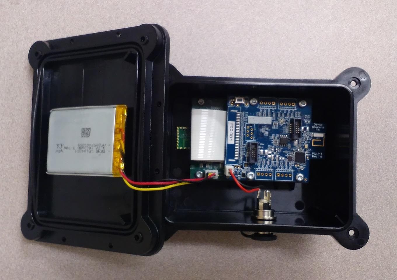
OXW-DS0039
Oct 05, 2015WIFI Gateway
Equipment Class
DTS - Digital Transmission System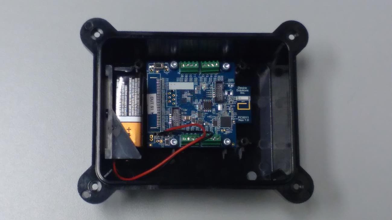
OXW-PA0022
Sep 30, 2015Sensor II Module
Equipment Class
DTS - Digital Transmission System
OXW-CA0007
Aug 09, 2015Electronic Cigarette Cartridge
Equipment Class
DXX - Part 15 Low Power Communication Device Transmitter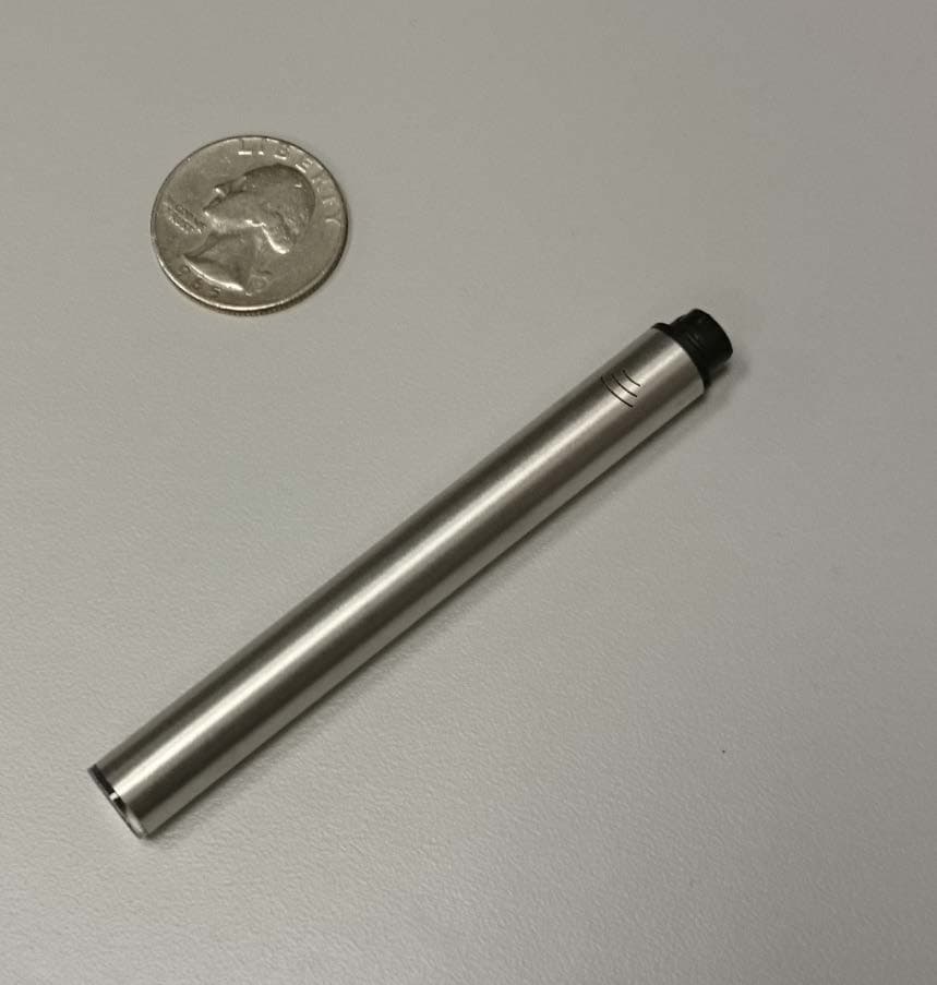
OXW-CA0006
Apr 27, 2015Electronic Cigarette
Equipment Class
DXX - Part 15 Low Power Communication Device Transmitter