OXW-PA0002Sensor Board Module
Device Solutions Inc.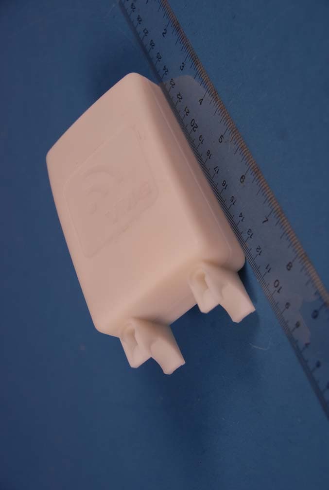
Click to zoom
Application Details
- Equipment Class
- DSS - Part 15 Spread Spectrum Transmitter
- Date of Grant
- Aug 22, 2012
- Application Purpose
- Original Equipment
- Date of Application
- Aug 22, 2012
- Equipment Note
- Sensor Board Module
- Frequency Range
- 904.80000000 - 924.80000000
- Company
- Device Solutions Inc.
- Country
- United States
Documents & Files
Document Text
Text extracted from the exhibit documents filed with the FCC. Open a document above to read the original.
Users Manual
Device Solutions Collector & Sensor Installation Instructions Revision History: PRELIMINARY FCC Caution: Changes or modifications not expressly approved by Device Solutions could void the user’s authority to operate this equipment. Note: This equipment has been tested and found to comply with the limits for a Class B digital device, pursuant to part 15 of the FCC Rules. These limits are designed to provide reasonable protection against harmful interference in a residential installation. This equipment generates, uses and can radiate radio frequency energy and, if not installed and used in accordance with the instructions, may cause harmful interference to radio communications. However, there is no guarantee that interference will not occur in a particular installation. If this equipment does cause harmful interference to radio or television reception, which can be determined by turning the equipment off and on, the user is encouraged to try to correct the interference by one or more of the following measures: Reorient or relocate the receiving antenna. Increase the separation between the equipment and receiver. Connect the equipment into an outlet on a circuit different from that to which the receiver is connected. Consult the dealer or an experienced radio/TV technician for help. Collector Installation 1. Provision the Collector in the server 2. Remove the four 3/8” #4 screws into the corners of the enclosure top that fasten it to the enclosure base. 3. Connect the battery 4. Reinstall the four 3/8” #4 screws into the corners of the enclosure top that fasten it to the enclosure base. 5. Attach the enclosure to a surface. The best RF performance is obtained by mounting the Collector to a vertical service. 6. Connect external power to the collector Sensor Installation 1. Remove the screws that hold the top of the Sensor's enclosure to the base 2. Verify the signal strength at the Sensor a. Open the Collector press the button to enter "install mode". b. Wait for the internal green LED to illuminate. c. Reboot the Sensor by removing and re‐installing the 9 volt battery d. Place the Sensor within 50 feet line of sight of the Collector e. Wait for the Sensor's internal LED to illuminate (up to 1 minute) f. The color of the LED indicates the following (red – poor signal quality, yellow – moderate signal quality, green good signal quality) g. Move the Collector and/or Sensor until the Sensor displays a good signal condition for at least 5 consecutive seconds h. Repeat c through g for each sensor i. Disable "install mode" for the Collector by pressing the button on the collector again (if this step is forgotten the collector will exit install mode in one hour) j. Turn off each Sensor by removing the 9 volt battery 3. Loosen the nut from the cable restraint shown above 4. Pass the transducer wires through the cable restraint 5. Tighten the cable restraint nut to the cable restraint 6. Attach the transducer wires to the terminal blocks. This connection depends on the type of transducer used. See the appendix for an example. 7. The total length of the transducer cable must be less than 10 feet 8. Install the 9 volt battery in the sensor 9. Re‐install the screws that hold the top of the enclosure to the base 10. Attach the enclosure to a surface. The best RF performance is obtained by mounting the Sensor vertically. Appendix: Ashcroft Pressure Transducer Installation Bare wire (shield drain wire) from the transducer is unused.
Attestation Statements
7/31/2012 Page 1(1) Device Solutions Inc Proprietary & Confidential http://www.device-solutions.com/ Phone/Fax: (919) 732-7872 Device Solutions Inc 1010 Copeland Oaks Drive Morrisville, NC 27560 July 10, 2012 Federal Communications Commission Authorization and Evaluation Division Equipment Authorization Branch 7435 Oakland Mills Road Columbia, MD 21046 To whom it may concern: We, the undersigned, hereby authorize PCTEST Engineering Laboratory Inc., to act on our behalf in all matters relating to applications for equipment authorization, including the signing of all documents relating to these matters. Any and all acts carried out by PCTEST Engineering Laboratory, Inc. on our behalf shall have the same effect as acts of our own. We also hereby certify that no party to this application is subject to a denial of benefits, including FCC benefits, pursuant to Section 5301 of the Anti-Drug Abuse Act of 1988, 21 U.S. C. 862. Sincerely, W. Christopher Lamb Chief Technology Officer Device Solutions Inc.
Attestation Statements
Applicant/Grantee Device Solutions Inc FCC ID: OXW-PA0002 Section 15.212 Modular Transmitters Request for Modular Approval Request for Limited Modular Approval Requirements EUT Conditions Comply (Y/N) Single Modular Approval Requirements 1 The radio elements of the modular transmitter must have their own shielding. The physical crystal and tuning capacitors may be located external to the shielded radio elements. Maximum output power is only 10dBm, with a duty cycle of much less than 10%. All layers ground filled and extensively stitched with vias. Most radio components are integrated into the primary IC. N 2 The modular transmitter must have buffered modulation/data inputs (if such inputs are provided) to ensure that the module will comply with Part 15 requirements under conditions of excessive data rates or over-modulation. The TX signal is directly synthesized by dedicated hardware from programmatically generated data. It should not be possible to over modulate or generate excessive data rates. Y 3 The modular transmitter must have its own power supply regulation. The supply into the radio IC is regulated and there are additional regulators internally. Y 4 The modular transmitter must comply with the antenna and transmission system requirements of Sections 15.203, 15.204(b) and 15.204(c). The antenna must either be permanently attached or employ a “unique” antenna coupler (at all connections between the module and the antenna, including the cable). The “professional installation” provision of Section 15.203 is not applicable to modules but can apply to limited modular approvals under paragraph (b) of this section. The antenna is permanently attached. Y 5 The modular transmitter must be tested in a stand-alone configuration, i.e., the module must not be inside another device during testing for compliance with Part 15 requirements. Unless the transmitter module will be battery powered, it must comply with the AC line conducted requirements found in Section 15.207. AC or DC power lines and data input/output lines connected to the module must not contain ferrites, unless they will be marketed with the module (see Section 15.27(a)). The length of these lines shall be the length typical of actual use or, if that length is unknown, at least 10 centimeters to insure that there is no coupling between the case of the module and supporting equipment. Any accessories, peripherals, or support equipment connected to the module during testing shall be unmodified and commercially available (see Section 15.31(i)). The unit was tested in stand-alone configuration. Y 6 The modular transmitter must be equipped with either a permanently affixed label or must be capable of electronically displaying its FCC identification number. (A) If using a permanently affixed label, the modular transmitter must be labeled with its own FCC identification number, and, if the FCC identification number is not visible when the module is installed inside another device, then the outside of the device into which the module is The PCB will be labeled with the FCC ID either in the silk screen or a sticker. Y installed must also display a label referring to the enclosed module. This exterior label can use wording such as the following: “Contains Transmitter Module FCC ID: XYZMODEL1” or “Contains FCC ID: XYZMODEL1.” Any similar wording that expresses the same meaning may be used. The Grantee may either provide such a label, an example of which must be included in the application for equipment authorization, or, must provide adequate instructions along with the module which explain this requirement. In the latter case, a copy of these instructions must be included in the application for equipment authorization. (B) If the modular transmitter uses an electronic display of the FCC identification number, the information must be readily accessible and visible on the modular transmitter or on the device in which it is installed. If the module is installed inside another device, then the outside of the device into which the module is installed must display a label referring to the enclosed module. This exterior label can use wording such as the following: “Contains FCC certified transmitter module(s).” Any similar wording that expresses the same meaning may be used. The user manual must include instructions on how to access the electronic display. A copy of these instructions must be included in the application for equipment authorization. 7 The modular transmitter must comply with any specific rules or operating requirements that ordinarily apply to a complete transmitter and the manufacturer must provide adequate instructions along with the module to explain any such requirements. A copy of these instructions must be included in the application for equipment authorization. These modules will only be integrated by the manufacturer into more complex products. Y 8 The modular transmitter must comply with any applicable RF exposure requirements in its final configuration. The module is integrated into products which are not used in proximity to humans. Any integrated devices will be reviewed for exposure limits Y A limited modular approval may be granted for single or split modular transmitters that do not comply with all of the above requirements, e.g., shielding, minimum signaling amplitude, buffered modulation/data inputs, or power supply regulation, if the manufacturer can demonstrate by alternative means in the application for equipment authorization that the modular transmitter meets all the applicable Part 15 requirements under the operating conditions in which the transmitter will be used. Limited modular approval also may be granted in those instances where compliance with RF exposure rules is demonstrated only for particular product configurations. The applicant for certification must state how control of the end product into which the module will be installed will be maintained such that full compliance of the end product is alw…
Text truncated - open the document above for the full version.
Cover Letter(s)
DeviceSolutionsInc 10lDCopelandOaksDrive Morrisville,NC 27560 July 30, 2012 FederalCommunicationsCommission Authorizationand EvaluationDivision EquipmentAuthorizationBranch 7435OaklandMillsRoad Columbia,MD 21046 RE:Requestof Confidentialityfor FCCID: OXW-PA0002 To WhomIt May Concern: Pursuantto Sections0.457and 0.459of the Commission'sRules(CFR47),and Section552 (b) (4) of the Freedomof InformationAct, DeviceSolutionsInc herebyrequestsconfidentialityand treatmentof certain informationaccompanyingthis application.The materialscontaintradesecretsand proprietary informationnot customarilyreleasedto the public.The publicdisclosureof thesemattersmightbe harmfulto the Applicantand provideunjustifiedbenefitsto its competitors. We are also herebyrequestShort-TermConfidentialityfor 180daysafterthe grantas outlinedin Public NoticeDA 04-1705.Thisprovisionwill giveDeviceSolutionsInc temporaryconfidentialityof commerciallysensitiveinformationpriorto productrelease. Tht d Pt d~ C fd t" I hibits r t d f IIe requese ermanenanernporarvon I en ra ex I I are IS e as 0 ows: PERMANENTANDSHORT-TERMCONFIDENTIALLIST Exhibit Description 1 BlockDiagram PERMANENT 2OperationalDescriptions 3 PartsListsand Tune-UpProcedure 4Schematics 5 ExternalPhotos SHORT-TERM 6 InternalPhotos CONFIDENTIAL 7Test-SetupPhotos 8 User'sManual The Applicantunderstandsthatpursuantto Rule0.457,disclosureof this applicationand all accompanyingdocumentations,whereapplicable,will not be madepublicbeforethe dateof the Grant for this application. Ge~e~l~J~ W. ChristopherLam'\ ChiefTechnologyOfficer DeviceSolutionsInc. 8/9/2012Page1(1) DeviceSolutionsInc Proprietary& Confidential http://www.device-solutions.com/ Phone/Fax:(919)732-7872
External Photos
DEVICE SOLUTIONS FCC ID: OXW-PA0002 Model: PA0002 External Photos EUT Type: Sensor Board Module Page 1 of 4 © 2012 PCTEST Engineering Laboratory Inc. EXTERNAL PHOTOGRAPHS DEVICE SOLUTIONS FCC ID: OXW-PA0002 Model: PA0002 External Photos EUT Type: Sensor Board Module Page 2 of 4 © 2012 PCTEST Engineering Laboratory Inc. DEVICE SOLUTIONS FCC ID: OXW-PA0002 Model: PA0002 External Photos EUT Type: Sensor Board Module Page 3 of 4 © 2012 PCTEST Engineering Laboratory Inc. DEVICE SOLUTIONS FCC ID: OXW-PA0002 Model: PA0002 External Photos EUT Type: Sensor Board Module Page 4 of 4 © 2012 PCTEST Engineering Laboratory Inc.
ID Label/Location Info
This device complies with Part 15 of the FCC Rules. Operation is subject to the following two conditions: (1) this device may not cause harmful interference, and (2) this device must accept any interference received, including interference that may cause undesired operation. Part no.: DS0001 Sensor Designed In USA by Device Solutions Inc Contains: FCC ID: OXW-PA0002 IC ID : 10572A-PA0002 VMG.us.com 6V 2A
Internal Photos
DEVICE SOLUTIONS FCC ID: OXW-PA0002 Model: PA0002 Internal Photos EUT Type: Sensor Board Module Page 1 of 2 © 2012 PCTEST Engineering Laboratory Inc. INTERNAL PHOTOGRAPHS DEVICE SOLUTIONS FCC ID: OXW-PA0002 Model: PA0002 Internal Photos EUT Type: Sensor Board Module Page 2 of 2 © 2012 PCTEST Engineering Laboratory Inc. FCC ID LABEL AND LOCATION
RF Exposure Info
Reviewed by: FCC ID: OXW-PA0002 MAXIMUM PERMISSIBLE EXPOSURE (MPE) DATA REPORT Quality Manager Test Report S/N: Test Dates: EUT Type: 0Y1207190978.OXW 07/27/2012 Sensor Board Module Page 1 of 7 © 2012 PCTEST Engineering Laboratory, Inc. REV 3.1MPE 02/09/09 Applicant Name: Date of Testing: Device Solutions Inc. 07/27/2012 3211 Moorefields Road Test Site/Location: Hillsborough, NC 27278 PCTEST Lab, Columbia, MD, USA USA Test Report Serial No.: 0Y1207190978.OXW FCC ID: OXW-PA0002 APPLICANT: Device Solutions Inc. EUT Type: Sensor Board Module FCC Rule Part(s): FCC Part 1 (§1.1310) and Part 2 (§2.1091) FCC Classification: FCC Part 15 Spread Spectrum Transceiver (DSS) Test Procedure: OET Bulletin 65 The device bearing the FCC Identifier specified above has been shown to comply with the applicable technical standards as indicated in the measurement report and has been tested in accordance with the measurement procedures specified in FCC OET Bulletin 65 (See Test Report). These measurements were performed with no deviation from the standards. Test results reported herein relate only to the item(s) tested. I authorize and attest to the accuracy of data. All measurements reported herein were performed by me or were made under my supervision and are correct to the best of my knowledge and belief. I assume full responsibility for the completeness of these measurements and vouch for the qualifications of all persons taking them. PCTEST certifies that no party to this application has been denied the FCC benefits pursuant to Section 5301 of the Anti-Drug Abuse Act of 1988, 21 U.S.C. 862. PCTEST ENGINEERING LABORATORY, INC. 6660-B Dobbin Road, Columbia, MD 21045 USA Tel. 410.290.6652 / Fax 410.290.6554 http://www.pctestlab.com RF EXPOSURE EVALUATION (MAXIMUM PERMISSIBLE EXPOSURE) Reviewed by: FCC ID: OXW-PA0002 MAXIMUM PERMISSIBLE EXPOSURE (MPE) DATA REPORT Quality Manager Test Report S/N: Test Dates: EUT Type: 0Y1207190978.OXW 07/27/2012 Sensor Board Module Page 2 of 7 © 2012 PCTEST Engineering Laboratory, Inc. REV 3.1MPE 02/09/09 TABLE OF CONTENTS 1.0 RF EXPOSURE EVALUATION – MAXIMUM PERMISSIBLE EXPOSURE (MPE) .........................3 1.1 INTRODUCTION ................................................................................................................................... 3 1.2 EUT DESCRIPTION .............................................................................................................................. 3 1.3 MPE REQUIREMENTS OVERVIEW..................................................................................................... 4 1.4 PROCEDURE........................................................................................................................................ 5 1.5 SUMMARY OF RESULTS ..................................................................................................................... 6 2.0 CONCLUSION..................................................................................................................................7 Reviewed by: FCC ID: OXW-PA0002 MAXIMUM PERMISSIBLE EXPOSURE (MPE) DATA REPORT Quality Manager Test Report S/N: Test Dates: EUT Type: 0Y1207190978.OXW 07/27/2012 Sensor Board Module Page 3 of 7 © 2012 PCTEST Engineering Laboratory, Inc. REV 3.1MPE 02/09/09 1.0 RF EXPOSURE EVALUATION – MAXIMUM PERMISSIBLE EXPOSURE (MPE) 1.1 Introduction This document is prepared on behalf of Device Solutions Inc. to show compliance with the RF Exposure requirements as required in §1.1310 of the FCC Rules and Regulations and RSS-102 of Industry Canada. The limit for Maximum Permissible Exposure (MPE), specified in FCC §1.1310, is listed in Table 1-1. According to FCC §1.1310 and RSS-102: the criteria listed in the following table shall be used to evaluate the environmental impact of human exposure to radio-frequency (RF) radiation as specified in §1.1307(b). Frequency Range (MHz) Electric Field Strength (V/m) Magnetic Field Strength (A/m) Power Density (mW/cm 2 ) Average Time (Minutes) (A) Limits For Occupational / Control Exposures (f = frequency) 30-300 61.4 0.163 1.0 6 300-1500 ... ... f/300 6 1500-100,000 ... ... 5.0 6 (B) Limits For General Population / Uncontrolled Exposure (f = frequency) 30-300 27.5 0.073 0.2 30 300-1500 ... ... f/1500 30 1500-100,000 ... ... 1.0 30 Table 1-1. Limits for Maximum Permissible Exposure (MPE) 1.2 EUT Description The Device Solutions Sensor Board Module FCC ID: OXW-PA0002 unit is a frequency hopping device that operates in the 900MHz ISM Band. Operation of this module is also possible while in close proximity to a FCC certified Telit Cellular/PCS band module (FCC ID: RI7DE910-DUAL). The device is set to transmit from the internal antenna of the Sensor Board Module and the RF exposure is evaluated. Since the Sensor Board Module is in close proximity to the Telit Cellular/PCS band module, co- location concerns are also addressed. EUT: Model: PA0002 Grantee: Device Solutions Inc. FCC ID: OXW-PA0002 Internal Antenna Gain: -1dBi Reviewed by: FCC ID: OXW-PA0002 MAXIMUM PERMISSIBLE EXPOSURE (MPE) DATA REPORT Quality Manager Test Report S/N: Test Dates: EUT Type: 0Y1207190978.OXW 07/27/2012 Sensor Board Module Page 4 of 7 © 2012 PCTEST Engineering Laboratory, Inc. REV 3.1MPE 02/09/09 1.3 MPE Requirements Overview Three different categories of transmitters are defined by the FCC in OET Bulletin 65. These categories are fixed installation, mobile, and portable and are defined as follows: o Fixed Installations: fixed location means that the device, including its antenna, is physically secured at a permanent location and is not able to be easily moved to another location. Additionally, distance to humans from the antenna is maintained to at least 2 meters. o Mobile Devices: a mobile device is defined as a transmitting device designed to be used in other than fixed locations and to be generally used in such a way that a separation distance of at least 20 centimeters is normally maintained between the transm…
Text truncated - open the document above for the full version.
Test Report
Reviewed by: FCC ID: OXW-PA0002 FCC Pt. 15.247 900MHz ISM BAND TEST REPORT (CERTIFICATION) Quality Manager Test Report S/N: Test Dates: EUT Type: 0Y1207190976.OXW 07/20 - 07/24/2012 Sensor Board Module Page 1 of 32 © 2012 PCTEST Engineering Laboratory, Inc. REV 2.3BTFI 05/16/12 Applicant Name: Date of Testing: Device Solutions Inc. 07/20 - 07/24/2012 3211 Moorefields Road Test Site/Location: Hillsborough, NC 27278 PCTEST Lab. Columbia, MD, USA USA Test Report Serial No.: 0Y1207190976.OXW FCC ID: OXW-PA0002 APPLICANT: Device Solutions Inc. Application Type: Certification Model(s): PA0002 EUT Type: Sensor Board Module Max. RF Output Power: 3.491 mW (5.43dBm) Conducted Frequency Range: 904.8 – 924.8MHz Type of Modulation: GFSK FCC Classification: FCC Part 15 Spread Spectrum Transmitter (DSS) FCC Rule Part(s): Part 15 Subpart C (15.247) IC Specification(s): RSS-210 Issue 8 Test Procedure(s): ANSI C63.4-2003/2009, ANSI C63.10-2009, DA 00-705 This equipment has been shown to be capable of compliance with the applicable technical standards as indicated in the measurement report and was tested in accordance with the measurement procedures specified in ANSI C63.4-2003/2009, ANSI C63.10-2009, and DA 00-705. Test results reported herein relate only to the item(s) tested. I attest to the accuracy of data. All measurements reported herein were performed by me or were made under my supervision and are correct to the best of my knowledge and belief. I assume full responsibility for the completeness of these measurements and vouch for the qualifications of all persons taking them. PCTEST certifies that no party to this application has been subject to a denial of Federal benefits that includes FCC benefits pursuant to Section 5301 of the Anti-Drug Abuse Act of 1988, 21 U.S.C. 862. PCTEST ENGINEERING LABORATORY, INC. 7185 Oakland Mills Road, Columbia, MD 21046 USA Tel. 410.290.6652 / Fax 410.290.6654 http://www.pctestlab.com MEASUREMENT REPORT FCC PART 15.247 / IC RSS-210 900MHz ISM Band Reviewed by: FCC ID: OXW-PA0002 FCC Pt. 15.247 900MHz ISM BAND TEST REPORT (CERTIFICATION) Quality Manager Test Report S/N: Test Dates: EUT Type: 0Y1207190976.OXW 07/20 - 07/24/2012 Sensor Board Module Page 2 of 32 © 2012 PCTEST Engineering Laboratory, Inc. REV 2.3BTFI 05/16/12 TABLE OF CONTENTS FCC PART 15.247 MEASUREMENT REPORT...................................................................................3 1.0 INTRODUCTION......................................................................................................................................4 1.1 SCOPE....................................................................................................................................................... 4 1.2 PCTEST TEST LOCATION........................................................................................................................ 4 2.0 PRODUCT INFORMATION .....................................................................................................................5 2.1 EQUIPMENT DESCRIPTION..................................................................................................................... 5 2.2 DEVICE CAPABILITIES ............................................................................................................................. 5 2.3 TEST CONFIGURATION ........................................................................................................................... 5 2.4 EMI SUPPRESSION DEVICE(S)/MODIFICATIONS.................................................................................. 5 2.5 LABELING REQUIREMENTS .................................................................................................................... 5 3.0 DESCRIPTION OF TEST ........................................................................................................................6 3.1 EVALUATION PROCEDURE..................................................................................................................... 6 3.2 AC LINE CONDUCTED EMISSIONS......................................................................................................... 6 3.3 RADIATED EMISSIONS ............................................................................................................................ 7 4.0 ANTENNA REQUIREMENTS ..................................................................................................................8 5.0 TEST EQUIPMENT CALIBRATION DATA..............................................................................................9 6.0 TEST RESULTS ....................................................................................................................................10 6.1 SUMMARY ............................................................................................................................................... 10 6.2 20DB BANDWIDTH MEASUREMENT .....................................................................................................11 6.3 OUTPUT POWER MEASUREMENT .......................................................................................................13 6.4 BAND EDGE COMPLIANCE.................................................................................................................... 14 6.5 CARRIER FREQUENCY SEPARATION.................................................................................................. 17 6.6 TIME OF OCCUPANCY ........................................................................................................................... 18 6.7 NUMBER OF HOPPING CHANNELS......................................................................................................21 6.8 CONDUCTED SPURIOUS EMISSIONS .................................................................................................. 22 6.9 RADIATED SPURIOUS EMISSION MEASUREMENTS.......................................................................... 26 6.10 …
Text truncated - open the document above for the full version.
Test Setup Photos
DEVICE SOLUTIONS FCC ID: OXW-PA0002 Model: PA0002 Test Set-Up Photos EUT Type: Sensor Board Module Page 1 of 3 © 2012 PCTEST Engineering Laboratory Inc. TEST SETUP PHOTOGRAPHS DEVICE SOLUTIONS FCC ID: OXW-PA0002 Model: PA0002 Test Set-Up Photos EUT Type: Sensor Board Module Page 2 of 3 © 2012 PCTEST Engineering Laboratory Inc. DEVICE SOLUTIONS FCC ID: OXW-PA0002 Model: PA0002 Test Set-Up Photos EUT Type: Sensor Board Module Page 3 of 3 © 2012 PCTEST Engineering Laboratory Inc.
Contact Information
Applicant
Chris Lamb(CTO)
Technical Contact
PCTEST Engineering Lab., Inc.Randy Ortanez
[email protected]410-290-6652
6660-B Dobbin Road · Columbia, Maryland · United States
Test Firm
PCTEST Engineering Laboratory, Inc.Randy Ortanez
Technical Specifications
| # | Rule Parts | Frequency Range | Power Output |
|---|---|---|---|
| 1 | 15C | 904.8 MHz - 924.8 MHz | 3.00 mW |
Other Applications from Device Solutions Inc.

OXW-AS0133
Jun 28, 2021Gateway
Equipment Class
DTS - Digital Transmission System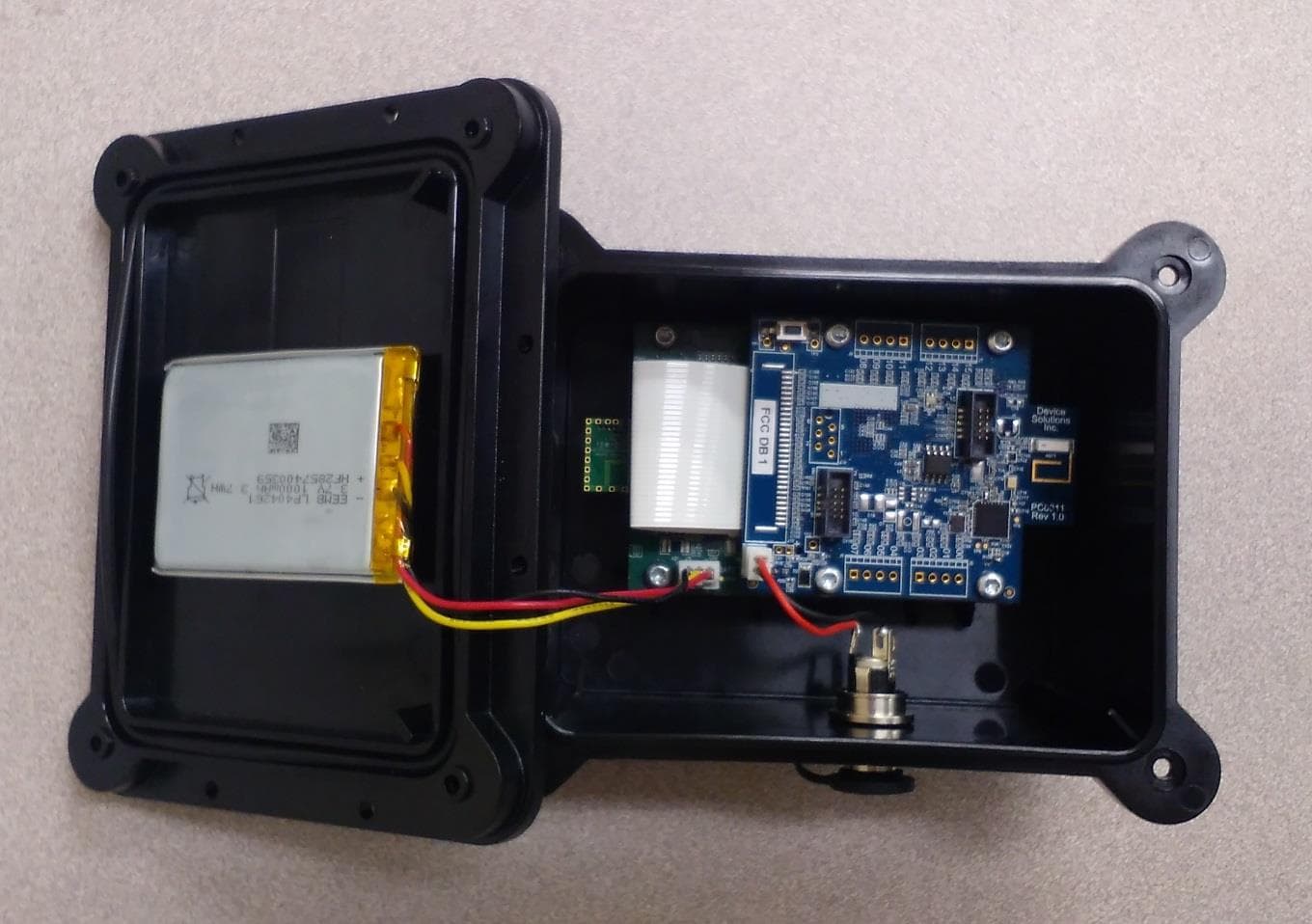
OXW-DS0039
Oct 05, 2015WIFI Gateway
Equipment Class
DTS - Digital Transmission System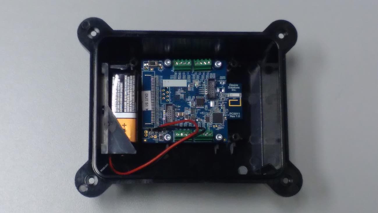
OXW-PA0022
Sep 30, 2015Sensor II Module
Equipment Class
DTS - Digital Transmission System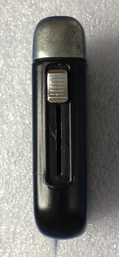
OXW-CA0007
Aug 09, 2015Electronic Cigarette Cartridge
Equipment Class
DXX - Part 15 Low Power Communication Device Transmitter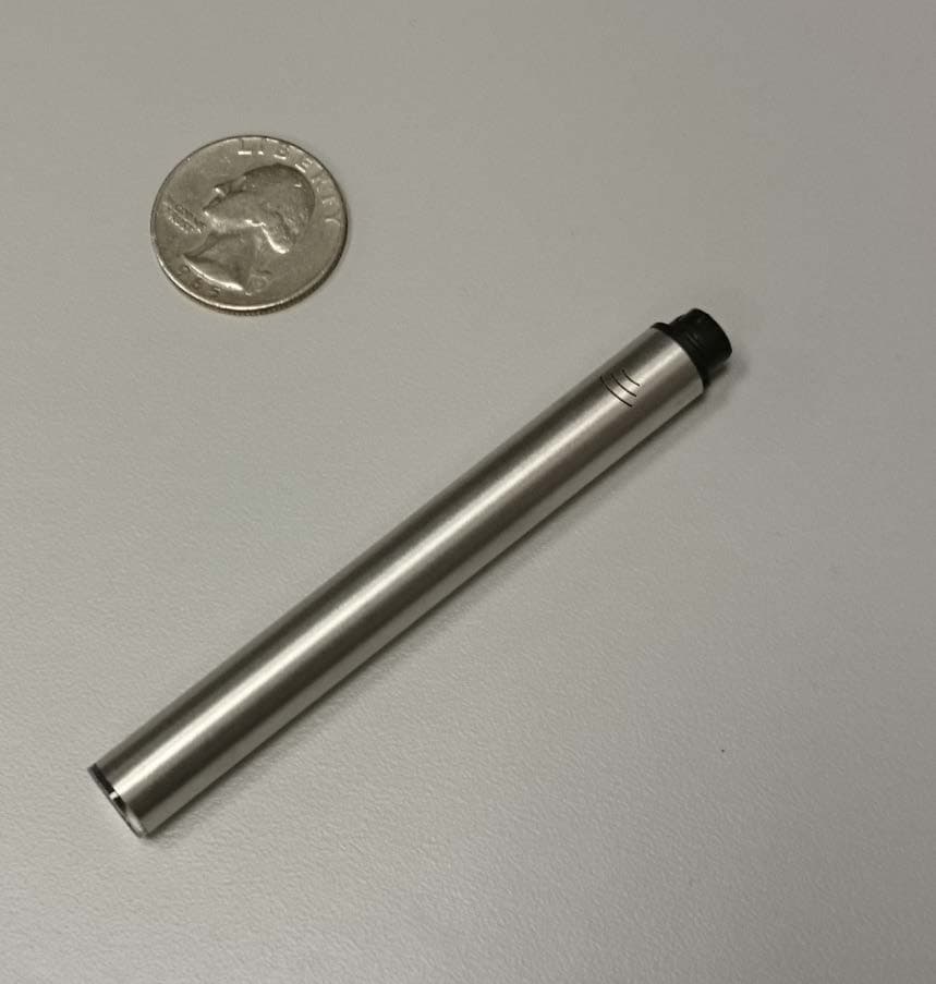
OXW-CA0006
Apr 27, 2015Electronic Cigarette
Equipment Class
DXX - Part 15 Low Power Communication Device Transmitter