OXZPV2000APreview Object Detection System
Preco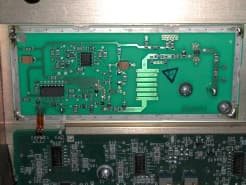
Click to zoom
Application Details
- Equipment Class
- DXX - Part 15 Low Power Communication Device Transmitter
- Date of Grant
- May 28, 2002
- Application Purpose
- Original Equipment
- Date of Application
- Oct 02, 2001
- Equipment Note
- Preview Object Detection System
- Frequency Range
- 5808.00000000 - 5808.00000000
- Company
- Preco
- Country
- United States
Documents & Files
Document Text
Text extracted from the exhibit documents filed with the FCC. Open a document above to read the original.
Users Manual
Preco Electronics, Inc. 415 N. Maple Grove, Boise, ID 83704 * (800) 453-1141 Copyright 2000Page 1 of 10 370-851-1B www.preco.com This member of the PreView family of object detect systems employ state of the art technology to provide vehicle operators and ground personnel with additional information to enhance productivity and safe operation of the vehicle. It is important that this document be read completely and understood thoroughly by all those involved in installation on and operation of vehicles equipped with this device. For Questions call 1-800-453-1141 betw een 7:00 AM and 5:00 PM Mountain Standard T ime Important Safety Notes • Read this document carefully. • Follow the installation instructions. • Install the vehicle and dash labels. • Remove the last two pages of this document and place in operator’s manual in vehicle for daily reference. • Train all Operators on the features and limitations of this product. Preco Electronics, Inc. 415 N. Maple Grove, Boise, ID 83704 * (800) 453-1141 Copyright 2000Page 2 of 10 370-851-1B www.preco.com PREVIEW PV2000 OBJECT DETECTION SYSTEM OPERATING INSTRUCTIONS, SPECIFICATIONS, AND INSTALLATION PROCEDURE Product Description The PreView Object Detection System is a system that detects both moving and stationary objects in a pre-defined area and reports the distance of the closest detected object via visual range indicators and an audible signal to a vehicle operator. The PreView system is designed as a back-up aid and is not to be the sole method for rear collision avoidance. The PreView Object Detection System does not comply with SAE J1741 AUG93 for Discriminating Alarm Systems for Construction and Agricultural Equipment. The PreView system is a solid-state, visual and audible warning device consisting of three major parts: an environmentally sealed 5.8GHz radar sensor unit located on the rear of the vehicle, the operator display unit mounted in the operator’s view in the cab of the vehicle, and the recommended external back-up warning alarm (not included). The operator display unit accepts data from the radar sensor and notifies the vehicle operator of a detected object with both a visual and an in-cab audible warning within 2/10ths of a second. The operator display provides a row of LEDs which are used to indicate the distance from the rear of a vehicle to a detected object. The number of LEDs lit depends on the distance to a detected object; i.e., the closer the unit is to an object the more LEDs will be lit. In addition to the LEDs, the buzzer output beep rate will also become faster as the distance to an object decreases. The operation of the system is dependent on the direction of movement of the vehicle. If the vehicle is in reverse and an object is detected both the operator display unit LEDs and buzzer will operate and the external backup alarm output will be enabled. If the vehicle is moving forward, only the operator display unit LEDs will be operating. The operator display provides a test switch, which allows an operator to test the PreView system without placing the vehicle in reverse gear. Once pressed, the operator has a 15 minute time period to exit the cab and walk behind the sensor unit to verify it is operating correctly by tracing the detection pattern at the rear of the vehicle. Correct operation is verified by a back-up alarm sounding (if attached) or by another person in the vehicle’s cab verifying the operation by viewing the display. The PreView system has a failure mode that is indicated by all LEDs flashing and the buzzer operating in the high frequency mode. DETECTION ZONES Approximate Detection Depth Feet Approximate Detection Depth Meters Number of Lights Illuminated In-Cab Operator Audible Alarm(s) Pulses/sec 24+8+11 21721 18631 15541 12452 9362 6272 3184 In addition to the operator display unit, a back-up alarm interface is also included in the radar sensor. If attached, the back-up alarm will only become active when an object is detected by the PreView system. We recommend the sound level of the external alarm be increased to a level appropriate for an urgent warning, which is typically 15 dB above the anticipated surrounding noise level of the vehicle in service, including the vehicle noise itself. Preco Electronics, Inc. 415 N. Maple Grove, Boise, ID 83704 * (800) 453-1141 Copyright 2000Page 3 of 10 370-851-1B NOTE: The back-up alarm and display audible indications will only become active if the vehicle is in reverse. The PreView system operator display unit will continue to indicate distance to detected objects on the display LEDs even while the vehicle is not in reverse. OPERATING MATRIX Machine ConditionOperator Yellow Warning Lights Operator Audible In- Cab Alarm External Back-Up Alarm Operator Green Status Light Engine OffOffOffOffOff Engine Running, IdleSensingOffOffOn Machine Forward GearSensingOffOffOn Machine ReverseIndicating distanceIndicating distanceEnabledOn Machine Reverse Object DetectedIndicating distanceIndicating distanceBeepingOn System Malfunction ForwardOff or On Max Rate Off or On Max RateXOff or Flashing System Malfunction ReverseOff or On Max Rate Off or On Max RateXOff or Flashing Depending on the malfunction, all the in-cab operator display unit LEDs will either be OFF or flashing at the maximum rate. If the LEDs are off or flashing the operator must operate the vehicle as if no object detection system were installed until the PreView system is returned to normal operation. Operational Theory The PreView system operates by transmitting a pulse of very low power electromagnetic energy. Any energy that strikes an object reflects a certain amount of this transmitted energy back to the PreView sensor. This returned energy is measured to determine an object’s distance from the radar sensor on the rear of the vehicle. The amount of energy that is returned is based on a few factors: Size- a larger object usually returns more energy than a small object. Distance - the farther away an obj…
Text truncated - open the document above for the full version.
Block Diagram
PV2000 Block Diagram Signal Generation 5Mhz PRF Transmitter Receiver Bandpass Filter Range Squared Amplifier Detector Micro Controller Communications I/F
Cover Letter(s)
1 of 1 May 10, 2001 Andy LeimerCC:David Chernomordik Federal Communications CommissionIntertek Testing Services 445 12 th Street, S.W.1365 Adams Court Washington, D.C. 20554Menlo Park, CA 94025 RE: FCC ID OXZPV2000A FCC Correspondence 22819 Dear Mr. Leimer: This letter is in response to your question about band-edge emission levels (reference your correspondence #22819). This device has been redesigned to emit a pulse with a main lobe bandwidth of less than 150 MHz. This allows the entire main lobe to be contained within the 5725 MHz – 5875 MHz Part 15.249 band. During manufacturing of this device, each unit will be tuned to center the main lobe between the band edges. Therefore any 15.249 band edge emissions at 5725 MHz and 5875 MHz may be deemed spurious per your statements made in Correspondence #22078: “The emissions outside the main lobe are considered to be spurious emissions ...” Referring to Plot #5 in the revised test report submitted April 30, 2002, it can clearly be seen that the main lobe is indeed less than 150 MHz. We actually designed for a bandwidth of 145 MHz (pulsewdith of 13.8 nanoseconds). In an ideal pulse, the null is extremely narrow; i.e., on the order of a few 10’s of KHz wide depending upon the pulse repetition frequency and pulsewidth used. During testing of the sample unit the markers were placed where the nulls were best estimated to be based upon the shape of the main lobe and the position of the 1 st sidelobes. This is why a value of 148 MHz was “measured” instead of the actual 145 MHz bandwidth designed for. During standard manufacturing of this product, the main lobe will be centered on each device. This is a typical center-frequency final tune-up done by a technician that is standard practice in the manufacturing of virtually all RF devices except for the simplest of circuits. Therefore all band edge emissions will be spurious only. Plot #6 clearly shows that the peak spur ious emission occurs at the upper band 1 st sidelobe. Plots # 7 & 8 make peak and average measurements respectively in accordance with your correspondence # 22078 mentioned above. Best Regards, Bria n Ba nd ha uer Senior RF Engineer Preco Electronics (208) 322-4212 [email protected] Preco Electronics, Inc. 415 N. Mapl e Grove Boise, ID 83709
ID Label/Location Info
%PDF-1.2 ı%âãÏÓı ı6 0 objı<<ı/Length 7 0 Rı/Filter /FlateDecode ı>>ıstreamı H‰”—Ù-4I•...-ø}h J¹g– ̆H<‚ ¼ D?ã>±fÆ©¾ h¤™¹ÕçË-ötåòúÏëO~ý•ÿõ ̄ןôâ þö—ןºò5Ëëî×Z ̄÷ù{^wyÕ•®<^÷}μõªs]¥Ù ̄ t «ì- Û5šcö‡¬©JýP ̄{¼ +WÛKòÿ‹Îö“ßì ÊÄS²òŸ ̄? g}¿Z‹‡×¿oe í“S½Šo¤ ø‰h'ÿ5ñ±ı³?ÂáõCö«•·Ö5ö‹èz~ÞÒ~ ́³(••zÎßFºÒzåYyQº@«ƒåy•þÏ¿UDw7Q/"ˆJE=¥«è7} ¤L”'Ÿ,Ó•èØï'e¢ZéõY3e7„LÓì[¿T••“Ð!G•É ̃ ́cšY ̄•v{dLCOJVaÑÐ3GÈ4ä0 5“•ýý„T4R¾j•‘n ̇ kn q•²k’C ̃dš<Ø”¬éC5•2Q)jÇûJrj¤\ ́®%••`c’ÚÔŠ·™52.Yü[¦Ð©z-`LÔØÏY³t/•\3%$– \ùý•LÓÕB¤Q«"ä¢zMþVÌ®H¹h°c²H튔‹– <ɪªˆˆ)ÈeØÒ«r•z ̃⊢ëJ"y?••51Ï’ÿ¼Ÿ”‹º~k¼ÃûI¹hèêÝ¢•)•i,¬a ‹Ô•ÉM†E"R.ªük] Ax»Îyª ̇ƒŒJŠÁ¡./4Ù_+¥»x3ƒTr`w²ÁNÐòögr2:K+)¼O½ù` \Ýœ•(÷²|ñ§v™³Fæ8ëÍ ßŠGa`\"áÔ(ô\•••Q`’¦»Ó ̃ä-&@Kæñ pAgA½§{ü!\1¥np>ÑU`9~ºš<ª»{¤ 1Ù2•¹î`‘:¶J,2EDPÑ—- Y]°ÒíÖc+ò»¶5 ̈:¾LÆ©m\Û•ÉJü7h* ̄Ý÷B ́BM= czp º+sTð- kÑTG...ëë5ön ̄Òs ̊?z;þ•C ́è'³Å! ô*yŠ¹Îù0 ¦ ̃}ÕóÊ... ̄ÆbÍX-|þ¡ ̄ ‡ÅÏn•ùð†¥ı«Ýþ¡ö_Œq^-ÎTH ̄g*”¥Omò•æ~GÙ ̧¶•*†‹Æ ̆»)ô¡ ́Ó óqêùÔ|,ó¼™B 7: ̄-– nwÌ ̃&š^¿ úxí•Eóã X ̄g2ê•»5tYyÜ:C•œ•è¶õ„õþð\HòXX‡L›ÚS³v ̆ ̊÷jw ̧¿ÄLzîe û~B ̧™-`O ́ +Éâ q³üE$ÕïWÙñ7Ç÷Ë|DvŒÐo£öÛð aôuÔ> ûE*Þš ́þ•ã • ́"šûrßz ̊iÐÓ>Ý‘×Aë×yf` ̄ãJýÓ² Æ• ¢íjP~\IÒÝ@Gz¬•›ì†Ú ¢ ̄\•Dü¼ 2sÿppûÐ~:·}È_ô_? {çòñCrÿ^ôQ&>ëñW¢ Ë}nÇE ̈ýV•ø•f\¥>Dpp£~{LØ.¾•>æ9 ̧^+öªÒI ́•B...¼¶ißéS S„NÓ;μñ ́Ë ́å hÑÅw• ̄ÊE =¬¥é-<PgH㕶ºå`:C•3% ñÈœ•-s÷¹ç³ıœ¶—3Þ < ̆•âÌfôæ•F–ºÛÞƒ ̧-² ́Â4öZi ̈ & ́:ó a"õhX9 ́ÞO ̊ŒZóôÆN Zi`9Ϭö©¹û ̄•!0jÍ;-# ̄6-Ù‹•0`Òšvú P ́hM;` ́‹Ö ́-•!0i¹‡— ?•À¬åÎîÒ@ e •2+H@ e ı-–þ ˆË•2’'šH eËØ ̃*P_—ÿ= ̃Á|ʆ^a<-% ̈•ÒQ3zG•âtÊf®q<EçÐQ³Rìú\• ̃O¹apƒE(Χ5ısD``<-© ̧Q ̃ ̃ ̃j¹—§;``F-4\•mÒCÁŒZÖîù Bk- ́ót¤`ˆ-s- • ̈oûμHù•u±ÑÝw •Ë¶•æ‡.©¶®æ (@Ç_¹ ̇•oD`r zıÝÈ[š`}7õE ̇Ö)L·³N¡ˆ”Ÿí£öoï'ôQƒ¡Þهߪùÿ$úº yøUÄ%÷Y§¿Ò|•ó/º‚•ÍW-Õ"rÓÉÏ»_©KoU&4ЖeÊNj‘ú¶ë‹•:w¿C ñÙŠ•x•ßH Û‘CðP™vSO-Ë>•#• •õ <xŒ•Œ¤•C© é•vpsþ£ Pc.á•vß ·–÷2§ðiæà î•D’êH!PÂ^¬YÕC• L•kY/ ̃ÐÉ£KÚ$k- â%N!¶Î-y•Ýˆ? 6•iy•ùª#Ô~‚4Ð5bƒ¡Wåh¿!ù 8=%1g«»ÃH26¶•sıõ`•¿eß >••íÍßÚ÷š ̧ø;@¡•©’Çc Zx ̆~ cû²„ËÙï ̇”‹$•p ̈l/ ”‹*•Ç"`™† U¾Ý~¤ ̊¹FÜ·Q¥×'ˆÆ5Uö/Ísm„\“„+Ão ̇ ¿ãMn¿• •kxWx ̊(ú÷ƒcó@å+Ç¢ Ç~ ̈±sW*ßö2ÀìÓŠÕÉ÷e™NQL G•ß©T... kμy Èé—å-¶;GÆO•SÀû ã,uyóøÅÉVÿv#dî³ØO-μŠŒkšø•m ̄Äq‰%&°\xˆãW •` ̃¢• ̃~£È•?gówo—•qÍä×懰 ́(B®¹å „»›GÈÍ e¬,É[S 0‡IÊz?¡Gæiî] Š- £íÌ•©‡ ̄÷ U"•B&("‚‘Wû •üYãðœ÷è1 ̆ •`èÂa-/ЋX ̈ •&¥â¥ı Ìnd£•s’0'Kʳ ̃Ù ̄8¹–Š"i'H ̃\ ¹—Œk¾• ¬çe•...`© ̈S•n’:– ¦•›Ÿ„êyø}iúI[Ñ9Ù¤cˆþÆ= ̄~{ŸUËÕ-û”ë!•“|,2š|ØΕÎ'Š%CÓ}. ÇÍ^ÊyN‡8þÀù“45ŠøÓ°,‚ ifb›r ̇ U `È5YÚ•}^$¶BòSò ••W ̈{¤fÁ ˆ‹$¥RøtÛ*B®••ïéÞ¢`¹F ó°V•„L ́Ä*- OUDÄ••ÇT-m«ƒ ̃‚•ªkéSc"â"©IœWμQFJE...Þ!kÎ0;`墮 ́=-N!å"qåÖ’Ùˆ)•e©H ʧú•R.âPmmXÆAÈ4...û- Ö–Ýı•—H‰lÝÇI`\#ífë•8È ̃†Ò•¿moV‹`r tþ &Û •μ¤Üòg ̄ÊEÒB4šCíö@™ ̈gqÐasˆB®‘wocX• ̇È4CMD±çš ̊™ˆ• =bºW#e¢¥•>9¼Æ•R&ºelhÓê#Bª©©È V¶Œ ̊ i²Þd•s5„\ ́8>W3•AÈ4Eo²< ́d•Jëü¶•aï'ä"m¦Ö ́ EÊDl%•- u6„LÓ¥‡kË›#•\£-Dz2‰Œi†tÅ ²»>#@¦™êì\ ́t/•LD£^Öoö @™è– ¼•D@¹HÎÇßt7•TÃéTo¢¥ ̃•“P6`§! æ>`L£••?šÚ•!•ÍK__Ý•!ÓPWÆ•º|, ́È4- ™©E`„+¦Ú°©ß ̈ ̄ iôhÚ\ˆ`’QÕÈ^••1ı ̆•GÊm© ̃•Ó¬* ́§Ù- ̊•ÜÜì7- o`¬IHênR°ß•À$9I Ñ–&êýw-Wt>}û ̃ ̃•š(nÁ‡·‹H ̧hŠKSfÔ4•”‰ª xœcu ̃È5Ú"vP ́rÍ-Ó[1 BÆ4-èÚÉR ̆@®éZð, ̈"ã•qS®fZ(`2M—‘‹GÅf EÈE2Yμlá„ iF’x¦d¤. kdj¢+Û½•qÍ-ßL• ̊•Ly* 3ú!\qK ̄RKowˆÄDK ̃,/_ ̇(•Mm«š_ (•éxA...Á¶ ̃Ê[â•IËB•!×p ·'•.蕈©Z~ „+Æ¥]©ý- ́—L60§D=I@ b5i‘“-••×,mÆ=-•9š±¤ao> ̊læHölð~ >z&™.æ•••úåÝÒû4Áå•æ– ¬©‡[èò• ̃Î0ñÑ0Gè4ºœ•xjû¶e.E*§ßÝç-È• ́"kS= Ö ̇Èûª).IgÕf ̊•o†šìOÞk•S„¼?©Z ́Í•Èx7P½°k= ̄È‹x‹Å• ̊ ̄ªM‹ß^å ^Äšä•? •^• ́Ìî; ́äå#Éîþ6ÈxfïÚ={` 'II ÛVÈxN•Òam£ ̃äY@ªÅq-„Üݳ {æ„Èœà›%8sd\Âåà¿Œ—Y’$) D ̄Ò'h –`âPyÿßA‹#ydUÛ|•%å `•’ËÃûóFðj ́;kûëfÜd@D-•ÅÔ×ØPŠx D{inC •É•÷[ºàZÓÀ¹÷±[‚ ıëD¼ ¡oºÎ•YrH ê ê3°&š•3u•-[•„ ̧B*·Îlæ7•ø ¶p;•|Á]š•J^£™e¼ªÇ 1Ð -ƒWwçÀ• ØËá¢LA¤íDÔ ̈¦â2d¬•t•R×ZIÙòÙñ„×Ç„+Šî£¢•I ̄ ̄º°(ŸD@óha)•.Š •U{ÚåöŒÁ•DV½KQ ̆!_ ̈hË ˆ×½#ô¾°’¡ı• œì¿•ú•ö ̃_T ñ• ôý•+EÞ-ˆ]7 ÕV=ç0••ùÔÞ#-C‚ +d+mg³ËıÃ- §Ö"ál ̈±·Ø¶® ̧]H ̄4Ë éQÎPx“ýZ×òÖŒ¡ÐÈN•î’ ¤œK †ôZ•’`BS¤ì6KJ‰À‡n=‰ ́oÍ yßC«{ÚwF^‡3ýª ̃ŠÓiƒv ©•‰iI;Ï••aì<3!QcÓÒñå ï„}Û ×†“Áû[r aSÄpâ¿`4ýw9v¾Ì•þévŸskˆ>)ËÊØR•ö hˆ ¿¤—¹¼s"(4ºDw’Ì@35g>•ŠC• –·êûN` ̄ë ̄YX_GÒC¡5_Œpó... ̄ˆkwYb g;™ HÏZJmwo—)ˆô}‹q÷Ó# "=Jñ6ËgÊ•DzNÒKØá•äš}·’ëv†ñ•Ì•4Cv»Ó³å ́f¶Š«Ù...À••AÐ,«&Ã·Ï ‹Ê4—Z (Sð¿SwÒ '% ̇Xà ̧ßX7S.º-¬Œê§Í•l²6ı}, •L¹H®I<oõ“d fÚ,-...éçM¹ ¾¬-í ̊²XbÊEåÞv•ï • ̃ò®;Ù‘aQ›•W450}uw Œ ̧ ̈km•kl¥ )ˆ¬ð.•}¦Ð ́,•M•|¢\4– ™~ô†L¡O Z'•“•ã•MZ!I„÷`û...•›×î+•h6¬-ZÓs<3•™[XÞ ̈2äš:m•·H?/È5íN7Á ̄:•ë@Î...&Ä•wÕ]•ÌB„kv Ðjûöx ̊••ý‘ÜÞ 8_/A.Ú_–-ekOƒ• kvç°ìıØó"È‹Î>0ÙêhX5Aè ́º-Ø ••)•μ¥Yà>õ‹(ôcf¡÷ÑØÞ ̃rÑ-¦v¢ÿ! ̄- ›:†îÅ?ôþïÝ ́Š ̈ ̄•V$ôPÜÖ›U¬ƒ•ˆ–-EA¢c*:Ãi Ö )ˆºÞN© •ZÕÈ?õr•w” 0G·•¬u¼e@á{†Ö¾Õá ˆ O£e-Ÿ %(•Ÿìv?;¿P‚B¤-ıº•¦ *j¼-t‡L...H¬×ãIƒ!hª\O{ÎÅf(4j×`’• Qï0NŸ7•Nê©/»μÞnË]Q¶[Ï×Dão'·•¡Ð¬Åv« ¹-μ•d ̧ ••m?“ãJP ̃.½H<z¦Âw½mW@a¼$Ý’ñúÁw-—í &l×x¹®õmºôÉdÓ5¾=—z¬åáÁ• ••‘ZÜr••¦«wr] Ó%O ̄ Û (\×z™®•ÂtI2%Óμ¾=—•Ù¾ào ̊ Ï% Îr4#0\·ú&{...IVËR¿ÅN’‡ÍR/T=pˆ ̊—5-•¹ "(\–9&Ë• •“eõ¾À±d(lÖЕk+f&Œ–¼• NÝ ̄e(|–ÖêÛ{E†¾|–%D¦¾|V«/Ÿu•âñLÇþ•õöYv ½ – #1_Vk±Ó:§( H Æ–¼ Ö™e—3ý8öNÌ—ÑrsC•;-» FÂi•|© §¥ç ̈ÎHX-¹AÍHŸ7•Vë2oo×NP8-õÇýÕçÍ„Ó’ð•×Ðá ́ •NK<ÈöL¾h‚ÂiI2ºáÒ™‚Ó²l½=“¥f¦à ́̆ôæ[c NË–°ÿe•‚àμ4yJŸè #Ca ̧$§'Õ¡ð\rp乂 Ï%!S è ̃ Ï¥)û†% ¢&WP ª• Ï%•0y® ̄...ç’Ø"Ï•Px®ö6]A...é’`ßiÌý$Qa ̈®þr]A...Hö»«‰ÏDT•ªR_®+ ̈•õÅ®+ — 3•Ç,%èåÌÂueè%Ê®+(ˆ-55k• §íZ•c‰Ï K£ ̧I_ª¢= Š³èqwQÔ •íþÇ-¦«Î”>Ç5„ØÉÞæÐN¥μ”!dšG¦é- ́c G¿ Ì' K·Q••-¦\ ́ë•h¦_Ùè]ò‘T¾þëš3ãš½Vy15ÍÑˈ9vÎ-ú8íÙ‡-[®f ¦G ̆ ́ñt, X c ̇éuh/)Ñé9 ̧hê|’‡ì †Zª ̊D!16Í•ëBò$ 9O[¥.• ̃åÅ !›ıYöIÂÄD ’$0 Â43 ̊@¹‘~7<@bpBúÐäˆ ]Ò‘qgx£È3„}© “Ãó ̄Å@¬h Õ?^ä>ñ»¦l×4e9– çia ̆ˆûÇ·š}ìÌsYIˆüKs ^Phl=gɱ>„²^^Û‰Ô¢] ýò·í? ̇zTí:Z i% ̊•k¹ÄåÛD ̄A¤e»•é‡ÈT<-•{|E ̄A3 d'm•$+> ̄A£åºíOø " ̊"mˆZ — ̃)<×g•<Ø•!Pä¬õ!$2O݉¦ L ̃Ó•4ÚmÔçöØ ̊•) õY~8„À¿èsê•LG•víWŠ jõs ù•ÌPh k2•fIÓR|-S!2 Wo‚B#ź•( •Õí•\ ̊ø¢%L ̇"à-쳇ò± e ̄$Mdn¦-o,efIˆ-uP?ˆòÀ ̄ï ?ÿ ̄`...v"ePå B+~`‹ ̇ifzÇ?•ã•¾òSyç óÓSóe••"OH'A ä•Wá'?ÞI,îÜ Z ̄þDÓ@ ̧Ѫ•WÆÜh••1¿tÈK ́A¡ñwð w1°ûë-z ̄ºy‚b&îõ®ê†Ú¹3 ̈?ˆúz‰Z þ³†î,êÃçý ¾nÿ]ıÆûî ×ÖÕK÷‰Ö uk{抃n÷e¢ÇÓ<S•5ˆ,»0 ̆ÑÐò=- ß•S•é ·ı1EF\±;7ÉIëòÀO ̊•j‘Ea÷ň‹f±îõúëš A£yt]^Oˆq‰x’š¼•1ÐLöc ¹èézƒI4¿ ™ ́#Í•i ́Ä”‹Šμ.ç• ̃‚蜬•I¢\TíÜN•0 ̆Ñ£&l‹LC kš-Ê•ÒÌ ̧ÄLT—ãÓ-• ̃Í£k” Ö4 ̄¹h{~ɃӾD ̊• •ëÙ</$ ̄^\ CŸÅû•F šRÖf1 •ÌËN ù' ̊ ̊ö ̄ñø¹‘•‚©VÚ•‚#÷ÿ)?$Å ›.yÇμåã C ½Z7n... ̊4•—îk4Ë A£ ̄ Š‰2 ̄Í£G<.ùóyC ².m×ú½|O ̄Ac ̄ÝËG&¢Ø•k7¼0 ̇ œoÏø¾’• ̊$Š‡ìag;••õU•×)- Aý’i¤•kìGD^ºÃ |'•i95À• 03 ̊lk+g÷ôÀ•bÊš ̧•+–Õ ̃Âui >]•CqÐz®8h‚~óp ̄...•”ÉÛ‚ “5·•;Ú®íЮÒãˆ| "#œŸ— iÌ•} ̄sÿøZ%oš~‡D ¿=èü~ÖÜÙZ•óμæzÖ•›ˆËPp íÑ@ˆô•o\ë/"Ó H‚ ÄıQGÒŠ ȱ{Lâó'Q$/±G{ ̈"•÷o…
Text truncated - open the document above for the full version.
Internal Photos
FCC ID: OXZPV2000A Photo of rear of PV2000 showing signal processing PCA (center) surrounded by shielded transmitter PCA (right side) and receiver PCA (left side). Photo of PV2000 receiver PCA mounted in antenna housing. Photo of PV2000 transmitter PCA mounted in antenna housing.
Internal Photos
Photo of rear of PV2000 showing signal processing PCA (center) surrounded by shielded transmitter PCA (right side) and receiver PCA (left side). Photo of PV2000 receiver PCA mounted in antenna housing. Photo of PV2000 transmitter PCA mounted in antenna housing.
Operational Description
For more information on PreView TM or any other Preco product, please contact your Preco representative, visit our website at www.preco.com or call Customer Service at (208) 323-1010 or (800) 453-1141. System Overview The PreView TM Object Detection System detects both stationary and moving objects out to a distance of 26 feet (8 meters) from the rear of a vehicle. It is a continuously sensing device that will immediately report to the vehicle operator when an object has been detected. The PreView TM system has many advantages over other object detection technologies such as ultrasonic and Doppler radar. One advantage the pulsed radar PreView TM system has over Doppler radar based object detection systems is the ability to detect objects without either the object or the vehicle moving. This feature is extremely helpful in allowing an operator to verify the area behind the vehicle is clear prior to engaging the reverse gear. Operation The PreView TM radar sensor operates by looking for an echo of a regularly transmitted, small, energy pulse. At microwave frequencies, almost everything in nature reflects a significant portion of the electromagnetic energy striking it. Metal is the best reflector, but wood, foliage, rubber, and even rain will reflect some of the energy. Only when enough energy is reflected back to the sensor will the PreView TM be able to detect an object. The obvious consequence of this is that larger metallic objects reflect more energy than smaller porous objects and flat, perpendicular objects reflect more energy than rounded objects. Basically, the PreView TM system will detect vehicles, people, and walls, but it may not detect small posts and bushes due to the shape of these objects. The PreView TM sensor detection zone is primarily triangular shaped, fanning outward from the sensor. The edges of this detection zone will not seem to be tightly controlled since as stated above, detection is largely based on the object’s shape and density. So the zone will be slightly wider when a vehicle is the object and slightly narrower with a small object. For more information on PreView TM or any other Preco product, please contact your Preco representative, visit our website at www.preco.com or call Customer Service at (208) 323-1010 or (800) 453-1141. Operator Display The PreView TM display provides two methods for operator notification, a group of lights as well as an audible alert. A single green light is used to indicate the system has power applied and is operational. During initial powering, the display will run a self-test routine and will briefly sound the alert and flash all the lights to let the operator know that the unit is working correctly. The PreView TM Object Detection System is designed to operate both when the vehicle is in reverse as well as when it is not in reverse. When the vehicle is not in reverse, the system will detect objects but only report them with the lights. When the operator places the vehicle in reverse, both the lights and the audible alert will provide operator notification. The display lights and audible alert provide the operator with an idea for an object’s relative distance. As the vehicle gets closer to an object the more lights will activate and the audible alert will go from slow to fast beeping. Some detection systems’ displays will not automatically clear when an object has left the detection zone. The PreView TM system, which is continuously sensing, will indicate to the operator that the detection zone has been cleared by the absence of display lights. If an auxiliary back up alarm is used with the PreView TM system, it will only sound when the vehicle is in reverse and an object has been detected. This provides a warning to any person(s) who may be behind the vehicle when it is required, i.e., when they are directly behind the vehicle. This unique feature also minimizes the annoyance of a continuously sounding back up alarm. During the initial placing of the vehicle in reverse, the back up alarm will provide a three-beep warning and then remain silent until an object has been detected. Fail Safe The PreView TM object detection system is designed for years of trouble-free use. But in the event of a failure, the system will provide notification to the vehicle operator. In techno-speak, this is know n as a “fail-safe” system. Meaning, other than a failure due to a loss of power, the display will alert the operator to a system failure by continuously flashing the display lights and sounding the audible alert. Environmental Considerations The PreView TM sensor is designed to operate in extreme environmental conditions. Heat, cold, rain, snow, high winds, and fog do not effect the operation of the unit. In fact, the PreView TM Object Detection System is designed to operate in temperatures from 185 ° F (+85 ° C) to –40 ° F (-40 ° C). But like in most cases, care must be taken w hen mounting the PreView TM sensor close to vehicle exhaust systems and radiators. The temperature in close proximity to these areas may exceed the maximum operating temperature. In addition to temperature extremes, the PreView TM sensor has been designed to survive in both on and off road operating conditions. This means that the PreView TM sensor, which is filled with a urethane material, can survive high vibrations without losing pieces or falling apart. The PreView TM sensor does not require cleaning but it can be washed, even with a high-pressure fire hose, without damage since the unit is completely sealed. Installation Installation of the PreView TM Object Detection System is straightforward. There is an interconnect cable between the sensor and display which must be routed from the rear of the vehicle to the vehicle’s cab. Power should be connected to the sensor from a key switched power source so that the system will not continue to operate when the vehicle is not running. The reverse light wire should be spliced to provide a reverse signal to the sensor a…
Text truncated - open the document above for the full version.
Operational Description
MODELING OF A REALISTIC PULSE DESENSITIZATION FACTOR CORRECTION FOR CALCULATING PEAK POWER INTERFERENCE POTENTIAL B.D.B 01/04/02 This document Models an ideal pulsed RF carrier waveform in the time domain and in the frequency domain. The model is then used to depict the effects of using a wide bandwidth receiver to view the actual line spectrum. FCC rules indicate that the full pulse desensitization factor (PDF) needs to be applied even at the band edges of line spectrum measurements to account for what a worst-case wideband receiver might see as effective measured (interfering) peak power levels due to receiving multiple spectral lines. HP Application Note 150-2 indicates that a resolution bandwidth of about 1/2 of the main lobe (1/pulsewidth) would be required to effectively measure the peak pulse power as predicted by adding the PDF to the power measured in line spectrum mode (actual CW component amplitudes). This is confirmed in the modeling below. In the case of the Preview Radar, this would require a receiver bandwidth of about 125 MHz. But according to the FCC's proposed rulemaking for ultra-wideband devices (FCC 00-163, page 20), the "widest victim receiver bandwidth likely to be encountered" is only 50 MHz. Therefore, it is unfair to require application of the full PDF for our product. The modeling below graphically demonstrates that for the Preview product the PDF correction should be reduced by about 7dB for a more realistic calculation of the threat peak power. Therefore a 21 dB PDF should more realistically be applied instead of the full theoretical 28 dB @ 5MHz PRF. MATHEMATICAL EXPRESSION OF PULSED RF CARRIER - TIME DOMAIN A1Amplitude Factor (Peak Unmodulated Carrier Amplitude) τ . 810 9 Pulsewidth Ψ . 20010 9 Pulse Repetition Periodπ3.14159 Fp 1 Ψ Pulse Repetition Frequency (Hertz) Frf . 5.810 9 RF Carrier Frequency (Hertz) t..,0 . 0.110 10 . 2010 9 Time span for graphical evaluation Number of frequency summation terms is limited for practical calculation f()t =100 100 n .. . Aτ Ψ sin .. nπτ Ψ .. nπτ Ψ cos() ... 2π()Frf . nFpt TIME-DOMAIN PULSE WAVEFORM An 8 nanosecond pulse centered at time=0 and repeating every 200 nanoseconds 2 1 0 1 2 0410 9 810 9 1.210 8 1.610 8 210 8 f()t t PULSED RF CARRIER IN THE FREQUENCY DOMAIN rng100+/- Integer Number range of Frequency Components used in calculation above i..0() . 2rng2 * range to allow storage of all values in MCAD array The Amplitudes of all of the Frequency Components above. (Slightly off-center sinc-function) (value needed to avoid a MCAD) (induced singularity at n = 0 term) FA i = . 1rng rng n .. . Aτ Ψ sin .. nπτ Ψ .000000001 .. nπτ Ψ .000000001 δ(),nirng F i Frf . ()irngFpThe Frequency Components (Hertz) FAdB i . 20logFA i Frequency Component Amplitudes in decibels APPROX. IDEAL TRANSMIT OUTPUT POWER LINE SPECTRUM An 8 nanosecond pulse centered at time=0 and repeating every 200 nanoseconds 70 65 60 55 50 45 40 35 30 25 20 5.310 9 5.410 9 5.510 9 5.610 9 5.710 9 5.810 9 5.910 9 610 9 6.110 9 6.210 9 6.310 9 FAdB i F i RELATIONSHIP OF POWER SPECTRUM TO PULSE DESENSITIZATION FACTOR PDFdB . 20log() . τFpDefinition of PDF in decibels Since peak amplitude = 1 (0 dB), the center frequency term above has theoretical amplitude equal to (0 - PDF) dB. This is confirmed above. =PDFdB27.959 EFFECT OF WIDE-BAND MEASUREMENT EQUIPMENT & RECEIVERS From HP Application Note 150-2, the resolution bandwidth of a spectrum analyzer (or receiver bandwidth) must be less than 0.3 * PRF to accurately resolve the amplitudes of the line spectral components shown above. For RBW > PRF, the receiver "sees" multiple spectral components which results in a higher perceived power. HP Application Note 150-2 suggests that a RBW equal to about 1/2 of the main lobe will effectively result in measuring the peak amplituded of the unmodulated RF carrier (0 dB in this case). The equations below effectively sweep a wideband receiver across the actual line spectrum obtained above and adds multiple spectral lines together to obtain a perceived power just as an actual spectrum analyzer would do. The validity of the equations below may be checked by using a resolution bandwidth right at the edge of still being valid for obtaining a line spectrum (compare to above plot) and by using a resolution bandwidth equal to 1/pulsewidth. For the later case, a peak amplitude very near 0 dB should be observed. Measurement Resolution Bandwidth (Hertz) - This value is at the edge of being valid for line spectrum mode. (Must be an even number for MCAD to avoid integer errors below.) rbw . 210 6 numFfloor rbw Fp Integer Number of Spectral Components Encompassed by Resolution Bandwidth (Hertz) j.. numF 2 . 2rng numF 2 New array size of Wideband Measured Spectral Components PA j =j numF 2 j numF 2 n FA n New Wideband Measured Spectral Components PAdB j . 20logPA j Frequency Component Amplitudes in decibels APPROX. MEASURED OUTPUT POWER SPECTRUM Resolution Bandwidth = 2MHz -> Confirmed Still Essentially Line Spectrum) 70 65 60 55 50 45 40 35 30 25 20 5.310 9 5.410 9 5.510 9 5.610 9 5.710 9 5.810 9 5.910 9 610 9 6.110 9 6.210 9 6.310 9 PAdB j F j Resolution Bandwidth configured for Full Pulse Spectrum in Accordance with App-Note 150-2 (Note: Must repeat entire equation set for MCAD to recalculate) rbw . 13010 6 Measurement Resolution Bandwidth (Hertz) numFfloor rbw Fp j.. numF 2 . 2rng numF 2 PA j =j numF 2 j numF 2 n FA n PAdB j . 20logPA j APPROX. MEASURED OUTPUT POWER SPECTRUM Resolution Bandwidth = 130MHz (Full Pulse Spectrum) -> Confirms App-Note 150-2 50 45 40 35 30 25 20 15 10 5 0 5.310 9 5.410 9 5.510 9 5.610 9 5.710 9 5.810 9 5.910 9 610 9 6.110 9 6.210 9 6.310 9 PAdB j F j j Resolution Bandwidth configured for Worst-Case Victim Receiver Bandwidth = 50 MHz (Note: Must repeat entire equation set for MCAD to recalculate) rbw . 5010 6 Measurement Resolution Bandwidth (Hertz) numFfloor rbw Fp j.. numF 2 . 2rng numF 2 PA j =j numF 2 j numF 2 n FA n PAdB j . 20logPA j APPROX. MEASURED …
Text truncated - open the document above for the full version.
Test Report
1365 Adams Court, Menlo Park, CA 94025 Preco, Inc., Model No: PV2000Date of Test: August 27 to September 13, 2001 File: 30059451Version 1.0Page 1 of 20 FCC 15.249 TABLE OF CONTENTS 1.0Summary of Test Results............................................................................................................2 2.0General Description....................................................................................................................3 2.1Product Description.........................................................................................................3 2.2Related Submittal(s) Grants..............................................................................................3 2.3Test Methodology............................................................................................................3 2.4Test Facility....................................................................................................................3 3.0System Test Configuration..........................................................................................................4 3.1Justification.....................................................................................................................4 3.2EUT Exercising Software..................................................................................................4 3.3System Test Configuration................................................................................................5 3.3.1Support Equipment..............................................................................................5 3.3.2Block Diagram of Test Setup...............................................................................5 3.4Equipment Modification...................................................................................................6 3.5Additions, deviations and exclusions from standards..........................................................6 4.0Emission Results.........................................................................................................................7 4.1Test Procedure................................................................................................................7 4.2Field Strength Calculation.................................................................................................8 4.3Radiated Emission Data...................................................................................................9 4.3AC Line Conducted Emission Data.................................................................................12 4.4Emission Plot.................................................................................................................13 6.0List of test equipment...............................................................................................................22 7.0Antenna Requirement...............................................................................................................23…
Text truncated - open the document above for the full version.
Contact Information
Applicant
Dale Hessing(Chief Technical Officer)
Technical Contact
Intertek Testing ServicesDavid Chernomordik
[email protected]650.463.2900
1365 Adams Ct. · Menlo Park, California · United States
Non-Technical Contact
PrecoJohn Fadgen
[email protected]208.323.1000
Test Firm
Intertek Testing Services NA Inc.John Quigley
Technical Specifications
| # | Rule Parts | Frequency Range | Power Output |
|---|---|---|---|
| 1 | 15C | 5.81 GHz - 5.81 GHz | - |
Other Applications from Preco
OXZSTAL79
Feb 19, 2026Vehicular Radar
Equipment Class
VRD - Part 95 Vehicular Radar Systems
OXZSENTRY79
May 11, 2023Field Disturbance Sensor
Equipment Class
VRD - Part 95 Vehicular Radar Systems
OXZPCLK2020
Jul 01, 2021PRECOlink
Equipment Class
DTS - Digital Transmission System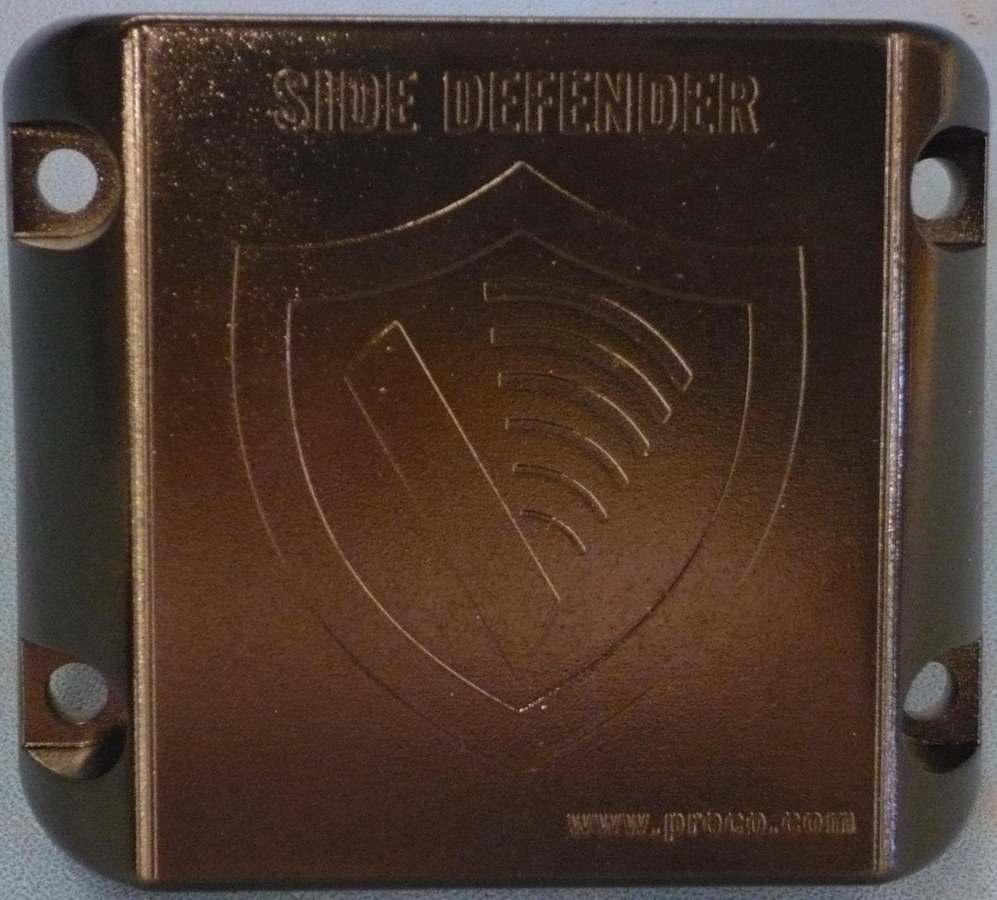
OXZSTNB2019
Apr 01, 2020PreView Sentry SX97
Equipment Class
DXX - Part 15 Low Power Communication Device Transmitter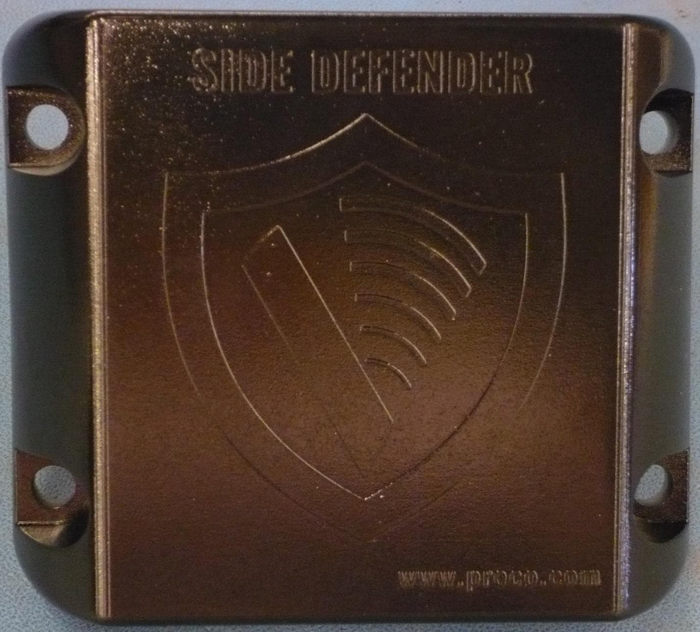
OXZTHUN2019
Apr 01, 2020PreView Sentry ST97 and Side Defender II SDII97
Equipment Class
DXX - Part 15 Low Power Communication Device Transmitter