OYT-3201220RF Motor Control System
AM Equipment
Click to zoom
Application Details
- Equipment Class
- DSC - Part 15 Security/Remote Control Transmitter
- Date of Grant
- Jun 19, 2000
- Application Purpose
- Original Equipment
- Date of Application
- Apr 17, 2000
- Equipment Note
- RF Motor Control System
- Frequency Range
- 315.00000000 - 315.00000000
- Company
- AM Equipment
- Country
- United States
Documents & Files
Document Text
Text extracted from the exhibit documents filed with the FCC. Open a document above to read the original.
Users Manual
The Manual of RF Motor Control System Caution : Any changes or modifications in construction of this device which are not expressly approved by the party responsible for compliance could void the user’s authority to operate the equipment. This device complies with part 15 of the FCC Rules. Operation is subject to the following two conditions: (1) This device may not cause harmful interference , and (2) this device must accept any interference received, including interference that may cause undesired operation. II III Fig 2 . RF Remote Controller LED I II III No Action UP DOWN SETTING and TEST RF Transmit Antenna RF Motor Control System (+12V) (SW_UP) (MOTOR UP) (GND) (SW_DOWN) (MOTOR_DOWN) SETTING SW Controller LED 6P Connector DC Jack Fig 1 . Main Controller I Operating manual 1. Wiring 1-1 Wires as Fig 3. 1-1-1 The LED in main controller is lighted for 3 seconds and comes on and off with the interval 1 se conds afte r the powe r is s upplie d. 2. Setting for RF remote controller with main controller (see Fig 1, Fig 2) 2-1. Pus h t he SETTING switch. The controller LED is lighted for 6 seconds 2-2. Push the no. 3(III) switch in RF remote controller (Do not push the other switches). 2-3. The LED comes on and off rapidly after the completed setting when push the no.3 switch Caution : If the LED does not come on and off rapidly in spite of pushing No. 3 switch, go to 2 3. Working If you want to upward, push No.1 switch. Then, push No.2 switch for downward with the completed set RF remote controller. + - 12V Battery motor UP Motor SW UP SW DOWN Fig 3 . Wiring GND (-) connect motor DOWN 4. How to use the remote controller 4-1. No.1 switch in the RF re mote controller If you want to move the motor to upward direction, push No.1 switch until where you want. The LED comes on and off rapidly, the motor works upward during the switch No.1 is pushed. (When the up signal is detected, the motor is worked automatically) 4-2. No.2 switch in the RF re mote controller If you want to move the motor to downward direction, push No.2 switch until where you want. The LED comes on and off rapidly, the motor works upward during the switch No.1 is pushed. (When the down signal is detected, the motor is worked automatically) 4-3. No.2 switch in the RF re mote controller Use the No.3 switch for the test and setting. LED comes on and off rapidly.
Block Diagram
Power Supply BAT, SW1,SW2, SW3 Oscillator RO1 Amplification & ModulationQ1, R6 CODE GENERATOR FP527, R5 DIAGRAM OF RF REMOTE CONTROLLER POWER FLOWSIGNAL FLOWMODULATION Description of RF Remote Controller Circuit Power is supplied with pushed one among the SW1, SW2, or SW3, then oscillates in Resonators.At the same time, the oscillated frequency is amplified and modulates the code from FP527 in R6, and Q1.The code of FP527 has identical code as the followings. Output Format : Preamble C0 ~ C19 (1 Million Codes) D0 D1 D2 D3 Preamble : Output Data Frame : 4 Ick 12 Ick Data (H) : 4 Ick 12 Ick 12 Ick 4 Ick Data (L) : Define : 1 Ick = 8 OSC clock
External Photos
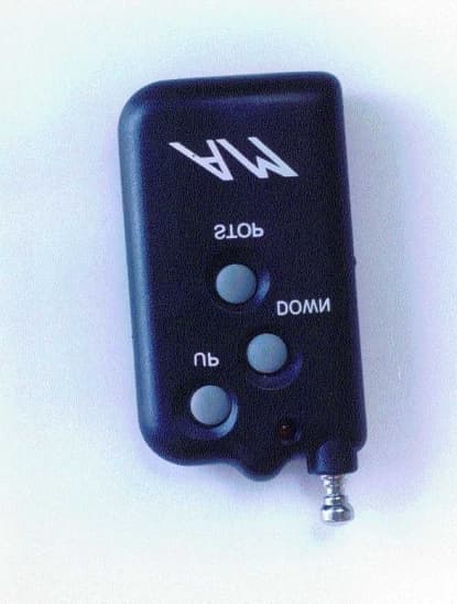
External Photos < Front Side > <Re ar Side >
ID Label/Location Info
ID LABLE
Internal Photos
Internal Photos <Front Side of PCB> <Rear Side of PCB>
Schematics
CIRCUIT
Test Report
KTL Korea Testing Laboratory Page 1 of 15 TEST REPORT This test report only responds to the tested sample and shall not be reproduced except in full without written approval of the Korea Testing Laboratory. Tested and reported by Reviewed by Jeong-Min Kim , Senior Engineer Seok-Jin Kim , EMC Team Leader KOREA TESTING LABORATORY FG101-01-02-00 222-13, Guro-Dong Guro-Gu Seoul Korea 152-053 http://www.ktl.re.kr Ref. Report No. 00-341-003-02 Name and address of the applicant AM Equipme nt P.O. BOX 790 402 E. HAZEL JEFFERSON, OR 97352 U.S.A. Standard / Test regulation FCC Part 15, Subpart C Test result Pass Incoming date : January 21, 2000 Test item( s) ; Security/Re mote Control Transmitter (RF Moto r Co nt rol Syste m) Model/type ref. ; MIDAS2 Manufacturer ; SAM- M ELECTRON Additional information ; -Re quire d Aut ho riz atio n : Ce rtificatio n -FCC ID. : OYT-3201220 Test date : March 28, 2000Issue date : April 14, 2000 Ref. Report No. 00-341-003-02 2 Page of 15 TABLE O F CONTENTS I. GENERAL INFORMATION ............................................................................................................ 3 1. Grantee Name and Mailing Address 2. Manufacturer's Name and Mailing Address 3. Equipment Descriptions 4. Rules and Regulations 5. Measuring Procedure 6. Date of Measurement α. GENERAL REQUIREMENTS OF THE EUT .................................................................4 1. Labelling Requirement (Section 15.19) 2. Information to User (Sections 15.21) 3. Special Accessories (Section 15.27) 4. Compliant Conditions (Section 15.231) β. INPUT POWER MEASUREMENT (Section 15.31) ......................................................................6 χ. RADIATED EMISSION MEASUREMENT (Section 15.231) .......................................................7-13 1. Test Procedure 2. Photograph for the worst case configuration 3. Sample Calculation 4. Measurement Data 5. Reference Data δ. OCCUPIED BANDWIDTH MEASUREMENT (Section 15.231).................................................14 ε. TEST EQUIPMENTS USED FOR MEASUREMENT..................................................................15 Ref. Report No. 00-341-003-02 3 Page of 15 . GENERAL INFORMATION 1. Grantee Name and : AM Equipment Mailing Address P. O. Box 790, 402 E. HAZEL JEFFERSON, OR 97352 U.S.A. 2. Manufacturer's Name and: SAM-M ELECTRON Mailing Address239-12 Gasan-Dong, Kumchon-Gu, Seoul, Korea 152-023 3. Equipment Descriptions 3.1 Operating Frequency : 314.95 MHz 3.2 Detect Method : Pulse Code Signal 3.3 Used Oscillator: 314.95 MHz (Resonator) 3.4 Power Suppy: DC 6V (Battery) 4. Rules and Regulations: FCC Part 15, Subpart C 5. Measuring Procedure: ANSI C63.4-1992 6. Date of Measurement 6.1 Line Conducted: Not Applicable 6.2 Radiated Emission : March 28, 2000 Ref. Report No. 00-341-003-02 4 Page of 15 . GENERAL REQUIREMENTS O F THE EUT 1. Labelling Requirement (Section 15.19) This device complies with Part 15 of the FCC Rules. Operation is subject to the following two conditions: (1) this device may not cause harmful interface, and (2) this device must accept any interference received, including interference that may cause undesired operation. 1.1 Location of Label : Manual for Installation and Operating Instruction 1.2 How Applied : Printing 2. Information to User (Section 15.21) The following or similar statements were provided in the manual for user instruction. Please refer page 1 of the attached manual for details. CA UT ION : A ny c ha nges or modifications i n cons truc tion o f this device w hich are not e xpressly approved by the party responsible for compliance could void the user's authority to operate the equipment. 3. Special Accessories (Section 15.27) 3.1 Were the special Accessories provided? [ ] yes, [ x ] no 3.2 If yes, details for the special accessories are as follows : 3.3 If yes, were the appropriate instructions provided on the first page of the text concerned with the device? [ ] yes, [ ] no 3.4 Are these accessories provided of the type which can be readily obtained from multiple retail outlets ? [ ] yes, [ ] no And therefore does the manual specify what additional components or accessories are required to used in order to comply with the Rules? [ ] yes, [ ] no Ref. Report No. 00-341-003-02 5 Page of 15 4. Compliant Conditions (Section 15.231) 4.1 Was the EUT used for continuous transmissions, such as voice or video, and data transmission ? [ ] yes, [ x ] no 4.2 Was the EUT manually operated ? [ x ] yes, [ ] no If yes, did the EUT employ a switch that would automatically deactivate the transmitter within not more than 5 seconds of being released ? [ x ] yes, [ ] no 4.3 Was the EUT automatically activated ? [ ] yes, [ x ] no If yes, did the EUT cease transmission within 5 seconds after deactivation ? [ ] yes, [ ] no 4.4 Was the EUT used for periodic transmissions at regular predetermined intervals ? [ ] yes, [ x ] no Ref. Report No. 00-341-003-02 6 Page of 15 . INPUT POWER MEASUREMENT (Section 15.31) INP UT POWER 89.4 mW Note : 1. Input Power : P ove = (P p x D) pulse + P D Where, P p : Input Peak Power (= V x I p ) P D : Input DC Power (= V x I D ) D : Duty Cycle (= eff x PRF) Measured Input Voltage (V) = 6.25 DCV Measured Input Peak Current (I p ) = 12.84 mA Measured Input Bias Current (I D ) = 12.42 mA Measured An Effective Pulse Width ( eff ) = 0.33 msec Measured Pulse Repetition Frequency (PRF) = 446 Hz 2. Input current was measured using the current probe and the oscilloscope. 3. eff and PRF were measured using the spectrum analyzer. 4. P p = 6.25 DCV ⋅ 12.84 mA = 80.25 mW P D = 6.25 DCV ⋅ 12.42 mA = 77.63 mW D = 0.33 msec ⋅ 446 Hz = 0.147 Ref. Report No. 00-341-003-02 7 Page of 15 . RADIATED EMISSION MEASUREMENT (Section 15.231) 1. Test Procedure 1.1 Preliminary Testing for Reference Preliminary testing was performed in a KTL absorber-lined room to determine the emission characteristics of the EUT. The EUT was placed on the wooden table which has dimensions of 0.8 meters in height, 1 m…
Text truncated - open the document above for the full version.
Contact Information
Applicant
Ted Powell(President)
Test Firm
Korea Testing LaboratoryJeong-Min Kim
Technical Specifications
| # | Rule Parts | Frequency Range | Power Output |
|---|---|---|---|
| 1 | 15C | 315 MHz - 315 MHz | - |
Other Applications from AM Equipment
OYT3201216
Dec 19, 2000RF Remote Switch
Equipment Class
DSC - Part 15 Security/Remote Control Transmitter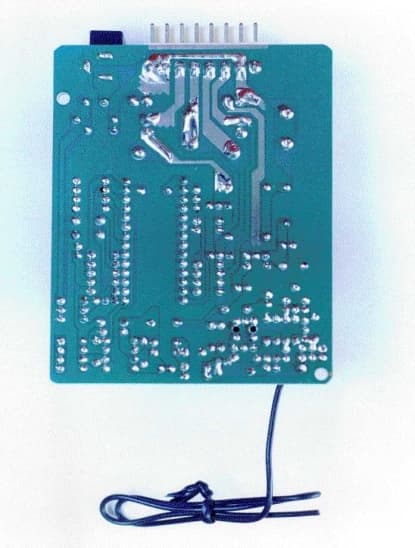
OYT3201218
Dec 06, 2000RF Remote Switch
Equipment Class
CRR - Superregenerative Receiver
OYT-3201219
Jun 19, 2000CRR - Superregenerative Receiver
Equipment Class
CRR - Superregenerative Receiver