OYT3201216RF Remote Switch
AM Equipment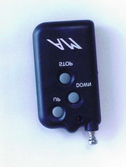
Click to zoom
Application Details
- Equipment Class
- DSC - Part 15 Security/Remote Control Transmitter
- Date of Grant
- Dec 19, 2000
- Application Purpose
- Original Equipment
- Date of Application
- Nov 19, 2000
- Equipment Note
- RF Remote Switch
- Frequency Range
- 311.00000000 - 311.00000000
- Company
- AM Equipment
- Country
- United States
Documents & Files
Document Text
Text extracted from the exhibit documents filed with the FCC. Open a document above to read the original.
Users Manual
Transmitter • • • • • FUNCTION (1) Telescopic ANT (2) LED Lamp Power ON/OFF, While press the button • , • or • , the LED light ON. (3) DATA CODING SWITCH ( • , • and • ) When press the button • , • or • , programmed data automatically connected to receiver. A) If press the switch No.3, the receiver start operation upward. B) If press the switch No.4, the receiver start operation downward. C) If press the switch No.5, the receiver stop operation. Receiver AM UP DOWN STOP SW1 SW2 • • ( Top view ) No.1 connection : DC 12volt No.2 connection : DC 12volt Limit switch (B+) No.3 connection : Limit switch input No.4 connection : DC 12volt output (Motor) No.5 connection : DC 12volt output (Motor) No.6 connection : Limit switch input No.7 connection : DC 12volt Limit switch (B+) No.8 connection : Ground Tact switch 1 : While LED ON, If press the switch No.1, then the LED light OFF Also be added Memory quantity. Tact switch 2 : While press the switch No.2, the LED ON. And press until the LED light OFF, then all memorized code automatically erased. CHARGE JACK : use for 12[V] Battery charger. Caution : Any changes or modifications in construction of this device which are not expressly approved by the party responsible for compliance could void user's authority to operate the equipment. FCC ID : OYT3201218 TRADE NAME : AM-202 MODEL NO.:AM-202 THIS DEVICE COMPLIES WITH PART 15 OF THE FCC RULES. OPERATION IS SUBJECT TO THE FOLLOWING TWO CONDITIONS : (1) THIS DEVICE MAY NOT CAUSE HARMFUL INTERFERENCE, AND (2) THIS DEVICE MUST ACCEPT ANY INTERFERENCE RECEIVED, INCLUDING INTERFERENCE THAT MAY CAUSE UNDESIRED OPERATION. AM EQUIPMENT.CO ADDRESS : 402E.HAZEL JEFFESON.OR 97352 P.O.BOX 790 TEL : 541)327-1546 FAX : 541)327-1548 NAME : TED POWELL
Block Diagram
TRANSMITTER VDD 12[ V] ANTENNA Q1 RF OSCAMPLIFIER AM MOD SIGNAL IC1 TONEDATA CONTROLCONTROL SWI TCHSW1, SW2D1,D2,D3,D4 L1 LOCAL OSC L1 LOCAL OSC
External Photos
External Photos
ID Label/Location Info
ID Label TR ANSM ITTER FCC ID : OYT3201216 TRADE NAME : AM-202 MODEL NO : AM-202 1. Caution is in manual 2. FCC ID,MODEL, and TRADE NAME are in Transmi tter
Internal Photos
Internal Photos
Operational Description
DESCRIPTION OF TRANSMITTER CIRCUIT 1. AM MODULATION Audio frequency which is devided and oscillated by resistor(R3), make operate the base of transistor(Q1). 2. When press the SW1 , SW2 or SW3, ENCODER IC(IC1) oscillate the supplied data. • Make resonate with coil and capacitor(Q1,L1,C3 and C2) first. • Resonated frequency generate wanted frequency by adjust trimmer capaciter (CT1). • And send it to Telescopic ANT
Schematics
TX SCHEMETIC DIAGRAM BATTERY+ R2680 Q1 C1674YC SW3 1 2 BATTERY- C3 4pF R3 1K LED1RED R4 2.2M C5 0.001 C4 3pF SW1 1 2 C1 5pF D2 1N4148 SW2 1 2 L2 2T D1 1N4148 D5-D61N4148 C6 4pF D4 1N4148 U2 24C02B 1 3 2 4 6 5 7 8 1 3 2 4 6 5 7 8 L11.5uH R11M D3 1N4148 C2 4pF
Test Report
KTL Korea Testing Laboratory Page 1 of 14 TEST REPORT This test report only responds to the tested sample and shall not be reproduced except in full without written approval of the Korea Testing Laboratory. Tested and reported by Reviewed by Jeong-Min Kim , Senior Engineer Seok-Jin Kim , EMC Team Leader KOREA TESTING LABORATORY FG101-01-02-00 222-13, Guro-Dong Guro-Gu Seoul Korea 152-053 http://www.ktl.re.kr Ref. Report No. 00-341-051-01 Name and address of the applicant AM Equipme nt P.O. BOX 790 402 E. HAZEL JEFFERSON, OR 97352 U.S.A. Standard / Test regulation FCC Part 15, Subpart C Test result Pass Incoming date : October 12, 2000 Test item( s) ; Security/Re mote Control Transmitter (RF Remote Switch) Model/type ref. ; AM-202 Manufacturer ; U-TEK Engineering Additional information ; -Re quire d Aut ho riz atio n : Ce rtificatio n -FCC ID. : OYT3201216 Test date : November 01, 2000Issue date : November 06, 2000 Ref. Report No. 00-341-051-01 2 Page of 14 TABLE O F CONTENTS I. GENERAL INFORMATION ............................................................................................................ 3 1. Grantee’s Name and Mailing Address 2. Manufacturer's Name and Mailing Address 3. Equipment Descriptions 4. Rules and Regulations 5. Measuring Procedure 6. Date of Measurement α. GENERAL REQUIREMENTS OF THE EUT .................................................................4 1. Labelling Requirement (Section 15.19) 2. Information to User (Sections 15.21) 3. Special Accessories (Section 15.27) 4. Compliant Conditions (Section 15.231) β. RADIATED EMISSION MEASUREMENT (Section 15.231) .......................................................6-12 1. Test Procedure 2. Photograph of the test configuration 3. Sample Calculation 4. Measurement Data 5. Reference Data χ. OCCUPIED BANDWIDTH MEASUREMENT (Section 15.231).................................................13 δ. TEST EQUIPMENTS USED FOR MEASUREMENT..................................................................14 Ref. Report No. 00-341-051-01 3 Page of 14 . GENERAL INFORMATION 1. Grantee’s Name and : AM Equipment Mailing Address P. O. Box 790, 402 E. HAZEL JEFFERSON, OR 97352 U.S.A. 2. Manufacturer's Name and: U-TEK Engineering Mailing Address 2-237, Ichon Ind. Goods Center 129, Songhyun-Dong, Dong-Gu, Inchon, Korea 401-040 3. Equipment Descriptions 3.1 Operating Frequency : 311 MHz 3.2 Type of Emission : Pulse Code Signal 3.3 Oscillator Used: 311 MHz (Resonator) 3.4 Power Supply: DC 12V(Battery) 4. Rules and Regulations: FCC Part 15, Subpart C 5. Measuring Procedure: ANSI C63.4-1992 6. Date of Measurement 6.1 Line Conducted: Not Applicable 6.2 Radiated Emission : November 01, 2000 Ref. Report No. 00-341-051-01 4 Page of 14 . GENERAL REQUIREMENTS O F THE EUT 1. Labelling Requirement (Section 15.19) This device complies with Part 15 of the FCC Rules. Operation is subject to the following two conditions: (1) this device may not cause harmful interface, and (2) this device must accept any interference received, including interference that may cause undesired operation. 1.1 Location of Label : User’s Guide Manual 1.2 How Applied : Printing 2. Information to User (Section 15.21) The following or similar statements were provided in the manual for user instruction. Please refer page 2 of the attached manual for details. CA UT ION : A ny c ha nges or modifications i n cons truc tion o f this device w hich are not e xpressly approved by the party responsible for compliance could void the user's authority to operate the equipment. 3. Special Accessories (Section 15.27) 3.1 Were the special Accessories provided? [ ] yes, [ x ] no 3.2 If yes, details for the special accessories are as follows : 3.3 If yes, were the appropriate instructions provided on the first page of the text concerned with the device? [ ] yes, [ ] no 3.4 Are these accessories provided of the type which can be readily obtained from multiple retail outlets ? [ ] yes, [ ] no And therefore does the manual specify what additional components or accessories are required to used in order to comply with the Rules? [ ] yes, [ ] no Ref. Report No. 00-341-051-01 5 Page of 14 4. Compliant Conditions (Section 15.231) 4.1 Was the EUT used for continuous transmissions, such as voice or video, and data transmission ? [ ] yes, [ x ] no 4.2 Was the EUT manually operated ? [ x ] yes, [ ] no If yes, did the EUT employ a switch that would automatically deactivate the transmitter within not more than 5 seconds of being released ? [ x ] yes, [ ] no 4.3 Was the EUT automatically activated ? [ ] yes, [ x ] no If yes, did the EUT cease transmission within 5 seconds after deactivation ? [ ] yes, [ ] no 4.4 Was the EUT used for periodic transmissions at regular predetermined intervals ? [ ] yes, [ x ] no Ref. Report No. 00-341-051-01 6 Page of 14 . RADIATED EMISSION MEASUREMENT (Section 15.231) 1. Test Procedure 1.1 Preliminary Testing for Reference Preliminary testing was performed in a KTL absorber-lined room to determine the emission characteristics of the EUT. The EUT was placed on the wooden table which has dimensions of 0.8 meters in height, 1 meter in length and 1.5 meters in width. Receiving antenna (Biconical antenna : 30 to 300MHz, Log-periodic antenna : 200 to 1000MHz or Horn Antenna : 1 to 18GHz) was placed at the distance of 1 meter from the EUT. An attempt was made to maximize the emission level with the various configurations of the EUT. The position of the EUT was horizontally or vertically changed to find the worst case configuration. Emissions level from the EUT with various configurations were examined on a spectrum analyzer connected with a RF amplifier and graphed by a plotter. 1.2 Final Radiated Emission Test at an Absorber-Lined Room The final measurement of radiated field strength was carried out in a KTL absorber-lined Room that was listed up at FCC according to the "Radiated Emissions Testing" procedure specified by ANSI C63.4. Based on the test results in preliminary test, …
Text truncated - open the document above for the full version.
Contact Information
Applicant
Ted Powell(President)
Test Firm
Korea Testing LaboratoryJeong-Min Kim
Technical Specifications
| # | Rule Parts | Frequency Range | Power Output |
|---|---|---|---|
| 1 | 15C | 311 MHz - 311 MHz | - |
Other Applications from AM Equipment
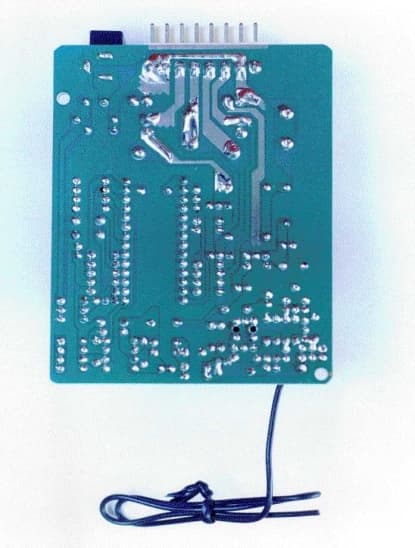
OYT3201218
Dec 06, 2000RF Remote Switch
Equipment Class
CRR - Superregenerative Receiver
OYT-3201219
Jun 19, 2000CRR - Superregenerative Receiver
Equipment Class
CRR - Superregenerative Receiver
OYT-3201220
Jun 19, 2000RF Motor Control System
Equipment Class
DSC - Part 15 Security/Remote Control Transmitter