OZ3HC401SLighting Control Switch (Motion sensor)
Hytronik Electronics Co., Ltd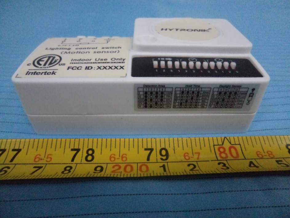
Click to zoom
Application Details
- Equipment Class
- FDS - Part 15 Field Disturbance Sensor
- Date of Grant
- Aug 02, 2012
- Application Purpose
- Original Equipment
- Date of Application
- Aug 02, 2012
- Equipment Note
- Lighting Control Switch (Motion sensor)
- Frequency Range
- 5808.10000000 - 5808.10000000
- Country
- China
Documents & Files
Document Text
Text extracted from the exhibit documents filed with the FCC. Open a document above to read the original.
Users Manual
Hytronik Industrial Ltd. www.hytronik.com Tel: 86-755-27322200 Fax: 86-755-27308687 User Manual of Microwave Motion Sensor Standard version Model no.: HC401S Technical Specifications PRODUCT TYPE: Microwave Motion Sensor OPERATING VOLTAGE: 120-277VAC 60Hz HF SYSTEM: 5.8GHz ±15MHz TRANSMISSION POWER: <1mW RATED LOAD: 120VAC(400W) 277VAC(1000W)(capacitive load) DETECTION ANGLE: ≤150°(without glass louvre) POWER CONSUMPTION: <1W DETECTION RANGE: 1-16 meters in diameter, adjustable TIME SETTING: 10s ~ 30 min. MOUNTING: Indoors, ceiling & walling mounted LIGHT CONTROL: 5 ~ 50LUX/disable Working temperature: -20~ 70°C The sensor is an active motion detector; it emits a high-frequency electro- magnetic wave 5.8GHz and receives its echo. The sensor detects the change in echo from movement in its detection zone. A microprocessor then triggers the switch light ON command. Detection is possible through doors, panels of glasses thin walls. NOTE: the high-frequency output of this sensor is <1mW; approximately just 1% of the transmission power of a mobile telephone or the output of a microwave oven. IMPORTANT PLEASE READ THESE INSTRUCTIONS CAREFULLY PRIOR TO INSTALLATION AND RETAIN THIS LEAFLET IN A KNOWN AND SAFE PLACE FOR FUTURE REFERENCE. SECTION 1 INSTALLATION & WIRING 2.0 ENSURE THAT THE ELECTRICITY SUPPLY IS SWITCHED OFF COMPLETELY BEFORE INSTALLING OR SERVICING THIS PRODUCT The sensor works with a main voltage of 120-277VAC 60Hz. The sensor has a 4-wire electrical interface: N (neutral / 120-277V AC) L (phase / 120-277 V AC) L’ (switched phase / output) To connect standard ballast with sensor To connect Hytronik sensorDIM ballast with sensor (ON-OFF function), the wiring should be: the wiring should follow the below schematic: Hytronik Industrial Ltd. www.hytronik.com Tel: 86-755-27322200 Fax: 86-755-27308687 2.1 This sensor is suitable for indoor use, and is also designed for installation at max. 4 meters in height. * While sensor use with Hytronik sensorDIM ballast or other dimming ballast, please keep the sensor antenna module from the ballast and lamp filament by at least 80mm. SECTION 2 SETTINGS Detection range: This determines the effective range of the motion detector and is set by DIP switches at the sensor itself, refer to figure. Note that reducing the sensitivity will also narrow the detection range. The following settings are available: I - Detection range 100% II – Detection range 75% III – Detection range 50% IV – Detection range 25% V – Detection range 10% Hold time: This determines the time the fitting remains at 100% level on motion detection and is set with DIP switches at the sensor itself, refer to figure. The walk test setting is useful when installing the fitting to establish correct operation and range. The following settings are available: I – 30 minutes II – 20 minutes III – 6 minutes IV – 90S V – 30S VI – 10S Daylight sensor: This setting holds off the 100% light output should there sufficient daylight and is set using DIP switches at the sensor, refer to figure. The following settings are available: I – Photocell disabled II – 50 lux daylight operation III – 30 lux daylight operation IV – 10 lux twilight operation V – 5 lux darkness operation only *In daylight setting the lamp(s) will always be on with motion detected and operate at 100% light output, even in bright daylight. SECTION 3 TROUBLE SHOOTING MALFUNCTION CAUSE REMEDY CAUSE REMEDY The load will not work Incorrect light-control setting selected Adjust setting Load faulty Replace load Mains switch OFF Switch ON The load is always on Continuous movement in the detection zone Check zone setting The load is on without any identifiable movement The sensor is not mounted for reliably detecting movement Securely mount enclosure Movement occurred, but not identified by the sensor (movement behind wall, movement of small object in immediate lamp vicinity etc.) Check zone setting The load will not work despite movement Rapid movements are being suppressed to minimize malfunctioning or the detection radius is too small Check zone setting FCC Caution Any Changes or modifications not expressly approved by the party responsible for compliance could void the user’s authority to operate the equipment. This device complies with part 15 of the FCC Rules. Operation is subject to the following two conditions: (1) This device may not cause harmful interference, and (2) this device must accept any interference received, including interference that may cause undesired operation.
Cover Letter(s)
@ HYfRONIK Hydrim Electronics Co.,Ltd Block 46 Haosi Linpo Keng Ind.Park Shajing Town Bao'an District Shenzhen P.R.C FEDERAL COMMLINICATIONS COMMISSIONS " Authorization and Evaluation Division 7435 Oakland Mills Road Columbia, MD 21046 Confidentiality Request regarding application for certification of FCC ID: OZ3HC401S Pursuant to Sections 0.457 and 0.459 of the Commission's Rules, we hereby request eonfidential treatment of information accompanying this application as outlined below: Detailed Circuit Schematics of EUT--- (Long term) Block Diagram--- (Long term Part List---(Long term) The above materials contain trade secrets and proprietary information not customarily released to the public. The public disclosure of these materials may be harmful to the applicant and provide unjustified benefits to its competitors. The applicant understands that pursuant to Section 0.457 of the Rules, disclosure of this application and all accompanying documentation will not be made before the date of the Grant for this application.
External Photos
EXHIBIT B - EUT EXTERNAL PHOTOGRAPHS EUT – Top View EUT – Side View 1 EUT – Side View 2
ID Label/Location Info
EXHIBIT A - FCC ID LABELING AND LOCATION FCC ID Label FCC ID Label Location The label shown shall be permanently affixed at a conspicuous location on the device and be readily visible to the user at the time purchase (Labeling requirements per 2.925)
Internal Photos
EXHIBIT C - EUT INTERNAL PHOTOGRAPHS EUT – Cover off View 1 EUT – Cover off View 2 EUT – Main Board Top View EUT – Main Board BottomView
Test Report
Note: This test report is prepared for the customer shown above and for the device described herein. It may not be duplicated or used in part without prior written consent from Bay Area Compliance Laboratories Corp. (Shenzhen). This report must not be used by the customer to claim product certification, approval, or endorsement by NVLAP*, or any agency of the Federal Government. * This report contains data that are not covered by the NVLAP accreditation and are marked with an asterisk “★” (Rev.2) FCC PART 15.245 MEASUREMENT AND TEST REPORT For Hydrim Electronics Co., Ltd. Block A6 Haosi Linpo Keng Ind.Park Shajing Town Bao’an District Shenzhen P.R.C FCC ID: OZ3HC401S Report Type: Original Report Product Type: Lighting Control Switch (Motion sensor) Test Engineer: Tiger Ye Report Number: RSZ120723002-00 Report Date: 2012-08-02 Reviewed By: Alvin Huang RF Leader Test Laboratory: Bay Area Compliance Laboratories Corp. (Shenzhen) 6/F, the 3rd Phase of WanLi Industrial Building, ShiHua Road, FuTian Free Trade Zone Shenzhen, Guangdong, China Tel: +86-755-33320018 Fax: +86-755-33320008 www.baclcorp.com.cn Bay Area Compliance Laboratories Corp. (Shenzhen) Report No.: RSZ120723002-00 FCC Part 15.245 Page 2 of 19 TABLE OF CONTENTS GENERAL INFORMATION.......................................................................................................................................3 PRODUCT DESCRIPTION FOR EQUIPMENT UNDER TEST (EUT) .....................................................................................3 OBJECTIVE...................................................................................................................................................................3 RELATED SUBMITTAL(S)/GRANT(S).............................................................................................................................3 TEST METHODOLOGY..................................................................................................................................................3 TEST FACILITY.............................................................................................................................................................3 SYSTEM TEST CONFIGURATION ..........................................................................................................................5 JUSTIFICATION.............................................................................................................................................................5 EQUIPMENT MODIFICATIONS.......................................................................................................................................5 LOCAL SUPPORT EQUIPMENT LIST AND DETAILS........................................................................................................5 BLOCK DIAGRAM OF TEST SETUP................................................................................................................................5 SUMMARY OF TEST RESULTS...............................................................................................................................6 FCC§15.203 - ANTENNA REQUIREMENT..............................................................................................................7 APPLICABLE STANDARD..............................................................................................................................................7 ANTENNA CONNECTOR CONSTRUCTION......................................................................................................................7 FCC §15.207 (A) – AC LINE CONDUCTED EMISSIONS ......................................................................................8 APPLICABLE STANDARD..............................................................................................................................................8 MEASUREMENT UNCERTAINTY....................................................................................................................................8 EUT SETUP..................................................................................................................................................................8 EMI TEST RECEIVER SETUP.........................................................................................................................................9 TEST PROCEDURE........................................................................................................................................................9 TEST EQUIPMENT LIST AND DETAILS...........................................................................................................................9 TEST RESULTS SUMMARY............................................................................................................................................9 TEST DATA..................................................................................................................................................................9 FCC§15.205, §15.209&§15.245(B) - RADIATED EMISSIONS ..............................................................................14 APPLICABLE STANDARD............................................................................................................................................14 MEASUREMENT UNCERTAINTY..................................................................................................................................15 TEST EQUIPMENT SETUP............................................................................................................................................15 EUT SETUP................................................................................................................................................................15 TEST PROCEDURE......................................................................................................................................................16 CORR…
Text truncated - open the document above for the full version.
Test Setup Photos
EXHIBIT D - TEST SETUP PHOTOGRAPHS Conducted Emissions - Front View Conducted Emissions - Side View Below 1 GHz: Radiated Emissions View Above 1 GHz: Radiated Emissions View
Contact Information
Applicant
Qinqin Yin
Test Firm
Bay Area Compliance Laboratory Corp. (Shenzhen)John Chan
Technical Specifications
| # | Rule Parts | Frequency Range | Power Output |
|---|---|---|---|
| 1 | 15.245 | 5.81 GHz - 5.81 GHz | - |
Other Applications from Hytronik Electronics Co., Ltd
OZ3HC428VRF
May 28, 2015Lighting Control Switch
Equipment Class
DXT - Part 15 Low Power Transceiver, Rx Verified
OZ3HC418VRF
May 28, 2015Lighting Control Switch
Equipment Class
DXT - Part 15 Low Power Transceiver, Rx Verified
OZ3HFM-01
Apr 09, 2014HF-MODULE
Equipment Class
FDS - Part 15 Field Disturbance Sensor
OZ3HC430S
Aug 02, 2012Lighting Control Switch (Motion sensor)
Equipment Class
FDS - Part 15 Field Disturbance Sensor