OZ3HC418VRFLighting Control Switch
Hytronik Electronics Co., Ltd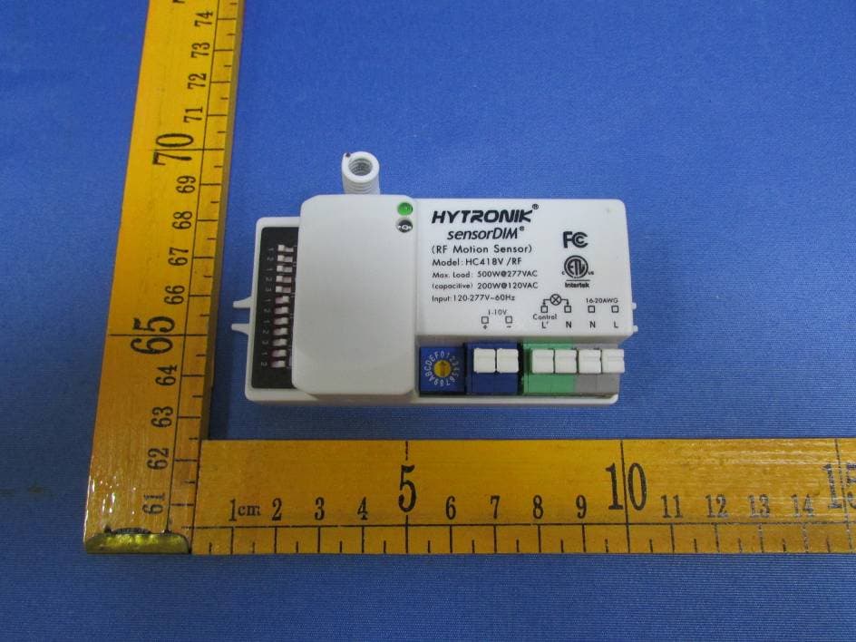
Click to zoom
Application Details
- Equipment Class
- DXT - Part 15 Low Power Transceiver, Rx Verified
- Date of Grant
- May 28, 2015
- Application Purpose
- Original Equipment
- Date of Application
- May 28, 2015
- Equipment Note
- Lighting Control Switch
- Frequency Range
- 915.00000000 - 915.00000000
- Country
- China
Documents & Files
Document Text
Text extracted from the exhibit documents filed with the FCC. Open a document above to read the original.
Users Manual
120~277VAC 60Hz. Model NO.:HC418V/RFModel NO.:HC424RF RF antenna Rotary coding switch Stand-by period Stand-by dimming level Detection area Daylight threshold Stand-by period Stand-by dimming level Hold-time Rotary coding switch RF Antenna LED indication Daylight sensor Block A6, Nan’pu Science & Technology Park, Hao’si, Shajing Street, Bao’an District, Shenzhen, P.R.C. 518104 T: 86 755 27322200 F: 86 755 27308687 E: [email protected] W: www.hytronik.com HYTRONIK ELECTRONICS CO.,LTD 2.2 Keep the RF antenna at least 3cm away from the driver or ballast. 1.4 2.1 Ensure that the electricity supply is switched off completely before installing or servicing this product. PROTECTION LEVEL STANDBY PERIOD STANDBY DIMMING LEVEL WORKING TEMPERATURE HC418V/RF Up to 30 meters indoor transmission and 100 meters in open area. Fixed address coding with 10 channels (max. 10 groups) Diameter Max. 12m 5s~30min -20 ~ +60°C 0s, 10s~1h, +0s, 10s~1h, + 10~50%10~50% -20 ~ +60°C Max. 6mMax. 6m HC424RF 120~277VAC 60Hz 120~277VAC 60Hz 200W@120VAC; 500W@277VAC(capatitive Load) Wring with any 1~10V control gear to achieve dimming function. HC418V/RF LED Driver LED Driver HC424RF RF wireless communication makes installation easier with no cables connection.The motion at 1 sensor (the master unit) can be passed onto other pre-defined individuals (the slave units) through RF transmission. This wireless radio wave transmission can reach 100 meters in open area with internal RF antenna, 30 meters blocked by one wall, 20 meters blocked by two walls. Settings for HC418V/RF I – 5S II – 30S III – 1 minute IV – 5 minutes V – 10 minutes VI – 20 minutes VII – 30 minutes I – Disable II – 50 lux III – 10 lux IV – 2 lux I – maximum range up to 100% II – 75% III – 50% IV – 10% I – 0S II – 10S III – 1 minute IV – 5 minutes V – 10 minutes VI – 30 minutes VII – 1 hour VIII – + Note: “0s” means on/off control; “+∞” means 2 steps of dimming control, fixture never switch off. ∞ +∞ This is the time period you would like to keep at the low light output level before it is completely switched off in the long absence of people. Stand-by period (corridor function) I – 10% II – 20% III – 30% IV – 50% This is the dimmed low light output level you would like to have after the hold-time in the absence of people. Stand-by dimming level 100% 75% 50% 10% 1 2 I II III IV I II III IV V VI VII 1 2 3 5S 30S 1min 5min 10min 20min 30min I II III IV Disable 50 lux 10 lux 2 lux 1 2 0S 10S 1min 5min 10min 30min 1h I II III IV V VI VII VIII 1 2 3 10% 20% 30% 50% I II III IV 1 2 This determines the time the fitting remains at 100% level on motion detection and is set sith DIP swiches at the sensor itself, refer to figure. The walk test seing is useful when installing the fitting to establish correct operation and range. The following settings are available: Hold time: Daylight sensor: This settingholdsoff the 100% light output shouldthere sufficientdaylight andis set usingDIPswitches at the sensor, refer to figure. The following settings are available: Detection Area: This determines the effective range of the motion detector and is set by DIP switches at the sensor itself, refer to figure. Note that reducing the sensitivity will also narrow the detection range.The following settings are available: *In disable mode the lamp(s) will always be on with motion detected and operate at 100% light output, even in bright daylight. I – 10% II – 20% III – 30% IV – 50% Settings for HC424RF Stand-by period (corridor function) This is the time period you would like to keep at the low light output level before it is completely switched off in the long absence of people. I – 0S II – 10S III – 1 minute IV – 5 minutes V – 10 minutes VI– 30 minutes VII– 1 hour VIII– +∞ +∞ 0S 10S 1min 5min 10min 30min 1h I II III IV V VI VII VIII 1 2 3 Stand-by dimming level This is the dimmed low light output level you would like to have after the hold-time in the absence of people. 10% 20% 30% 50% I II III IV 1 2 RF grouping (max. 10 channels) Using a screwdriver to adjust the rotary switch on both the master & slave unit, to keep them pointing at the same channel, the grouping is then automatically completed. 10 channels (max. 10 groups) available for both the master & slave unit. Using a screwdriver to point the arrow to the same position on the master unit and slave units. master slave SECTION 4 RF GROUPING SECTION 5 FUNCTIONS 5.1 100H burn-in mode for fluorescent lamp With simple operation, rapidly turn off/on the fixture 3 cycles wihin 3 sec. (the green LED on the sensor flashes and the fixture blinks 3 times to indicate the success of setup), lamp will be 100% on for 100 hours, and then automatically goes to sensor mode after 100 hours. This is crucial to secure the lifetime of fluorescent lamp, when new fixture is installed,or old lamp is replaced. This 100h burn-in feature can be cancelled by turn off/on the fixture 1 cycle within 1 sec. With simple operation, rapidly turn off/on the fixture 2 cycles within 2 sec: a. the green LED on the sensor flashes slowly for 5 seconds, meanwhile the fixture blinks twice. b. the daylight sensor measures and remembers the surrounding lux for 1 sec. c. the fixture and green LED is on for 10s to indicate the success of learning. 5.2 Ambient daylight threshold This feature enables the fixture to function well in any real application circumstance, where the daylight penetrated into fixture may vary a lot. The latest surrounding lux value overwrites previous lux value learned. Both the setting on DIP switch and the learned ambient lux threshold can overwrite each other.The latest action stays in validity. * * * Note: “0s” means on/off control; “+∞” means 2 steps of dimming control, fixture never switch off. Designed in the software, the sensor switches on/off the load right on the zero-cross point, to ensure the min. current passing through the relay contact point, and enable the max. load and life-time of the relay. 5.3 Zero-cross relay operation Double L…
Text truncated - open the document above for the full version.
Cover Letter(s)
Hytronik Electronics Co.,Ltd. Date: Apr. 29, 2015 Federal Communications Commission Authorization and Evaluation Division Confidentiality Request regarding application for certification of FCC ID: OZ3HC418VRF Pursuant to Sections 0.457 and 0.459 of the Commission’s Rules, we hereby request confidential treatment of information accompanying this application as outlined below: Exhibit Type File Name Schematics Block Diagram Operational Description SCH.pdf BlockDiagram.pdf Operational Description.pdf The above materials contain trade secrets and proprietary information not customarily released to the public. The public disclosure of these materials may be harmful to the applicant and provide unjustified benefits to its competitors. The applicant understands that pursuant to Section 0.457 of the Rules, disclosure of this application and all accompanying documentation will not be made before the date of the Grant for this application. Sincerely, Hytronik Electronics Co.,Ltd. ................................................ Signature Yin Qinqin / Manager ................................................ Typed name and Title
Cover Letter(s)
Hytronik Electronics Co.,Ltd. FCC ID: OZ3HC418VRF POWER OF ATTORNEY Date: Apr.29, 2015 Federal Communications Commission Authorization and Evaluation Division 7435 Oakland Mills Road Columbia, MD 21046 To Whom It May Concern: We, the undersigned, hereby authorize Waltek Services (ShenZhen) Co., Ltd. (Philo Zhong) on our behalf, to apply to the Federal Communications Commission on our equipment. Any and all acts carried out by Waltek Services (ShenZhen) Co., Ltd. (Philo Zhong) on our behalf shall have the same effect as acts of our own. This authorization expires on Apr 28,2016. This is to advise that we are in full compliance with the Anti-Drug Abuse Act. We, Hytronik Electronics Co.,Ltd. are not subject to a denial of federal benefits pursuant to Section 5301 of the Anti-Drug Act of 1988, 21 USC853a, and no party to the application is subject to a denial of federal benefits pursuant to that section. Sincerely, Hytronik Electronics Co.,Ltd. ................................................................................. Signature Yin Qinqin / Manager ................................................................................. Typed name and Title
External Photos
Waltek Services (Shenzhen) Co.,Ltd. http://www.waltek.com.cn Photographs - Constructional Details HC418V/RF External View Waltek Services (Shenzhen) Co.,Ltd. http://www.waltek.com.cn Waltek Services (Shenzhen) Co.,Ltd. http://www.waltek.com.cn
ID Label/Location Info
FCC Label Location for model: HC418V/RF The Label must not be a stick-on paper. The Label on these products must be permanently affixed to the product and readily visible at the time of purchase and must last the expected lifetime of the equipment not be readily detachable. FCC ID: OZ3HC418VRF This device complies with part 15 of the FCC Rules. Operation is subject to the following two conditions: (1) This device may not cause harmful interference, and (2) this device must accept any interference received, including interference that may cause undesired operation.
ID Label/Location Info
FCC Label Sample for model: HC418V/RF FCC ID: OZ3HC418VRF This device complies with part 15 of the FCC Rules. Operation is subject to the following two conditions: (1) This device may not cause harmful interference, and (2) this device must accept any interference received, including interference that may cause undesired operation.
Internal Photos
Waltek Services (Shenzhen) Co.,Ltd. http://www.waltek.com.cn HC418V/RF Internal View Waltek Services (Shenzhen) Co.,Ltd. http://www.waltek.com.cn 915MHz ANT 5.8GHz ANT Waltek Services (Shenzhen) Co.,Ltd. http://www.waltek.com.cn Waltek Services (Shenzhen) Co.,Ltd. http://www.waltek.com.cn Waltek Services (Shenzhen) Co.,Ltd. http://www.waltek.com.cn Waltek Services (Shenzhen) Co.,Ltd. http://www.waltek.com.cn
Test Report
TEST REPORT Waltek Services (Shenzhen) Co.,Ltd. http://www.waltek.com.cn Page 1 of 28 Reference No. .................... : WTS15S0425543E FCC ID ................................ : OZ3HC418VRF Applicant ............................ : Hytronik Electronics Co.,Ltd. Address .............................. : BlockA6,Haosi Linpo keng Ind.Park Shajing Town Ban’an Distri ct Shen zhen P.R.C Manufacturer .................... : Hytronik Electronics Co.,Ltd. Address .............................. : BlockA6,Haosi Linpo keng Ind.Park Shajing Town Ban’an District Shen zhen P.R.C Product Name .................... : Lighting Control Switch Model No. ........................... : HC418V/RF Standards........................... : FCC CFR47 Part 15 Section 15.249: 2014 Date of Receipt sample .... : Apr. 23, 2015 Date of Test ....................... : Apr. 24 ~ May.14, 2015 Date of Issue ...................... : May.15, 2015 Test Result ......................... : Pass Remarks: The re sults shown in this test report refer only to the sample(s) tested, this test report cannot be reproduced, except in full, without prior written permission of the company. The report would be invalid without specific stamp of test institute and the signatures of compiler and approver. Prepared By: Waltek Services (Shenzhen) Co., Ltd. Address: 1/F., Fukangtai Building, West Baima Road, Songgang Street, Baoan District, Shenzhen, Guangdong, China Tel :+86-755-83551033 Fax:+86-755-83552400 Compiled by: Approved by: Zero Zhou / Project Engineer Philo Zhong / Manager Reference No.: WTS15S0425543E Page 2 of 28 Waltek Services (Shenzhen) Co.,Ltd. http://www.waltek.com.cn 2 Test Summary Test Items Test Requirement Result Conducted Emissions 15.207 PASS Radiated Emission 15.249(a) 15.209 15.205(a) PASS Periodic Operation 15.35(c) PASS Outside of Band Emission 15.249 15.205 15.209 PASS 20dB Bandwidth 15:215(c) PASS Antenna Requirement 15.203 PASS Reference No.: WTS15S0425543E Page 3 of 28 Waltek Services (Shenzhen) Co.,Ltd. http://www.waltek.com.cn 3 Contents Page 1 COVER PAGE ........................................................................................................................................... 1 2 TEST SUMMARY .................................................................................................................................................. 2 3 CONTENTS ............................................................................................................................................................ 3 4 GENERAL INFORMATION .................................................................................................................................. 4 4.1 GENERAL DESCRIPTION OF E.U.T. ............................................................................................................ 4 4.2 DETAILS OF E.U.T. ..................................................................................................................................... 4 4.3 TEST FACILITY ............................................................................................................................................ 4 5 EQUIPMENT USED DURING TEST .................................................................................................................. 5 5.1 EQUIPMENTS LIST ...................................................................................................................................... 5 5.2 MEASUREMENT UNCERTAINTY ................................................................................................................... 5 5.3 TEST EQUIPMENT CALIBRATION ................................................................................................................ 5 6 CONDUCTED EMISSION .................................................................................................................................... 6 6.1 E.U.T. OPERATION .................................................................................................................................... 6 6.2 EUT SETUP ................................................................................................................................................ 6 6.3 MEASUREMENT DESCRIPTION ................................................................................................................... 6 6.4 TEST RESULT ............................................................................................................................................. 7 7 RADIATION EMISSION TEST ............................................................................................................................ 9 7.1 EUT OPERATION ........................................................................................................................................ 9 7.2 TEST SETUP ............................................................................................................................................. 10 7.3 SPECTRUM ANALYZER SETUP ................................................................................................................. 11 7.4 TEST PROCEDURE .................................................................................................................................... 12 7.5 TEST RESULT ........................................................................................................................................... 13 8 PERIODIC OPERATION .................................................................................................................................... 14 9 OUTSIDE OF BAND EMISSION ....................................................................................................................... 15 9.1 TEST PROCEDURE .................................................................................................................................... 15 9.2 TEST RESULT ................................................................…
Text truncated - open the document above for the full version.
Test Setup Photos
Waltek Services (Shenzhen) Co.,Ltd. http://www.waltek.com.cn Photographs- HC418V/RF Test Setup P hotograph – Conducted Emission Test Setup Radiation Emission From 30MHz-1GHz Test Site2# Waltek Services (Shenzhen) Co.,Ltd. http://www.waltek.com.cn Radiat ion Emission Above 1GHz Test Site1#
Contact Information
Applicant
Qinqin Yin
Test Firm
Waltek Services(Shenzhen) Co., Ltd.philo zhong
Technical Specifications
| # | Rule Parts | Frequency Range | Power Output |
|---|---|---|---|
| 1 | 15C | 915 MHz - 915 MHz | - |
Other Applications from Hytronik Electronics Co., Ltd
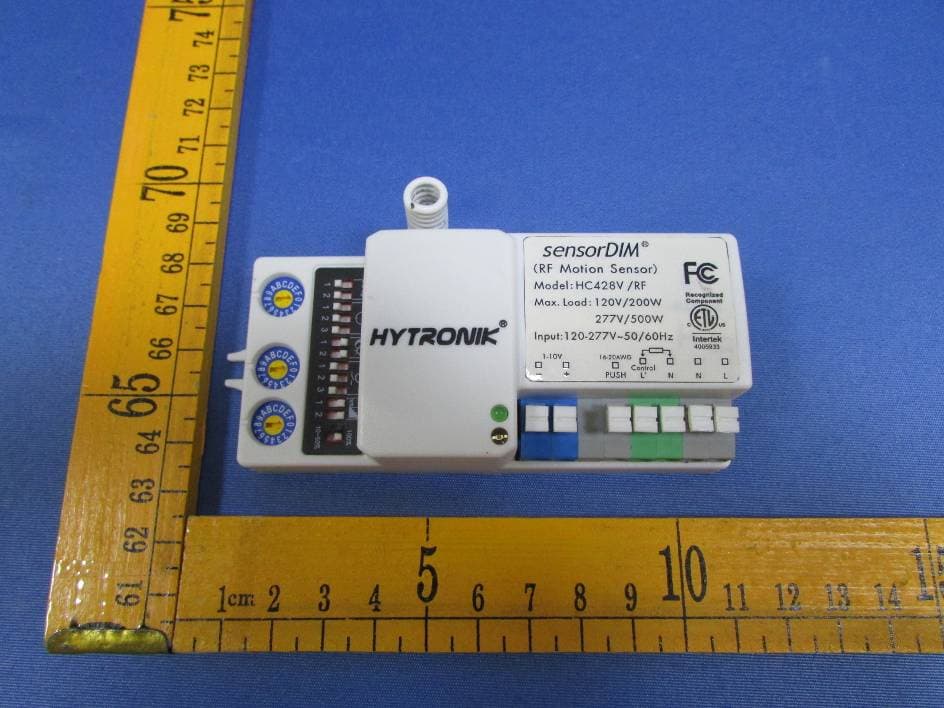
OZ3HC428VRF
May 28, 2015Lighting Control Switch
Equipment Class
DXT - Part 15 Low Power Transceiver, Rx Verified
OZ3HFM-01
Apr 09, 2014HF-MODULE
Equipment Class
FDS - Part 15 Field Disturbance Sensor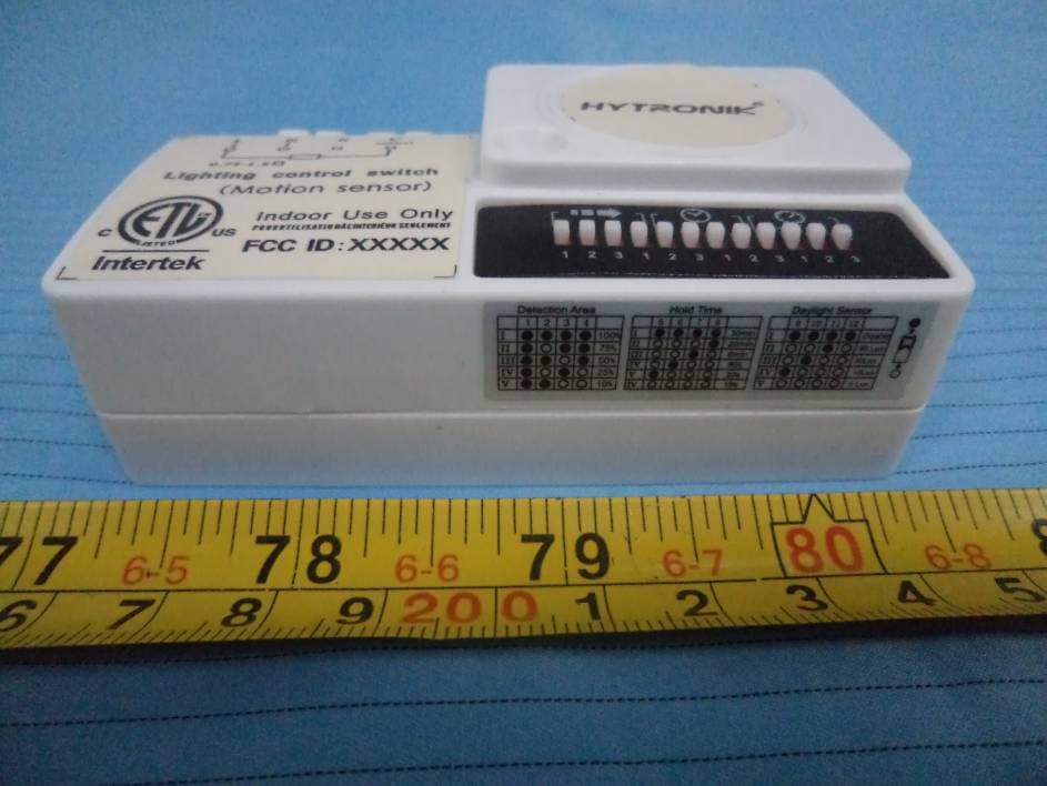
OZ3HC401S
Aug 02, 2012Lighting Control Switch (Motion sensor)
Equipment Class
FDS - Part 15 Field Disturbance Sensor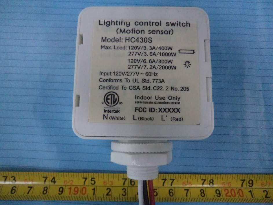
OZ3HC430S
Aug 02, 2012Lighting Control Switch (Motion sensor)
Equipment Class
FDS - Part 15 Field Disturbance Sensor