OZE-RFT-2000Gas Alarm
Gasguard Technologies Inc.
Click to zoom
Application Details
- Equipment Class
- DSC - Part 15 Security/Remote Control Transmitter
- Date of Grant
- May 11, 2000
- Application Purpose
- Original Equipment
- Date of Application
- Apr 24, 2000
- Equipment Note
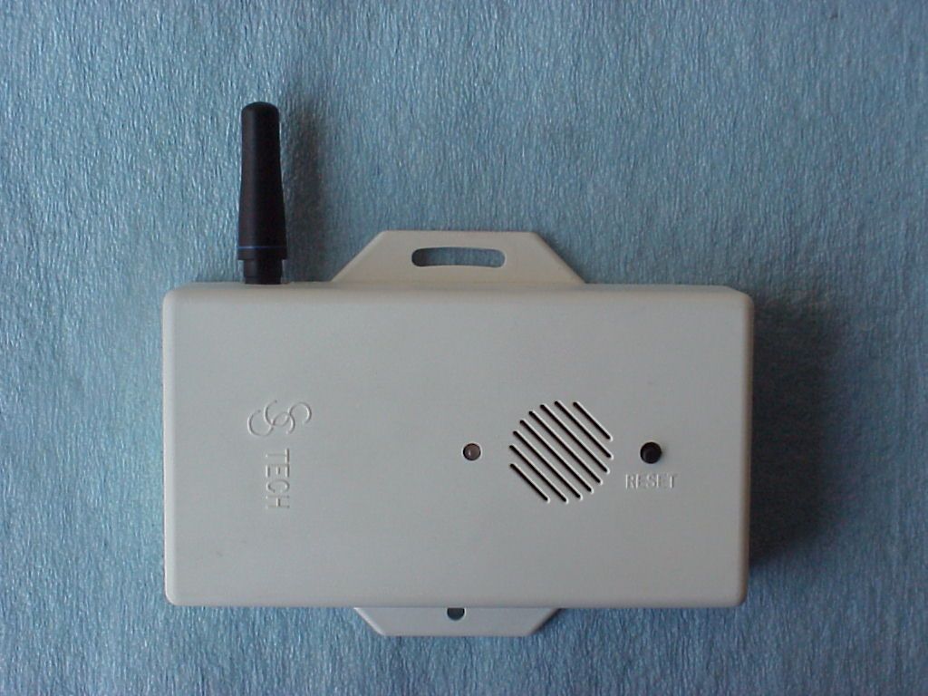
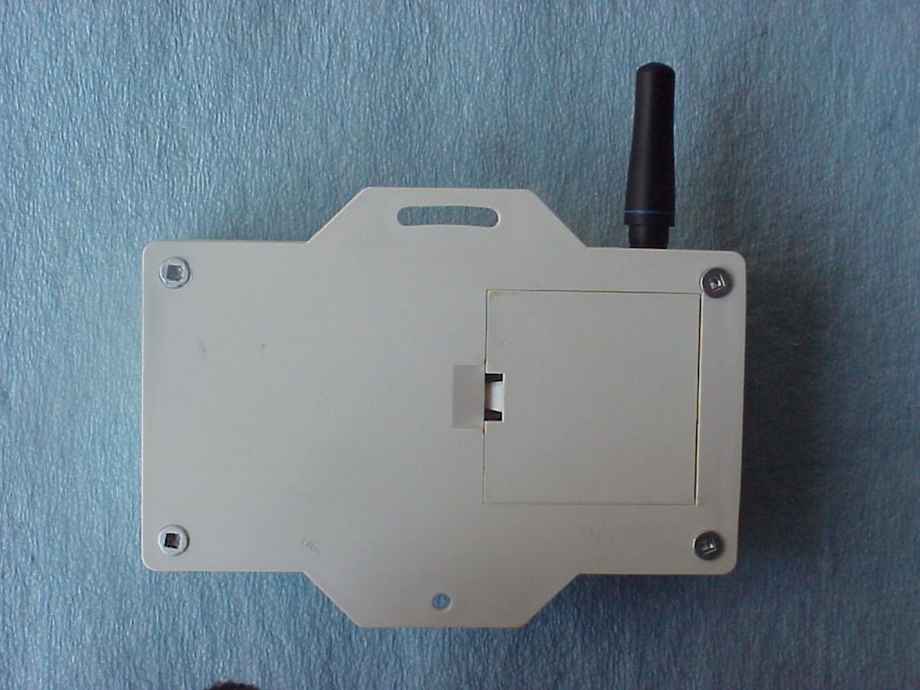
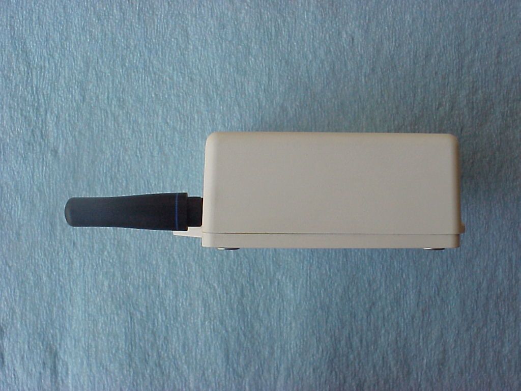
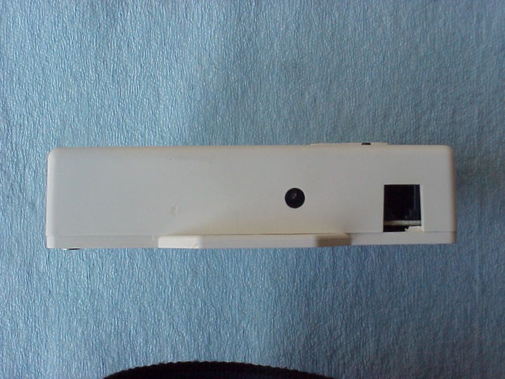
- Gas Alarm
- Frequency Range
- 418.00000000 - 418.00000000
- Company
- Gasguard Technologies Inc.
- Country
- Canada
Documents & Files
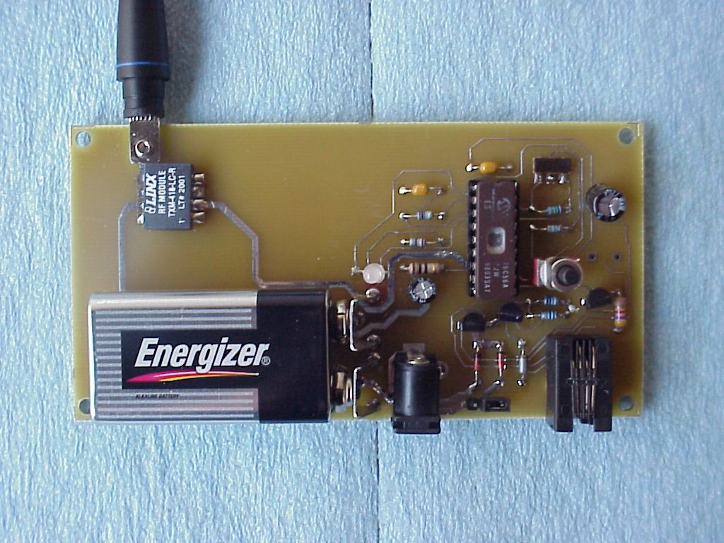
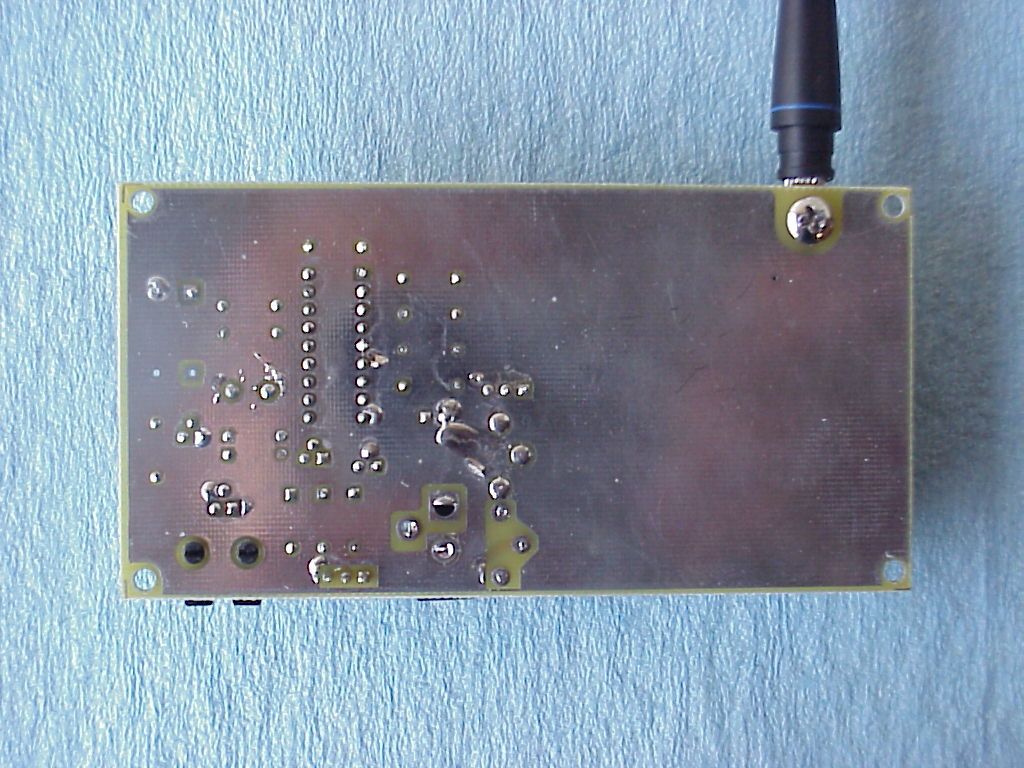
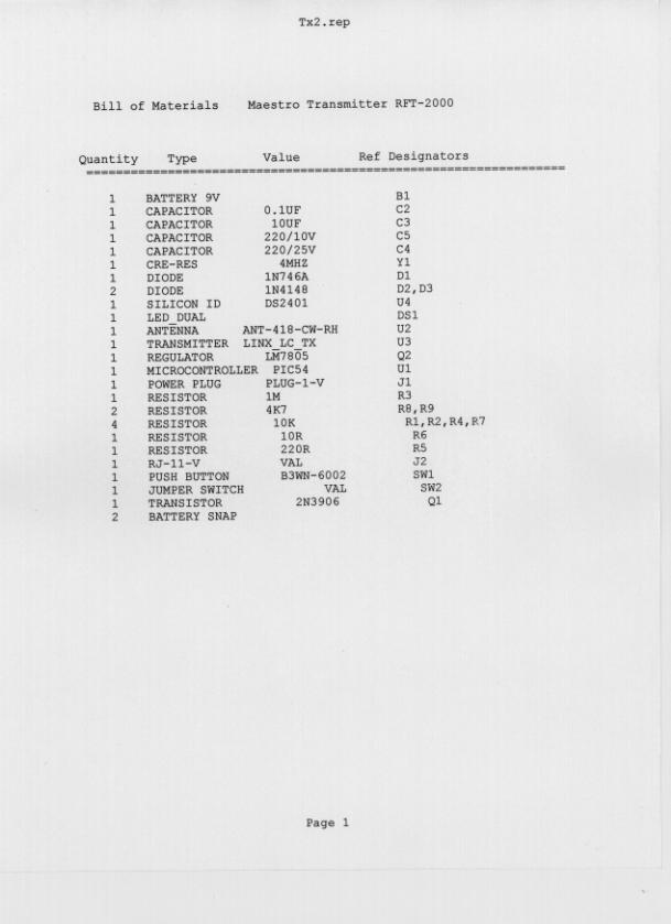
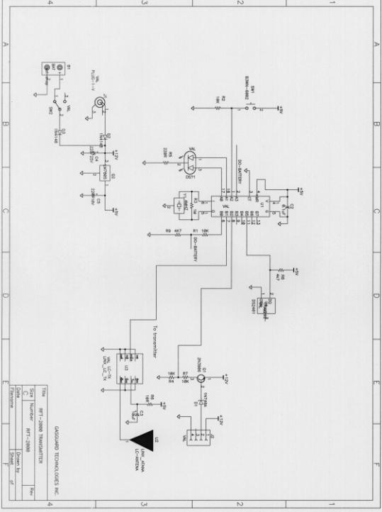
Document Text
Text extracted from the exhibit documents filed with the FCC. Open a document above to read the original.
ID Label/Location Info
FCC ID Label FCC ID: OZE-RFT-2000 Location of Label on the EUT FCC Label Loca ti on
Test Report
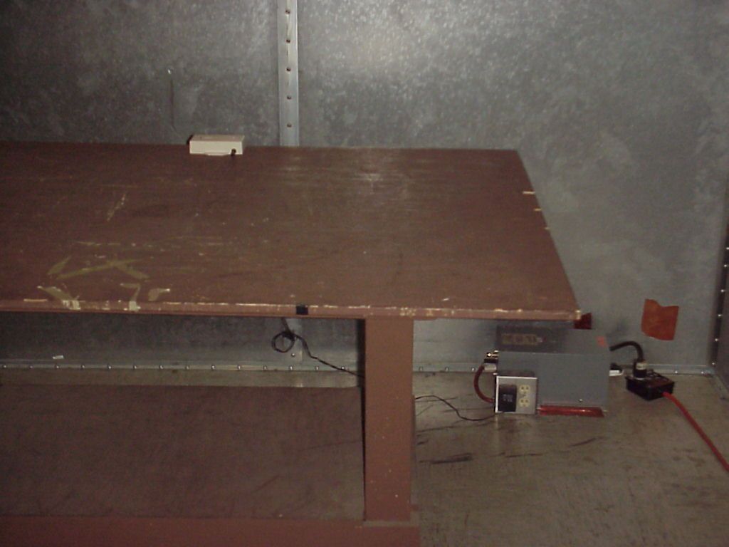
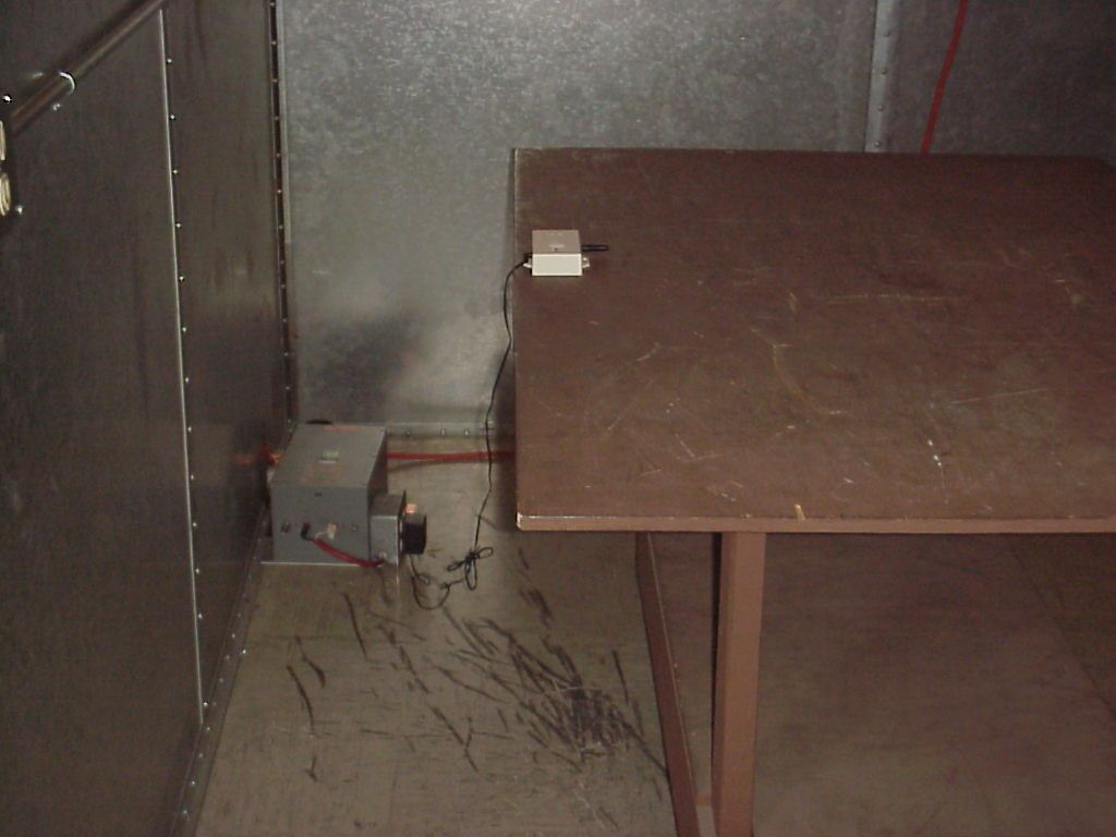
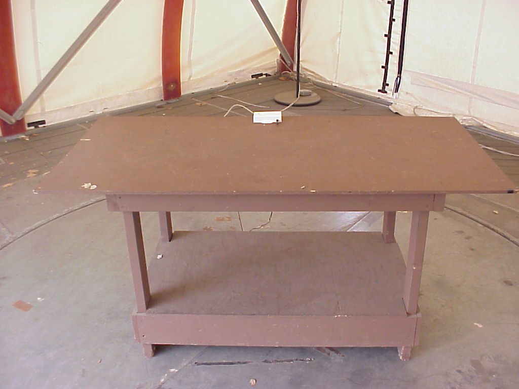
Garwood Laboratories, Inc. Garwood Laboratories, Inc.Garwood Laboratories, Inc. Garwood Laboratories, Inc. - World Compliance Division Electromagnetic Compatibility Document No. FR1407-2EUT: Maestro Transmitter Model RFT-2000Date: 04/20/001 of 31 EMC Measurement / Technical Report FCC Test Specification : Certification for FCC Part 15, Subpart C §15.231 Manufacturer : Gasguard Technologies, Inc. Equipment Under Test : Maestro Transmitter Model RFT-2000 Test Report No. : FR1407-2 Purchase Order No. : 268375 Document History RevisionIssue DateAffected Pages Description of Modifications Revised By Approved By N/C20 April, 2000 Initial release Garwood Laboratories, Inc. Garwood Laboratories, Inc.Garwood Laboratories, Inc. Garwood Laboratories, Inc. - World Compliance Division Electromagnetic Compatibility Document No. FR1407-2EUT: Maestro Transmitter Model RFT-2000Date: 04/20/002 of 31 EMC Measurement / Technical Report Document No. FR1407-2 From Garwood Laboratories, Inc. World Compliance Division Test for Gasguard Technologies, Inc Maestro Transmitter Model RFT-2000 Test PersonnelTest Dates Eric Nguyen – Lead EMC Engineer4 April, 2000 Test Facility Address City, State, Zip Code Phone Fax Garwood Laboratories, Inc. 565 Porter Way Placentia, CA 92870 (714) 572-2027 (714) 572-2025 This report may be reproduced in full, partial reproduction may only be made with the written consent of the laboratory. The results in this report apply only to the equipment tested. This report may not be used to claim product endorsement by NVLAP or any agency of the U.S. government. Garwood Laboratories, Inc. Garwood Laboratories, Inc.Garwood Laboratories, Inc. Garwood Laboratories, Inc. - World Compliance Division Electromagnetic Compatibility Document No. FR1407-2EUT: Maestro Transmitter Model RFT-2000Date: 04/20/003 of 31 TABLE OF CONTENTS (This document contains a total of 31 pages [excluding] attachments.) MEASUREMENT / TECHNICAL REPORT SUMMARY ............................................................................ 4 1. GENERAL INFORMATION................................................................................................................... 5 1.1 Product Description ...................................................................................................... 5 1.2 Related Submittal(s)/ Grant(s) ...................................................................................... 5 1.3 Tested System Description ............................................................................................ 5 1.4 Test Methodology .......................................................................................................... 6 1.5 Test Facility................................................................................................................... 7 2. PRODUCT LABELING.......................................................................................................................... 8 2.1 FCC ID Label................................................................................................................8 2.2 Location of Label on EUT............................................................................................. 8 2.3 Information to the User ................................................................................................. 8 3. SYSTEM TEST CONFIGURATION ....................................................................................................... 9 3.1 Justification ................................................................................................................... 9 3.2 EUT Exercise Software/Equipment ............................................................................... 9 3.3 Special Accessories ....................................................................................................... 9 3.4 Equipment Modifications .............................................................................................. 9 3.5 Configuration of Tested System .................................................................................. 10 3.6 Details of Tested System.............................................................................................. 10 4. BLOCK DIAGRAM(S) OF EUT........................................................................................................... 11 5. TEST MEASUREMENT AND EUT PHOTOS ..................................................................................... 12 6. TEST DATA .......................................................................................................................................... 21 6.1 Conducted Emissions Limits ....................................................................................... 21 6.2 Conducted Emissions Results...................................................................................... 21 6.3 General Radiated Emissions Requirements ................................................................ 22 6.4 General Radiated Emissions Results........................................................................... 22 6.5 Field Strength of Emissions Requirements.................................................................. 23 6.6 Summary Table for Highest Field Strength Levels ..................................................... 24 6.7 Field Strength Calculation .......................................................................................... 25 6.8 Occupied Bandwidth ...........................................…
Text truncated - open the document above for the full version.
Test Report
To: Andy Leimer FCC Application Processing Branch RE: FCC ID OZE-RFT-2000 Applicant: Gasguard Technologies, Inc. 731 Confirmation Number: EA97437 Please review the following information in response to correspondence reference number 13689. 1. Gasguard Technologies, Inc. is a manufacturer of safety systems. All of the products manufactured by Gasguard for example sensors, transmitters, or receivers are only used in safety applications. 2. There is no transmission of data, for example CO gas levels, from the EUT as per the manufacturer. The EUT only transmits an alarm signal after the sensor is in an alarm condition. 3. There is a transmission every 2 hours from the EUT; however, the supervision signal transmission length is only for 35ms as per the manufacturer. During an alarm condition, the alarm signal transmission length is 1070ms (35ms signal + 1000ms interval + 35ms signal). Please note the manufacturer revised the users manual to reflect the information stated above. Users manual page 4 Alarm signal transmission length: 1070ms Supervision signal transmission length: 35ms A copy of the revised users manual is available upon request. Thank you, Arnie Tapia Garwood Laboratories, Inc.
Contact Information
Applicant
Harry Xu(Engineer)
Technical Contact
Garwood Laboratories IncArnie Tapia
[email protected]714-572-2027
565 Porter Way · Placentia, California · United States
Non-Technical Contact
Gasguard Technologies IncHarry Xu
[email protected]604-942-0004
Technical Specifications
| # | Rule Parts | Frequency Range | Power Output |
|---|---|---|---|
| 1 | 15C | 418 MHz - 418 MHz | - |
Other Applications from Gasguard Technologies Inc.
OZE-RCV1000
Sep 20, 2006Radio Control Valve
Equipment Class
DXT - Part 15 Low Power Transceiver, Rx Verified
OZE-RFT2001
Feb 24, 2002Gas and water detector
Equipment Class
DSC - Part 15 Security/Remote Control Transmitter