OZMAMP11240BTS
Amplidyne Inc.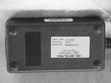
Click to zoom
Application Details
- Equipment Class
- DSS - Part 15 Spread Spectrum Transmitter
- Date of Grant
- Oct 16, 2001
- Application Purpose
- Original Equipment
- Date of Application
- Jul 09, 2001
- Frequency Range
- 2412.00000000 - 2462.00000000
- Company
- Amplidyne Inc.
- Country
- United States
Documents & Files
Document Text
Text extracted from the exhibit documents filed with the FCC. Open a document above to read the original.
Users Manual
AmpWave TM 11Mbps Central Site Installation Figure 4 shows a block schematic of the installation procedure for the Central Site Ampwave TM Installation. Your Kit should include the following equipment: A. AMP 1124BTS – Base Station (1) is provided with a 120vac to 12V D.C. to D.C. converter ADC-12AP-120 (2). The BTS is mounted into standard 19” Rack using the BTS mounting sockets on the front of the unit (3). Connect the RJ45 ethernet cable (4) to the Ethernet socket at the back of the AMP11240BTS (Access Point) and the other end to your hub via the cross over cable. Connect the DC/DC converter to a 120vac socket and the other to the AMP1124BTS after the test of the installation is complete. B. 2-foot length of Stress Relief Cable (5) is connected to the reverse SMA connector of the AMP11240BTS. This stress relief provides stress relief between the large LMR400 Cables with N Connectors. In between the stress relief cable and the 100’ large LMR400 cable the DC Injector (7) is connected. The DC Injector is directional and is clearly marked as to the orientation for mounting the unit. An N type, male to male adapter (6) is required to be connected between the stress relief cable and the D.C. Injector. C. The D.C. Injector is used to supply +12V to the tower top Amplifier, AMP2425-27S. A 120vac to 12v converter ADC-12-AMP-120 (8) is supplied with the kit. Connect the line cord (9) of the converter to a 120vac socket. Connect the other end to the D.C. Injector after the installation is complete. D. LMR400 – this cable (10) is supplied with the kit and has two N-type male connectors at each end. E. The Bi-directional Amplifier, AMP2425-27 (11) is supplied with the kit and has 2 mounting brackets which connect the amplifier to the Mast – See Figure 2 for the installation directions of the Amplifier in detail. The Amplifier is directional and is clearly marked as to the orientation for mounting the unit. F. A short 6” length of LMR400 cable (12) is used to connect to the Lightening Arrester (13). The lightening Arrester must be suitable grounded. G. Finally the 10 dBi Omni Antenna (15), or optional antennas is connected to the lightning arrestor with a N- type male to male adapter cable (14) which is provided with the kit. The optional antennas are: a. AOM5 b. AOM8 Page 1 c. INET-OMNI-10 d. INET-ANT-15 e. APN-7 The mounting instructions for the 10 dBi OMNI, AOM10 are detailed as illustrated in Section B. Mounting Instructions for the remainder of the AMPDNET TM antennas are provided with the antennas. Page 2 Figure 4 Page 3 The Central Site Kit 1. AMP11240BTS – Base Station 2. ADC-12AP-120 – 120vac to 12v D.C. to D.C. Converter 3. Mounting Sockets 4. RJ45 Ethernet Cable 5. Stress Relief Cable 6. N- type Male-to-Male Adapter 7. DC Injector 8. ADC-12AMP-120 - 120vac Converter 9. Line Cord 10. LMR400 11. AMP2425-27S 12. LMR400 Cable 13. Lightning Arrestor 14. N-type Male-to-Male Adapter Cable 15. Antenna The FCC warning relate to all Antennas used. Please refer to instructions in your kit. WARNING: The AMPDNET TM Antenna should be installed only by an experienced antenna installer familiar with local building and safety codes and, wherever necessary, licensed by appropriate government regulatory bodies. Failure not to do so, may void the Product Warrantee, as well as expose the end user to legal and financial liabilities. Amplidyne, Inc., it’s agents, resellers, or distributors, are not liable of injury, damage or violation of government regulations associated with the installation of the antenna. The installer is responsible for ensuring that the public is not exposed to radio energy levels in excess of the FCC guidelines. Those guidelines imply that no human may conceivably be found within one foot of the front of the antenna. If such a situation is likely to occur, the installer is responsible for placing the appropriate caution signs to warn the public. Amplidyne, Inc., it’s agents, resellers, or distributors are not liable for exposure to excessive RF energy levels due to improper antenna installation. The Maximum Permissible Exposure guidelines are 1 foot (30cm) for the AMPDNET TM unit, as based on the National Council on Radiation Protection and Measurement (NCRP). If the antenna is in an accessible area, an appropriate warning sign must be installed in the appropriate place by the installer. WARNING: Using an antenna or cable other than those supplied or recommended for use with the AMPDNET TM units, whether installer indoors or outdoors, could cause degradation of the system and could void your authority to operate this equipment. In addition, the use of unauthorized antennas or external amplifiers violates Federal Law and FCC’s regulations. This may void the Product Warranty, as well as expose the end user to legal and financial liabilities. WARNING: The AMPDNET TM Antenna emits high radio frequency energy levels. In order to comply with FCC RF Exposure requirements the antenna must be installed in a manner that will provide a minimum separation distance of 1 foot, (30 cm) between the antenna and all persons. Page 4 Example of Omni Directional The Omni directional antenna available for use with the AMPDNET TM Central Site equipment is intended for external mounting and should be used when full 360-degree coverage is desired. When this antenna is mounted on a mast, it must be located as high as possible in order to avoid any other object located beside it. The OMNI antenna has a very narrow vertical beam width. Both the height and distance separation between the 2 sites must be taken into consideration when selecting the antenna in order to maximize the coverage area. Following are the steps required to install the antenna for the AMPDNET TM System. To install the Omni Antenna: 1. Mount the antenna using the enclosed brackets, following the instructions included with the antenna and cable kit that you purchased. WARNING: AMPDNET TM Antenna should be installed only by experienced antenna in…
Text truncated - open the document above for the full version.
Parts List/Tune Up Info
INET-ANT-15 15 dBi Directional Parabolic Grid 22dBm APN-7 7 dBi Directional 22dBm AOM-10 10 dBi Vertically polarized Omni directional 22dBm AOM-8 8 dBi Vertically polarized Omni directional 22dBm AOM-5 5 dBi Vertically polarized Omni directional 22dBm
Test Report
Test Report Number R-8903-2 APPLICANT Amplidyne Inc. 59 LaGrauge Street Raritan, NJ 08869 MANUFACTURER Amplidyne Inc. 59 LaGrauge Street Raritan, NJ 08869 TEST SPECIFICATION:FCC Rules and Regulations Part 15, Subpart C TEST PROCEDURE:ANSI C63.4:1992 TEST SAMP LE DESCRIP TION BRANDNAME:Amplidyne Inc. MODEL:CENTRAL SITE FCC ID:OZMAMP11240BTS TYPE:2.4 GHz Direct Sequence Spread Spectrum Transmitter System FREQUENCY RANGE:2400 MHz TO 2483.5 MHz POWER REQUIREMENTS: 12 VDC derived from DC Injection TESTS P ERFORMED - 15.207(a)Conducted Emissions, AC Power - 15.209(a)Spurious Case Radiated Emissions, Restricted Bands - 15.247(a)(2)Occupied Bandwidth - 15.247(b)(1)Power Output - 15.247(c)Spurious Emissions, Antenna Conducted Emissions - 15.247(d)Power Density - 15.247(e)Processing Gain Data Test Report Number R-8903-2 REPORT OF MEASUREMENTS Applicant:Amplidyne Inc. Device:2.4 GHz Direct Sequence Spread Spectrum Transmitter System FCC ID:OZMAMP11240BTS Power Requirements:12 VDC derived from DC Injection Applicable Rule Section:Part 15, Subpart C, Section 15.247 TEST RESULTS 15.207(a):The radio frequency voltage that was conducted back on to the AC power line on any frequency/frequencies within the bandwidth of 450kHz to 30MHz did not exceed 250 microvolts. 15.247(a)(2): The minimum 6dB bandwidth was no less than 500 kHz. 15.247(b)(1): The maximum peak output power of the transmitter did not exceed 1 watt. The test samples peak power measured 213.8 mW(23.3 dBm) at the antenna terminals. 15.247(b)(3) The system utilizes antennas which have directional gain greater than 6 dBi. The device operates in the 2400 to 2483.5 MHz band and is used exclusively for fixed point to point operations. The maximum gain antenna used with this system has a gain of 16 dBi. Therefore the output power was reduced 1 dB for every 3 dB above a gain of 6dBi yielding a maximum allowable output power at the antenna terminal of 26.7 dBm= 464 mW. 15.247(b)(4) The device does not operate in such a manner that causes the public to be exposed to levels in excess of the commissions guidelines. The device is used for fixed point to point operations where the transmit antenna is located on a mast external to a building well away from public exposure. In addition the installation guide states that the installer should keep the antenna at least 1 foot from possible human exposure and if this is not possible, appropriate warning signs shall be posted. 15.247(c):The antenna conducted emissions were found to be at least 20dB down from the fundamental frequencies. All other emissions within the restricted bands specified in 15.205 did not exceed the general radiated emissions limits specified in 15.209(a). 15.247(d):The power density did not exceed 8dBm in any 3 kHz bandwidth averaged over 1 second. 15.247(e)The process gain information was supplied by Amplidyne Inc. and can be found as a separate e-file attachment named Processing Gain.pdf. Test Report Number R-8903-2 GENERAL NOTES 1.All readings were taken using a peak detector function at a distance of 3 meters. 2. The duty cycle was applied to the peak readings in order to determine the average value of emissions. 3.The device operates from 2400 MHz TO 2483.5 MHz. Therefore, where applicable, measurements were taken at three center frequencies; low, middle and high (2422 MHz, 2447 MHz and 2462 MHz). 4. The frequency range was scanned form 30 MHz to 25 GHz. All emissions not reported were more than 10dB below the specified limit. 5.Spurious Radiated Emissions located in the restricted bands listed in Paragraph 15.205 were measured with each of the following antennas attached to the system: 1). AOM - 5 2). AOM - 8 3). INET-OMNI-10 4). INET-ANT-15 5). Flat “wall mount” APN - 7 6.The device is a spread spectrum transmission system consisting of a spread spectrum transmitter (FCC ID: M4Y-WL2450), a DC Injector, a lightning arrestor, an RF amplifier, and the five antennas listed above. In accordance with Paragraph 15.204, this device is being marketed as a system and will only be used in this configuration. Test Report Number R-8903-2 EXHIBIT 4 Conducted Emissions Para. 15.207(a) (Please see separate e-file attachments named CEdata.pdf) Test Report Number R-8903-2 EXHIBIT 4 Occupied Bandwidth Para. 15.247(a)(2) (Please see separate e-file attachments named OccBw.pdf) Test Report Number R-8903-2 EXHIBIT 4 Power Output Para. 15.247(b) (Please see separate e-file attachments named pwrout.pdf) Test Report Number R-8903-2 EXHIBIT 4 Antenna Conducted Emissions Para. 15.247(c) (Please see separate e-file attachments named antce2.462 GHz, 1-7.pdf, antce2.462 GHz, 8-14.pdf antce2.412 GHz, 1-7.pdf, antce2.412 GHz, 8-14.pdf, antce2.437 GHz, 1-7.pdf, antce2.437 GHz, 8-14.pdf) Test Report Number R-8903-2 EXHIBIT 4 Spurious Case Radiated Emissions, Restricted Bands Para. 15.209(a) (Please see separate e-file attachments named Radiated Emissions.pdf) Test Report Number R-8903-2 EXHIBIT 4 Power Density Para. 15.247(d) (Please see separate e-file attachments named pwrden.pdf) Test Report Number R-8903-2 EXHIBIT 4 Processing Gain Data Para. 15.247(e) (Please see separate e-file attachments named ProcessGain1.pdf, ProcessGain2.pdf, ProcessGain3.pdf) Test Report Number R-8903-2 EQUIPMENT LISTS Radiated Emissions Fundamental and Harmonics, 30MHz-25GHz ENTypeManufacture rDe scriptionMode l No.Cal Date Due Date 032GH.P. FilterMicrolab/FXR3 GHz - 6 GHzHA-30N05/02/200005/02/2001 067Open Area Test SiteRetlif3 MeterRNY09/20/200009/20/2003 128CDouble Ridge GuideEaton Corporation1 GHz - 18 GHz9600109/18/200009/18/2001 133Broadband Pre-AmplifierElectro-Metrics10 kHz - 1 GHz, 26dBBPA-100006/13/200006/13/2001 141Spectrum AnalyzerHewlett Packard100 Hz - 40 GHz8566B02/20/200108/20/2001 141AGraphics PlotterHewlett PackardN/A7470A03/05/200103/05/2002 141BQuasi-Peak AdaptorHewlett Packard100 Hz - 1 GHz85650A02/20/200108/20/2001 333AttenuatorNardaDC - 11 GHz768-1006/26/200006/26/2001 523BiconilogElectro-Mechanics26 - 2000 MHz314…
Text truncated - open the document above for the full version.
Test Report
TABULAR DATA SHEET CUSTOMER: MODEL No.: TEST SAMPLE: SERIAL No.: TEST SPECIFICATION: TEST METHOD: OPERATING MODE: TECHNICIAN:DATE: RETLIF TESTING LABORATORIES NOTES: DATA SHEETOF JOB No.: PARAGRAPH: Limit based on highest antenna gain of 16 dBi 2.4 GHz Direct Sequence Spread Spectrum Transmitter R-8903-2 The peak output power at the antenna terminals of the EUT was measured utilizing a peak power meter. The transmitter complies wth the FCC power output requirements of 15.247(c)(3)(i). 26.7 26.7 26.7 18.9 22.0 20.9 2412 2437 2462 1 6 11 dBmdBmMHz LimitOutput PowerFrequencyChannel Continuously transmitting at the frequency specified below. 15.247(b)(3)(i) FCC Part 15 T. Schneider TransmitterPeak Output Power R-8903-2Amplidyne Central SiteN/A 11
Test Report
Retlif Testing Laboratories R Retlif Job Number R-8903-2 Data Sheet 1 of 1 Test Method: FCC Part 15 Subpart C, Restricted Band Radiated Emissions, Paragraph 15.247(c) Customer: Amplidyne Inc. Job No. R-8903-2 Test Sample: 2.4GHz Direct Sequence Spread Spectrum Transmitter/ Parabolic Antenna Model No.: Central Site/INET-ANT-15 Serial No. N/A . Operating Mode: Continuously transmitting a signal at 2.412GHz CH1, through a 15dBi Parabolic antenna. Technician: Peter Lananna Date: April 3, 2001 Notes: Test Distance: 3 Meters Temp:18C Humidity:34% Duty cycle correction, from Peak Detector: Quasi-Peak Below 30 MHz to 1 GHz, Peak above 1 GHz to Average=-44.4dB Test Freq. Antenna Position EUT Orientation Meter Readings Correction Factor Corrected Reading Converted Reading Peak/Avg Limit MHz (V/H) / Meters Degrees dBuV dB dBuV/m uV/m uV/m 30.00 100 | | 88.00 100 88.00 150 l | 216.00 150 216.00 200 | | 960.00 200 960.00 500 | | 2390.0 H/1.0 180 63.1 2.8 65.9/21.5 1972.4/11.9 5000/500 | | | 2483.5 H/1.0 180 55.3 3.6 58.9/14.5 881.0/5.3 5000/500 | | | 4826.0 V/1.0 180 31.0 12.5 43.5 149.6* | | | | | | | | | | | | | | | | | | | | | | | | | | | l | 25000.0 5000/500 | The EUT was scanned from 30 MHz to 25 GHz The emissions observed from the EUT do not exceed the specified limits. Emissions not recorded were more than 10dB under the specified limit *= Denotes minimum system sensitivity. Retlif Testing Laboratories R Retlif Job Number R-8903-2 Data Sheet 2 of 2 Test Method: FCC Part 15 Subpart C, Restricted Band Radiated Emissions, Paragraph 15.247(c) Customer: Amplidyne Inc. Job No. R-8903-2 Test Sample: 2.4GHz Direct Sequence Spread Spectrum Transmitter/ Parabolic Antenna Model No.: Central Site/INET-ANT-15 Serial No. N/A . Operating Mode: Continuously transmitting a signal at 2.437GHz CH6, through a 15dBi Parabolic antenna. Technician: Peter Lananna Date: April 3, 2001 Notes: Test Distance: 3 Meters Temp:18C Humidity:34% Duty cycle correction, from Peak Detector: Quasi-Peak Below 30 MHz to 1 GHz, Peak above 1 GHz to Average=-44.4dB Test Freq. Antenna Position EUT Orientation Meter Readings Correction Factor Corrected Reading Converted Reading LIMIT MHz (V/H) / Meters Degrees dBuV dB dBuV/m uV/m uV/m 30.00 100 | | 88.00 100 88.00 150 l | 216.00 150 216.00 200 | | 960.00 200 960.00 500 | | 2390.0 H/1.0 180 52.8 2.8 55.6/11.2 602.6/3.6 5000/500 | | 2483.5 H/1.0 180 56.5 3.6 60.1/15.7 1011.6/6.1 5000/500 | | | | | | | | | | | | | | | | | | | | | | | | | | | | | | l | 25000.0 5000/500 The EUT was scanned from 30 MHz to 25 GHz The emissions observed from the EUT do not exceed the specified limits. Emissions not recorded were more than 10dB under the specified limit *= Denotes minimum system sensitivity. Retlif Testing Laboratories R Retlif Job Number R-8903-2 Data Sheet 3 of 3 Test Method: FCC Part 15 Subpart C, Restricted Band Radiated Emissions, Paragraph 15.247(c) Customer: Amplidyne Inc. Job No. R-8903-2 Test Sample: 2.4GHz Direct Sequence Spread Spectrum Transmitter/ Parabolic Antenna Model No.: Central Site/INET-ANT-15 Serial No. N/A . Operating Mode: Continuously transmitting a signal at 2.462GHz CH11, through a 15dBi Parabolic antenna. Technician: Peter Lananna Date: April 3, 2001 Notes: Test Distance: 3 Meters Temp:18C Humidity:34% Duty cycle correction, from Peak Detector: Quasi-Peak Below 30 MHz to 1 GHz, Peak above 1 GHz to Average=-44.4dB Test Freq. Antenna Position EUT Orientation Meter Readings Correction Factor Corrected Reading Converted Reading Peak/Avg Limit MHz (V/H) / Meters Degrees dBuV dB dBuV/m uV/m uV/m 30.00 100 | | 88.00 100 88.00 150 l | 216.00 150 216.00 200 | | 960.00 200 960.00 500 | | | | | 2390.0 V/1.0 180 46.5 2.8 49.3 291.7* | | | 2483.5 H/1.0 180 64.7 3.6 68.3/23.9 2600.1/15.7 5000/500 | | | | | | | | | | | | | | | | | | | | | | | | | | l | 25000.0 5000/500 The EUT was scanned from 30 MHz to 25 GHz The emissions observed from the EUT do not exceed the specified limits. Emissions not recorded were more than 10dB under the specified limit *= Denotes minimum system sensitivity. Retlif Testing Laboratories R Retlif Job Number R-8903-2 Data Sheet 4 of 4 Test Method: FCC Part 15 Subpart C, Restricted Band Radiated Emissions, Paragraph 15.247(c) Customer: Amplidyne Inc. Job No. R-8903-2 Test Sample: 2.4GHz Direct Sequence Spread Spectrum Transmitter/ Omni-directional Antenna Model No.: Central Site/INET-OMNI-10 Serial No. N/A . Operating Mode: Continuously transmitting a signal at 2.412GHz CH1, with a 10dBi Omni-directional antenna. Technician: Peter Lananna Date: April 3, 2001 Notes: Test Distance: 3 Meters Temp:18C Humidity:34% Duty cycle correction, from Peak Detector: Quasi-Peak Below 30 MHz to 1 GHz, Peak above 1 GHz to Average=-44.4dB Test Freq. Antenna Position EUT Orientation Meter Readings Correction Factor Corrected Reading Converted Reading Peak/Avg Limit MHz (V/H) / Meters Degrees dBuV dB dBuV/m uV/m uV/m 30.00 100 | | 88.00 100 88.00 150 l | 216.00 150 216.00 200 | | 960.00 200 960.00 500 | | 2390.0 H/1.8 180 60.0 2.8 62.8/18.4 1288.2/8.3 5000/500 | | 2483.5 V/1.0 180 46.2 3.6 49.8 309.0* | | | 4826.0 V/1.0 180 31.0 12.5 43.5 149.6* | | | | | | | | | | | | | | | | | | | | | | | | | | | l | 25000.0 5000/500 500 The EUT was scanned from 30 MHz to 25 GHz The emissions observed from the EUT do not exceed the specified limits. Emissions not recorded were more than 10dB under the specified limit * =Denotes minimum system sensitivity. Retlif Testing Laboratories R Retlif Job Number R-8903-2 Data Sheet 5 of 5 Test Method: FCC Part 15 Subpart C, Restricted Band Radiated Emissions, Paragraph 15.247(c) Customer: Amplidyne Inc. Job No. R-8903-2 Test Sample: 2.4GHz Direct Sequence Spread Spectrum Transmitter/ Omni-directional Antenna Model No.: Central Site/INET-OMNI-10 Serial No. N/A . Operating Mode: Continuously transmitting a signal at 2.437GHz CH6, with a 10dBi Omni-directional antenna. Technician: Peter Lananna Date: April 3, 2001 Notes: Test Distance: 3 Meters Temp:18C Humi…
Text truncated - open the document above for the full version.
Contact Information
Applicant
Devendar S Bains(Engineering Director)
Technical Contact
Retlif Testing LaboratoriesThomas J Schneider
[email protected]631-737-1500
795 Marconi Avenue · Ronkonkoma, New York · United States
Non-Technical Contact
Retlif Testing LaboratoriesMichelle White
[email protected]631-737-1500
Test Firm
Retlif Testing LaboratoriesMichael Bozza
Technical Specifications
| # | Rule Parts | Frequency Range | Power Output |
|---|---|---|---|
| 1 | 15C | 2.41 GHz - 2.46 GHz | 160.00 mW |
Other Applications from Amplidyne Inc.
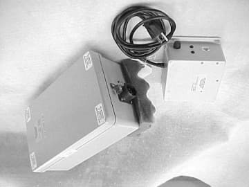
OZMMCELL2411A
Oct 08, 2001DSS - Part 15 Spread Spectrum Transmitter
Equipment Class
DSS - Part 15 Spread Spectrum Transmitter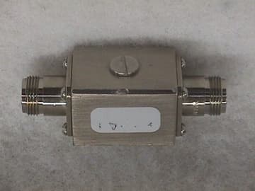
OZMAMP2425-27S
Aug 07, 2000AmpDNet System
Equipment Class
DSS - Part 15 Spread Spectrum Transmitter