OZMAMP2425-27SAmpDNet System
Amplidyne Inc.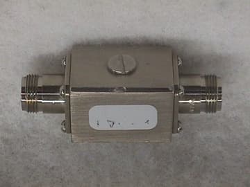
Click to zoom
Application Details
- Equipment Class
- DSS - Part 15 Spread Spectrum Transmitter
- Date of Grant
- Aug 07, 2000
- Application Purpose
- Original Equipment
- Date of Application
- May 03, 2000
- Equipment Note
- AmpDNet System
- Frequency Range
- 2412.00000000 - 2462.00000000
- Company
- Amplidyne Inc.
- Country
- United States
Documents & Files
Document Text
Text extracted from the exhibit documents filed with the FCC. Open a document above to read the original.
RF Exposure Info
RF Exposure Information: 15.247(b)(4) The device does not operate in such a manner that causes the public to be exposed to levels in excess of the commissions guidelines. The device is used for fixed point to point operations where the transmit antenna is located on a mast external to a building well away from public exposure. In addition the installation guide states that the installer should keep the antenna at least 1 foot from possible human exposure and if this is not possible, appropriate warning signs shall be posted. The maximum output power measured at the antenna terminal of the device was 23.3 dBm( See test report for measurements). The device utilizes a parabolic grid antenna with a maximum gain of 19 dBi. The antenna characteristics are listed in the users manual exhibit. Please note that although there is a parabolic grid antenna with a gain of 24 dBi, it did not qualify with this system.
Test Report
Test Report Number R-8392-1 APPLICANT Amplidyne Inc. 59 LaGrauge Street Raritan, NJ 08869 MANUFACTURER Amplidyne Inc. 59 LaGrauge Street Raritan, NJ 08869 TEST SPECIFICATION:FCC Rules and Regulations Part 15, Subpart C TEST PROCEDURE:ANSI C63.4:1992 TEST SAMP LE DESCRIP TION BRANDNAME:Amplidyne Inc. MODEL:AMP-2425-27S FCC ID:XXXAMP2425-27S TYPE:2.4 GHz Direct Sequence Spread Spectrum Transmitter System FREQUENCY RANGE:2412 to 2462 MHz POWER REQUIREMENTS: 12 VDC derived from an AC Adapter Model : MW41-1200500 TESTS P ERFORMED - 15.207(a)Conducted Emissions, AC Power - 15.209(a)Spurious Case Radiated Emissions, Restricted Bands - 15.247(a)(2)Occupied Bandwidth - 15.247(b)(1)Power Output - 15.247(c)Spurious Emissions, Antenna Conducted Emissions - 15.247(d)Power Density - 15.247(e)Processing Gain Data Test Report Number R-8392-1 REPORT OF MEASUREMENTS Applicant:Amplidyne Inc. Device:2.4 GHz Direct Sequence Spread Spectrum Transmitter System FCC ID:XXXAMP2425-27S Power Requirements:12 VDC derived from an AC Adapter Model : MW41-1200500 Applicable Rule Section:Part 15, Subpart C, Section 15.247 TEST RESULTS 15.207(a):The radio frequency voltage that was conducted back on to the AC power line on any frequency/frequencies within the bandwidth of 450kHz to 30MHz did not exceed 250 microvolts. 15.247(a)(2): The minimum 6dB bandwidth was no less than 500 kHz. 15.247(b)(1): The maximum peak output power of the transmitter did not exceed 1 watt. The test samples peak power measured 213.8 mW(23.3 dBm) at the antenna terminals. 15.247(b)(3) The system utilizes antennas which have directional gain greater than 6 dBi. The device operates in the 2400 to 2483.5 MHz band and is used exclusively for fixed point to point operations. The maximum gain antenna used with this system has a gain of 19 dBi. Therefore the output power was reduced 1 dB for every 3 dB above a gain of 6dBi yielding a maximum allowable output power at the antenna terminal of 25.7 dBm= 369 mW. 15.247(b)(4) The device does not operate in such a manner that causes the public to be exposed to levels in excess of the commissions guidelines. The device is used for fixed point to point operations where the transmit antenna is located on a mast external to a building well away from public exposure. In addition the installation guide states that the installer should keep the antenna at least 1 foot from possible human exposure and if this is not possible, appropriate warning signs shall be posted. 15.247(c):The antenna conducted emissions were found to be at least 20dB down from the fundamental frequencies. All other emissions within the restricted bands specified in 15.205 did not exceed the general radiated emissions limits specified in 15.209(a). 15.247(d):The power density did not exceed 8dBm in any 3 kHz bandwidth averaged over 1 second. 15.247(e)The process gain information was supplied by Amplidyne Inc. and can be found as Test Report Number R-8392-1 a separate e-file attachment named Processing Gain.pdf. GENERAL NOTES 1.All readings were taken using a peak detector function at a distance of 3 meters. 2. The duty cycle was applied to the peak readings in order to determine the average value of emissions. 3.The device operates from 2412 MHz to 2462 MHz. Therefore, where applicable, measurements were taken at three center frequencies; low, middle and high (2422 MHz, 2447 MHz and 2462 MHz). 4. The frequency range was scanned form 30 MHz to 25 GHz. All emissions not reported were more than 10dB below the specified limit. 5.Spurious Radiated Emissions located in the restricted bands listed in Paragraph 15.205 were measured with each of the following antennas attached to the system: A). Omni Directional Antenna, Model No.: OMNI-INET-10, Maximum gain=10 dBi B). Flat Panel Antenna, Model No.: APN-13, Maximum gain=13dBi C). Flat Panel Antenna, Model No.:INET-PNL-16, Maximum gain=16 dBi D). Parabolic Grid Antenna, Model No.: INET-ANT-15, Maximum gain=15 dBi E). Parabolic Grid Antenna, Model No.: APG-15, Maximum gain=15 dBi F). Parabolic Grid Antenna, Model No.: INET-ANT-19, Maximum gain=19 dBi NOTE: Although a Parabolic Grid Antenna with 24 dBi gain is shown in the users manual, it did not qualify to be used with this system. 6. The device is a spread spectrum transmission system consisting of a spread spectrum transmitter(FCC ID: M4Y-WL2450), a DC Injector, a lightning arrestor, an RF amplifier, and the six antennas listed above. In accordance with Paragraph 15.204, this device is being marketed as a system and will only be used in this configuration. Test Report Number R-8392-1 EXHIBIT 4 Conducted Emissions Para. 15.207(a) (Please see separate e-file attachments named CEdata.pdf) Test Report Number R-8392-1 EXHIBIT 4 Occupied Bandwidth Para. 15.247(a)(2) (Please see separate e-file attachments named OccBw.pdf) Test Report Number R-8392-1 EXHIBIT 4 Power Output Para. 15.247(b) (Please see separate e-file attachments named pwroutput.pdf) Test Report Number R-8392-1 EXHIBIT 4 Antenna Conducted Emissions Para. 15.247(c) (Please see separate e-file attachments named Antce1-6.pdf, Antce7-12.pdf, Antce13-18.pdf, Antce19-24.pdf, Antce25-30.pdf, Antce31-34.pdf) Test Report Number R-8392-1 EXHIBIT 4 Spurious Case Radiated Emissions, Restricted Bands Para. 15.209(a) (Please see separate e-file attachments named Spurious RE.pdf) Test Report Number R-8392-1 EXHIBIT 4 Power Density Para. 15.247(d) (Please see separate e-file attachments named pwrden.pdf) Test Report Number R-8392-1 EXHIBIT 4 Processing Gain Data Para. 15.247(e) (Please see separate e-file attachments named Processing Gain.pdf) Test Report Number R-8392-1 EQUIPMENT LISTS Occupied Bandwidth ENTypeManufacture rFre que ncy RangeMode l No.Cal DateDue Date 141Spectrum AnalyzerHewlett Packard100 Hz - 40 GHz8566B03/20/2000 09/20/2000 141A Graphics PlotterHewlett PackardN/A7470A03/08/2000 03/08/2001 141B Quasi-Peak AdaptorHewlett Packard100 Hz - 1 GHz85650A03/20/2000 09/20/2000 332AttenuatorNardaDC - 1…
Text truncated - open the document above for the full version.
Test Report
Retlif Testing Laboratories R Retlif Job Number R-8288 Data Sheet 1 of 6 Test Method: FCC Part 15 Subpart C, Spurious Case Radiated Emissions, Paragraph 15.209(a) Customer: Amplidyne, Inc. Job No. R-8288 Test Sample: 2.4GHz Spread Spectrum Amp. with 9dB gain Omni Antenna. Antenna No.: INET-OMNI-10 FCC ID: XXX AMP2425-27S Operating Mode: Continuous Tx of 2.4GHz Spread Spectrum Signal. Technician: P. Lananna Date: April 27, 2000 Notes: Test Distance: 3 Meters Temp:9C Humidity:37% Duty Cycle=0.5% Detector: Quasi-Peak Below 1 GHz, Peak above 1 GHz D.C.Correction=-46.0dB Test Freq. Antenna Position EUT Orientation Meter Readings Correction Factor Corrected Reading Converted Reading LIMIT MHz (V/H) / Meters Degrees dBuV dB dBuV/m uV/m uV/m 30.00 100 | | 88.00 100 88.00 150 | | 216.00 150 216.00 200 | | 960.00 200 960.00 5000/500 | Peak/avg | CH.3 | 2386 V/1.0 180 72.7 -6.1 66.6 2138.0/1.07 | 2500 V/1.0 180 63.1 -3.2 59.9 988.6/0.49 | l | CH.6 | 2390 V/1.0 180 38.1 -7.6 30.5 33.5/0.02* | 2500 V/1.0 180 38.1 -7.6 30.5 33.5/0.02* | | | CH.11 | 2390 V/1.0 180 39.2 23 62.2 1288.2/0.64 | 2484 V/1.0 180 43.6 23 66.6 2138.0/1.07 | | | | | | | | | | | | | | | | | 25000.0 5000/500 Peak/avg The EUT was scanned from 30 MHz to 25 GHz The emissions observed from the EUT do not exceed the specified limits. Emissions not recorded were more than 10dB under the specified limit. *=Noise Floor Measurements (Minimum system) )sensitivity Retlif Testing Laboratories R Retlif Job Number R-8288 Data Sheet 2 of 6 Test Method: FCC Part 15 Subpart C, Spurious Case Radiated Emissions, Paragraph 15.209(a) Customer: Amplidyne, Inc. Job No. R-8288 Test Sample: 2.4GHz Spread Spectrum Amp. with 13dB gain Panel Antenna. Antenna No.: APN13 FCC ID: XXXAMP2425-27S Operating Mode: Continuous Tx of 2.4GHz Spread Spectrum Signal. Technician: P. Lananna Date: April 27, 2000 Notes: Test Distance: 3 Meters Temp:9C Humidity:37% Duty Cycle=0.5% Detector: Quasi-Peak Below 1 GHz, Peak above 1 GHz D.C.Correction=-46.0dB Test Freq. Antenna Position EUT Orientation Meter Readings Correction Factor Corrected Reading Converted Reading LIMIT MHz (V/H) / Meters Degrees dBuV dB dBuV/m uV/m uV/m 30.00 100 | | 88.00 100 88.00 150 | | 216.00 150 216.00 200 | | 960.00 200 960.00 5000/500 | Peak/avg | CH.3 | 2390 V/1.0 180 45.2 23 68.2 2570.4/1.28 | 2489 V/1.0 180 39.8 23 62.8 1380.4/0.69 | l | CH.6 | 2390 V/1.0 180 38.3 -7.6 30.7 34.3/0.02* | 2500 V/1.0 180 38.3 -7.6 30.7 34.3/0.02* | | | CH.11 | 2390 V/1.0 180 44.7 23 67.7 2398.8/1.20 | 2486 V/1.0 180 50.3 23 73.3 4623.8/2.31 | | | | | | | | | | | | | | | | | 25000.0 5000/500 Peak/avg The EUT was scanned from 30 MHz to 25 GHz The emissions observed from the EUT do not exceed the specified limits. Emissions not recorded were more than 10dB under the specified limit. *=Noise Floor Measurements (Minimum system) )sensitivity Retlif Testing Laboratories R Retlif Job Number R-8288 Data Sheet 3 of 6 Test Method: FCC Part 15 Subpart C, Spurious Case Radiated Emissions, Paragraph 15.209(a) Customer: Amplidyne, Inc. Job No. R-8288 Test Sample: 2.4GHz Spread Spectrum Amp. with 15dB gain Parabolic Antenna. Antenna No.: INET-ANT-15 FCC ID: XXXAMP2425-27S Operating Mode: Continuous Tx of 2.4GHz Spread Spectrum Signal. Technician: P. Lananna Date: April 27, 2000 Notes: Test Distance: 3 Meters Temp:9C Humidity:37% Duty Cycle=0.5% Detector: Quasi-Peak Below 1 GHz, Peak above 1 GHz D.C.Correction=-46.0dB Test Freq. Antenna Position EUT Orientation Meter Readings Correction Factor Corrected Reading Converted Reading LIMIT MHz (V/H) / Meters Degrees dBuV dB dBuV/m uV/m uV/m 30.00 100 | | 88.00 100 88.00 150 | | 216.00 150 216.00 200 | | 960.00 200 960.00 5000/500 | Peak/avg | CH.3 | 2390 V/1.0 180 44.8 23 67.8 2454.7/1.23 | 2484 V/1.0 180 42.0 23 65.0 1778.3/0.89 | l | CH.6 | 2390 V/1.0 180 37.8 -7.6 30.2 32.4/0.02* | 2500 V/1.0 180 37.8 -7.6 30.2 32.4/0.02* | | | CH.11 | 2390 V/1.0 180 43.3 23 66.3 2065.4/1.03 | 2487 V/1.0 180 50.4 23 73.4 4677.4/2.34 | | | | | | | | | | | | | | | | | 25000.0 5000/500 Peak/avg The EUT was scanned from 30 MHz to 25 GHz The emissions observed from the EUT do not exceed the specified limits. Emissions not recorded were more than 10dB under the specified limit. *=Noise Floor Measurements (Minimum system) )sensitivity Retlif Testing Laboratories R Retlif Job Number R-8288 Data Sheet 4 of 6 Test Method: FCC Part 15 Subpart C, Spurious Case Radiated Emissions, Paragraph 15.209(a) Customer: Amplidyne, Inc. Job No. R-8288 Test Sample: 2.4GHz Spread Spectrum Amp. with 15dB gain Parabolic Antenna. Antenna No.: APG15 FCC ID: XXXAMP2425-27S Operating Mode: Continuous Tx of 2.4GHz Spread Spectrum Signal. Technician: P. Lananna Date: April 27, 2000 Notes: Test Distance: 3 Meters Temp:9C Humidity:37% Duty Cycle=0.5% Detector: Quasi-Peak Below 1 GHz, Peak above 1 GHz D.C.Correction=-46.0dB Test Freq. Antenna Position EUT Orientation Meter Readings Correction Factor Corrected Reading Converted Reading LIMIT MHz (V/H) / Meters Degrees dBuV dB dBuV/m uV/m uV/m 30.00 100 | | 88.00 100 88.00 150 | | 216.00 150 216.00 200 | | 960.00 200 960.00 5000/500 | Peak/avg | CH.3 | 2390 V/1.0 180 49.8 23 72.8 4365.2/2.18 | 2495 V/1.0 180 43.3 23 66.3 2065.4/1.03 | l | CH.6 | 2390 V/1.0 180 35.6 -7.6 28.0 25.1/0.01* | 2500 V/1.0 180 35.6 -7.6 28.0 25.1/0.01* | | | CH.11 | 2390 V/1.0 180 46.9 23 69.9 3126.1/1.56 | 2487 V/1.0 180 50.2 23 73.2 4570.9/2.29 | | | | | | | | | | | | | | | | | 25000.0 5000/500 Peak/avg The EUT was scanned from 30 MHz to 25 GHz The emissions observed from the EUT do not exceed the specified limits. Emissions not recorded were more than 10dB under the specified limit. *=Noise Floor Measurements (Minimum system) )sensitivity Retlif Testing Laboratories R Retlif Job Number R-8288 Data Sheet 5 of 6 Test Method: FCC Part 15 Subpart C, Spurious Case Radiated Emissions, Paragraph 15.209(a) Customer: Amplidyne, Inc. Job No. R-8288 Test Sample: 2.4GHz Spread Spectrum Amp. with 16dB gain Panel Antenna. An…
Text truncated - open the document above for the full version.
Contact Information
Applicant
Devendar S Bains(Engineering Director)
Technical Contact
Retlif Testing LaboratoriesThomas J Schneider
[email protected]631-737-1500
795 Marconi Avenue · Ronkonkoma, New York · United States
Non-Technical Contact
Retlif Testing LaboratoriesMichelle Tirado
[email protected]631-737-1500
Technical Specifications
| # | Rule Parts | Frequency Range | Power Output |
|---|---|---|---|
| 1 | 15.247 | 2.41 GHz - 2.46 GHz | 269.00 mW |
Other Applications from Amplidyne Inc.
OZMAMP11240BTS
Oct 16, 2001DSS - Part 15 Spread Spectrum Transmitter
Equipment Class
DSS - Part 15 Spread Spectrum Transmitter
OZMMCELL2411A
Oct 08, 2001DSS - Part 15 Spread Spectrum Transmitter
Equipment Class
DSS - Part 15 Spread Spectrum Transmitter