P22TM701V00Minion 701 transmitter
AFX Technology Group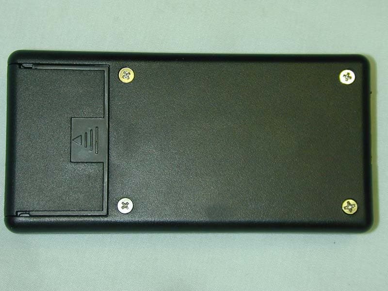
Click to zoom
Application Details
- Equipment Class
- DXX - Part 15 Low Power Communication Device Transmitter
- Date of Grant
- Jan 03, 2002
- Application Purpose
- Original Equipment
- Date of Application
- Jan 03, 2002
- Equipment Note
- Minion 701 transmitter
- Frequency Range
- 915.00000000 - 915.00000000
- Company
- AFX Technology Group
- Country
- United States
Documents & Files
Document Text
Text extracted from the exhibit documents filed with the FCC. Open a document above to read the original.
Users Manual
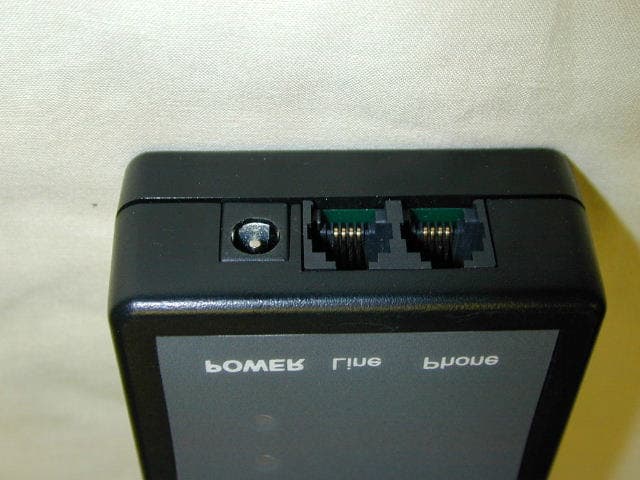
Minion 701 Feature Narrative and Installation Guide WARNING: “THIS EQUIPMENT COMPLIES WITH PART 15 OF THE FCC RULES. ANY CHANGES OR MODIFICATIONS NOT EXPRESSLY APPROVED BY THE MANUFACTURER COULD VOID THE USER’S AUTHORITY TO OPERATE THE EQUIPMENT.” Minion 701 Hardware Description The Minion701 is designed primarily as a power outage notification device. The hardware requirements of this device are a close approximation of the requirements of a MinionNet POTS Gateway. Hardware features specific to this application include battery-powered operation, a user interface lighted pushbutton and the physical form-factor. The complete product consists of a Minion 701 board and Telco Modem module in a plastic enclosure, a wall-wart power transformer and a modular cable to connect to a telephone line. User interface consists of a ½ inch square, lighted momentary pushbutton switch. Electrical interface consists of a 2.1 mm barrel connector for the external power supply and a dual RJ-11 modular telephone jack. The enclosure is a 28mm X 66 mm X 90 mm black ABS plastic enclosure with a door for the 9V battery. A flat insert in one end provides openings for the telephone and power connectors. A square hole in the center of the top surface is used by the lighted pushbutton. A recessed area on the top surrounding the button opening provides for application of an identifying label. External Power Supply The external power will be provided by an unregulated 9VDC wall transformer. This power supply will provide the operational power for the device and will also be used to detect line voltage fluctuations (brownouts and blackouts). The rated current from the transformer will be 200 mA. It is necessary to load the transformer to a significant percentage of its rating in order to ensure that the output voltage is proportional to the line voltage. The minion device will normally represent an insignificant load. The voltage measurement circuit will include a 100 ohm, 1 watt resistive divider. This will load the transformer to 50% of its rating and minimize the effect of load changes as the modem is turned on or off. The external power supply connects to the device with a 2.1 mm barrel connector with (+) on the center pin. Battery The battery will be a 9V alkaline primary cell. Typical ratings for an industrial alkaline battery show a life of 6 hours with a constant load of 100 ohms and an end-of-life voltage of 5.4 volts. Therefore, the average voltage is about 7.5 volts, average current is about 75 mA and capacity would be about 450 mA-Hours. Since this is a 3.3 volt design and we use a low- dropout regulator the actual life may more than double this figure. Modem current is listed as 21 mA max at 3.3 volts during operation and 55 uA max during power-down. The duration of an outage notification call will be approximately 30 seconds which will be the only time that the full-power load will be presented to the battery. Minion current requirements are 7 mA at 3.3 volts and 30 uA during sleep with the realtime clock running. Normal MinionNet operations turn the radio transceiver on for one second every two minutes when operating on battery power. The table shows estimated device longevity while operating on battery power. The last three columns show a life expectancy for the battery after using the modem for three different amounts of time. All of these numbers should be viewed as worst-case estimates; performance in real-world situations should be significantly better Modem Use During Normal Sleep Maximum Sleep Normal Sleep (1 : 120) Light Sleep (1 : 60) Continuous Calling 10 minutes 2 hours 6 hours Battery 450 mA-H 450 mA-H 450 mA-H 450 mA-H 445 mA-H 394 mA-H 282 mA-H Minion 30 uA 88 uA 147 uA 7 mA 88 uA 88 uA 88 uA Modem 55 uA 55 uA 55 uA 21 mA 55 uA 55 uA 55 uA Lifetime 5294 hours (220 days) 3147 hours (131 days) 2239 hours (93 days) 16 hours 3112 hours (130 days) 2775 hours (115 days) 1972 hours (82 days) To summarize: 1) The battery is only used while the main power is disconnected. 2) If the external power is on continuously the battery will last for its rated shelf life. 3) The battery life expectancy without external power is four (4) months. 4) Each hour of modem use during a power failure will reduce that expectancy by eleven (11) days. Power Supply The power supply section of the device provides for both external (wall) and internal (battery) operation. These nominal 9V supplies are regulated down to 3.3V by a Low Dropout analog regulator. Diode protection ensures that reverse connections will not damage the device. The protection diodes also ensure that power is supplied only by the wall transformer during normal operation. The transformer voltage being slightly higher than the battery voltage reverse-biases the battery protection diode and ensures that no current flows from the battery. Resistive dividers are used to establish measurement points for A/D converters used to measure the voltages of each supply. The measurement points must be between 0 and 3.3V, the range of the A/D converter using the regulated Vdd as a reference. A 100 ohm, 1 watt divider chain scales the external supply to 1/4 of its value and provides a load for the transformer. A series diode protects the analog input against reverse connection or inadvertent use of an AC transformer. A 1 Mohm divider scales the battery to 1/4 of its value and presents an insignificant continuous drain on the battery. A 0.1 uF capacitor is used to provide charge storage at the measurement point to ensure accurate measurements by the A/D converter. A series diode protects against accidental battery reversal. Microcontroller The microcontroller is a PIC controller from Microchip Technologies. The single-chip controller combines processor, flash program store, EEPROM non-volatile data storage, RAM memory, clock oscillator, real- time clock, parallel I/O ports, serial I/O and A/D converters. The asynchronous serial I/O port provides communication with the m…
Text truncated - open the document above for the full version.
Cover Letter(s)
Response to TCB findings FCC ID: P22TM701V00 Hi Davida, The following issues have been identified: 1. The radiated emissions setup photos show the unit with no wires attached. All radiated emissions measurements must be performed with all ports populated with cables of typical length. Please provide test data for the unit with cables attached. Response – revised test report supplied. 2. Please provide data responsive to the 15.31(e) requirement for supply voltage variations. Response – revised test report supplied. 3. Please provide a bandwidth plot of the fundamental. Response – revised test report supplied. 4. Please confirm that a peak detector was used for the fundamental emission level in the table on the test report page 12 of 17 as reported at the bottom of the table and not the average detector reported in the header to the table. Response – revised test report supplied. 5. The photographs of the daughter card (#2 and #3 internal) are unacceptably out of focus. Please provide new, focused, front and back pictures of the daughter card. Response – new photos supplied. 6. The operational description was not adequate, but I will cut some of the wording out of the manual that will suffice. 7. Please supply details of the label material and adhesive. Response - UL litho permanent, Silver polyester permanent, Standard permanent adhesive 8. What is the status of the Part 68 registration as I note the label does not include the Part 68 registration ID? Response – Part 68 application in progress. Best regards Barry C. Quinlan Certification & Telecom Manager ------------------------------------------------------------------------------- Curtis-Straus LLC Voice: 978.486.8880 x270 527 Great Road Fax: 978.486.8828 Littleton, MA 01460 http://www.curtis-straus.com --------------------------------------------------------------------------------
External Photos
External photos
ID Label/Location Info
FCC Label
Internal Photos
Internal photos
Operational Description
Minion 701 Feature Narrative and Installation Guide WARNING: “THIS EQUIPMENT COMPLIES WITH PART 15 OF THE FCC RULES. ANY CHANGES OR MODIFICATIONS NOT EXPRESSLY APPROVED BY THE MANUFACTURER COULD VOID THE USER’S AUTHORITY TO OPERATE THE EQUIPMENT.” Minion 701 Hardware Description The Minion701 is designed primarily as a power outage notification device. The hardware requirements of this device are a close approximation of the requirements of a MinionNet POTS Gateway. Hardware features specific to this application include battery-powered operation, a user interface lighted pushbutton and the physical form-factor. The complete product consists of a Minion 701 board and Telco Modem module in a plastic enclosure, a wall-wart power transformer and a modular cable to connect to a telephone line. User interface consists of a ½ inch square, lighted momentary pushbutton switch. Electrical interface consists of a 2.1 mm barrel connector for the external power supply and a dual RJ-11 modular telephone jack. The enclosure is a 28mm X 66 mm X 90 mm black ABS plastic enclosure with a door for the 9V battery. A flat insert in one end provides openings for the telephone and power connectors. A square hole in the center of the top surface is used by the lighted pushbutton. A recessed area on the top surrounding the button opening provides for application of an identifying label. External Power Supply The external power will be provided by an unregulated 9VDC wall transformer. This power supply will provide the operational power for the device and will also be used to detect line voltage fluctuations (brownouts and blackouts). The rated current from the transformer will be 200 mA. It is necessary to load the transformer to a significant percentage of its rating in order to ensure that the output voltage is proportional to the line voltage. The minion device will normally represent an insignificant load. The voltage measurement circuit will include a 100 ohm, 1 watt resistive divider. This will load the transformer to 50% of its rating and minimize the effect of load changes as the modem is turned on or off. The external power supply connects to the device with a 2.1 mm barrel connector with (+) on the center pin. Battery The battery will be a 9V alkaline primary cell. Typical ratings for an industrial alkaline battery show a life of 6 hours with a constant load of 100 ohms and an end-of-life voltage of 5.4 volts. Therefore, the average voltage is about 7.5 volts, average current is about 75 mA and capacity would be about 450 mA-Hours. Since this is a 3.3 volt design and we use a low- dropout regulator the actual life may more than double this figure. Modem current is listed as 21 mA max at 3.3 volts during operation and 55 uA max during power-down. The duration of an outage notification call will be approximately 30 seconds which will be the only time that the full-power load will be presented to the battery. Minion current requirements are 7 mA at 3.3 volts and 30 uA during sleep with the realtime clock running. Normal MinionNet operations turn the radio transceiver on for one second every two minutes when operating on battery power. The table shows estimated device longevity while operating on battery power. The last three columns show a life expectancy for the battery after using the modem for three different amounts of time. All of these numbers should be viewed as worst-case estimates; performance in real-world situations should be significantly better Modem Use During Normal Sleep Maximum Sleep Normal Sleep (1 : 120) Light Sleep (1 : 60) Continuous Calling 10 minutes 2 hours 6 hours Battery 450 mA-H 450 mA-H 450 mA-H 450 mA-H 445 mA-H 394 mA-H 282 mA-H Minion 30 uA 88 uA 147 uA 7 mA 88 uA 88 uA 88 uA Modem 55 uA 55 uA 55 uA 21 mA 55 uA 55 uA 55 uA Lifetime 5294 hours (220 days) 3147 hours (131 days) 2239 hours (93 days) 16 hours 3112 hours (130 days) 2775 hours (115 days) 1972 hours (82 days) To summarize: 1) The battery is only used while the main power is disconnected. 2) If the external power is on continuously the battery will last for its rated shelf life. 3) The battery life expectancy without external power is four (4) months. 4) Each hour of modem use during a power failure will reduce that expectancy by eleven (11) days. Power Supply The power supply section of the device provides for both external (wall) and internal (battery) operation. These nominal 9V supplies are regulated down to 3.3V by a Low Dropout analog regulator. Diode protection ensures that reverse connections will not damage the device. The protection diodes also ensure that power is supplied only by the wall transformer during normal operation. The transformer voltage being slightly higher than the battery voltage reverse-biases the battery protection diode and ensures that no current flows from the battery. Resistive dividers are used to establish measurement points for A/D converters used to measure the voltages of each supply. The measurement points must be between 0 and 3.3V, the range of the A/D converter using the regulated Vdd as a reference. A 100 ohm, 1 watt divider chain scales the external supply to 1/4 of its value and provides a load for the transformer. A series diode protects the analog input against reverse connection or inadvertent use of an AC transformer. A 1 Mohm divider scales the battery to 1/4 of its value and presents an insignificant continuous drain on the battery. A 0.1 uF capacitor is used to provide charge storage at the measurement point to ensure accurate measurements by the A/D converter. A series diode protects against accidental battery reversal. Microcontroller The microcontroller is a PIC controller from Microchip Technologies. The single-chip controller combines processor, flash program store, EEPROM non-volatile data storage, RAM memory, clock oscillator, real- time clock, parallel I/O ports, serial I/O and A/D converters. The asynchronous serial I/O port provides communication with the m…
Text truncated - open the document above for the full version.
Test Report
Nemko Test Report: 1L0620RUS1 Applicant: AFX Technology Group International, Inc. 4407 Beltwood Parkway, Suite 108 Dallas, Texas 75244 Equipment Under Test: MinionNet Telco Gateway (E.U.T.) In Accordance With: FCC Part 15, Subpart C, 15.249 For 900 MHz Transmitters Tested By: NEMKO Dallas Inc. 802 N. Kealy Ave Lewisville, TX 75057-3136 Authorized By: Tom Tidwell, EMC/Wireless Group Manager Date: 11/27/01 Total Number of Pages: 18 Nemko Dallas FCC PART 15, SUBPART C FOR 900 MHz TRANSMITTERS PROJECT NO.: 1L0620RUS1 EQUIPMENT:MinionNet Telco Gateway Page 2 of 18 Table Of Contents Section 1. Summary Of Test Results .......................................................................3 Section 2. General Equipment Specification ...........................................................5 Section 3. Powerline Conducted Emissions ............................................................8 Section 4. Radiated Emissions .................................................................................11 Section 5. Test Equipment List .................................................................................15 ANNEX A - TEST DIAGRAMS ....................................................................................16 Nemko Dallas FCC PART 15, SUBPART C FOR 900 MHz TRANSMITTERS PROJECT NO.: 1L0620RUS1 EQUIPMENT:MinionNet Telco Gateway Page 3 of 18 Section 1. Summary Of Test Results Manufacturer: AFX Technology Group Model No.: MinionNet Teleco Gateway Serial No.: None General: All measurements are traceable to national standards. These tests were conducted on a sample of the equipment for the purpose of demonstrating compliance with FCC Part 15.249. All tests were conducted using measurement procedure ANSI C63.4-1992. Radiated Emissions were made on an open area test site. New Submission Production Unit Class II Permissive Change Pre-Production Unit THIS TEST REPORT RELATES ONLY TO THE ITEM(S) TESTED. THE FOLLOWING DEVIATIONS FROM, ADDITIONS TO, OR EXCLUSIONS FROM THE TEST SPECIFICATIONS HAVE BEEN MADE. See “ Summary of Test Data”. NVLAP LAB CODE: 100351-0 TESTED BY: ___Lance Walker ________________________ DATE: ___11/27/01_______ NEMKO Dallas Inc. authorizes the above named company to reproduce this report provided it is reproduced in its entirety and for use by the company’s employees only. Any use which a third party makes of this report, or any reliance on or decisions to be made based on it, are the responsibility of such third parties. NEMKO Dallas Inc. accepts no responsibility for damages, if any, suffered by any third party as a result of decisions made or actions based on this report. This report applies only to the items tested. Nemko Dallas FCC PART 15, SUBPART C FOR 900 MHz TRANSMITTERS PROJECT NO.: 1L0620RUS1 EQUIPMENT:MinionNet Telco Gateway Page 4 of 18 Summary Of Test Data NAME OF TEST PARA. NO. RESULT Conducted Emissions 15.207 Complies Radiated Emissions 15.249 Complies Footnotes: None Nemko Dallas FCC PART 15, SUBPART C FOR 900 MHz TRANSMITTERS PROJECT NO.: 1L0620RUS1 EQUIPMENT:MinionNet Telco Gateway Page 5 of 18 Section 2. General Equipment Specification Frequency Range: Single fixed channel Operating Frequency(ies) of Sample: 915 MHz Tunable Bands: N/A Number of Channels: One Channel Spacing: N/A User Frequency Adjustment: N/A Integral Antenna Yes No Nemko Dallas FCC PART 15, SUBPART C FOR 900 MHz TRANSMITTERS PROJECT NO.: 1L0620RUS1 EQUIPMENT:MinionNet Telco Gateway Page 6 of 18 Description of Modification for Class II Permissive Change Modifications Made During Testing Nemko Dallas FCC PART 15, SUBPART C FOR 900 MHz TRANSMITTERS PROJECT NO.: 1L0620RUS1 EQUIPMENT:MinionNet Telco Gateway Page 7 of 18 Theory of Operation The EUT is a short-range wireless device designed to provide a wireless connection to the PSTN for very short data bursts. The device could be used in a variety of applications System Diagram A 1 B Nemko Dallas FCC PART 15, SUBPART C FOR 900 MHz TRANSMITTERS PROJECT NO.: 1L0620RUS1 EQUIPMENT:MinionNet Telco Gateway Page 8 of 18 Section 3. Powerline Conducted Emissions NAME OF TEST: Powerline Conducted Emissions PARA. NO.: 15.207 TESTED BY: Clay Daniel DATE: 11/26/01 Minimum Standard: Frequency Maximum Powerline Conducted RF Voltage (MHz) (μV) (dBμV) 0.45 - 30.0 250 48 Test Results: Complies. See attached data. Measurement Data: See attached data. Method of Measurement: (Procedure ANSI C63.4-1992) Measurements were made using a spectrum analyzer with 10 kHz RBW, Peak Detector. Any emissions that are close to the limit are measured using a test receiver with 10 kHz bandwidth, CISPR Quasi-Peak Detector. Nemko Dallas FCC PART 15, SUBPART C FOR 900 MHz TRANSMITTERS PROJECT NO.: 1L0620RUS1 EQUIPMENT:MinionNet Telco Gateway Page 9 of 18 Dallas Headquarters: 802 N. Kealy Lewisville, TX 75057 Tel: (972) 436-9600 NEMKO Dallas, Inc. Fax: (972) 436-2667 Conducted Emissions Powerline Voltage Measurement CompleteXJob # : 1L0620RTest # : CEPV-01 PreliminaryPage1of1 Client Name :AFX Technology Group EUT Name :MinionNet Telco Gateway EUT Model # :701 EUT Part # :None Given EUT Serial # :FE00-020E EUT Config. :EUT powered by AC to DC convertor, loopback cable connected to RJ-11 ports. Normal mode - modem on. Specification :CFR 47, Part 15, Subpart B, Class B Reference : 15.107 Transducer # :545Temp. (deg. C) :24Date : 11/26/01 HP Filter # :758Humidity (%) :42Time : 1430 Cable 1 # :1553EUT Voltage :115VacStaff : Clay Daniel Cable 2 # :970EUT Frequency :60HzLocation : Lab 2 Detector 1 # :1502Peak Bandwidth:10kHzPhoto ID: 1L0620E CEPV-01 Detector 2 # :1022QP Bandwidth10kHz Limiter # :1603Avg. Bandwidth10kHz Meas.EUTDetectorLimitMeterPathTransducer CorrectedSpec.limitCR/SLPass Freq. TestTypeTypeReadingLossFactorReading(dBuV)Diff.Fail (MHz)Point(P,QP, A)(QP, A)(dBuV)(dB)(dB)(dBuV)Q.P.Avg.(dB)Unc.Comment 0.691NPQP17.90.00.017.948.0NA-30.1Pass 8.161NPQP18.40.00.018.448.0NA-29.6Pass 16NPQP19.60.00.019.648.0NA-28.4Pass 20NPQP17.60.00.017.648.0NA-30.4Pass 24NPQP18.30.00.018.…
Text truncated - open the document above for the full version.
Test Setup Photos
Nemko Dallas FCC PART 15, SUBPART C FOR 900 MHz TRANSMITTERS PROJECT NO.: 1L0620RUS1 EQUIPMENT:MinionNet Telco Gateway Page 14 of 18 Radiated Photographs (Worst Case Configuration) FRONT VIEW REAR VIEW
Contact Information
Applicant
Brian K McMillin(VP)
Test Firm
Nemko Dallas, Inc.Michael Cantwell
Technical Specifications
| # | Rule Parts | Frequency Range | Power Output |
|---|---|---|---|
| 1 | 15C | 915 MHz - 915 MHz | - |
Other Applications from AFX Technology Group
P22TM851V01
Nov 13, 2002Power Outage Transmitter
Equipment Class
DXX - Part 15 Low Power Communication Device Transmitter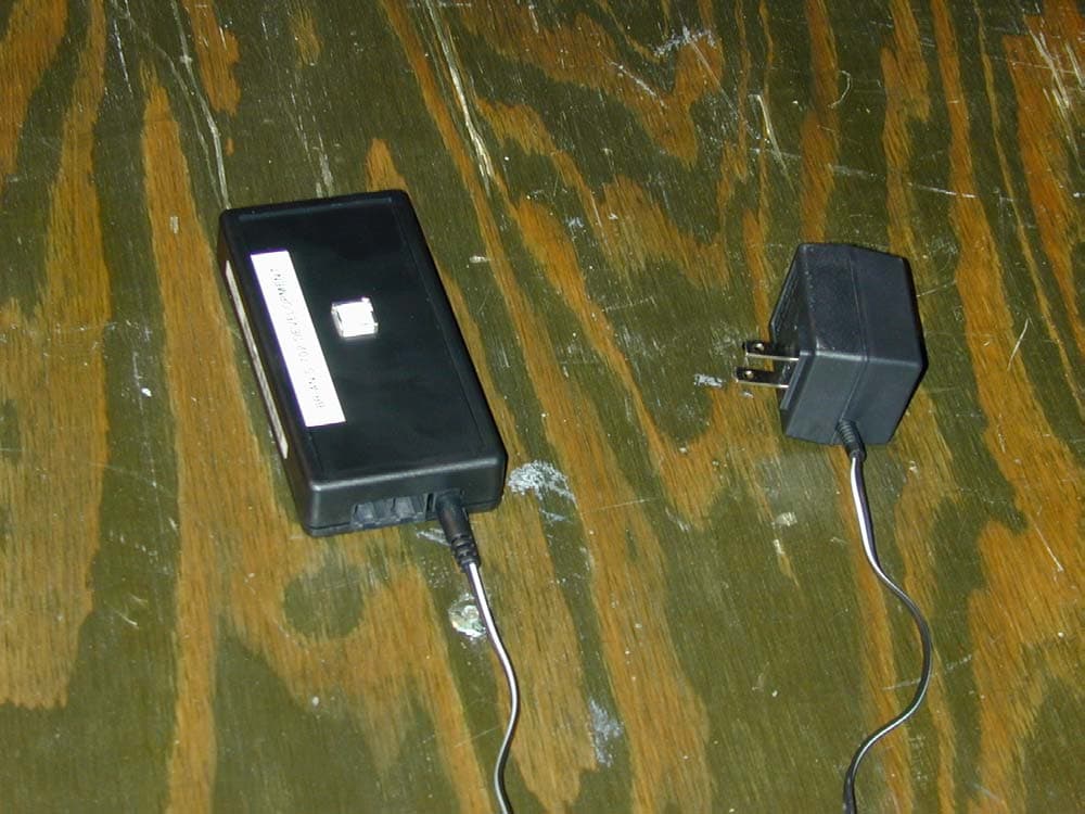
P22TM702V00
Mar 06, 2002Low Power Transmitter
Equipment Class
DXX - Part 15 Low Power Communication Device Transmitter