P22TM851V01Power Outage Transmitter
AFX Technology Group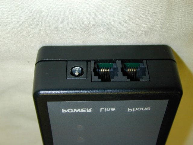
Click to zoom
Application Details
- Equipment Class
- DXX - Part 15 Low Power Communication Device Transmitter
- Date of Grant
- Nov 13, 2002
- Application Purpose
- Original Equipment
- Date of Application
- Nov 13, 2002
- Equipment Note
- Power Outage Transmitter
- Frequency Range
- 918.00000000 - 918.00000000
- Company
- AFX Technology Group
- Country
- United States
Documents & Files
Document Text
Text extracted from the exhibit documents filed with the FCC. Open a document above to read the original.
Users Manual
TXU Energy (Certificate No. 10004) is not the same company as TXU Electric & Gas and is not regulated by the Public Utility Com- mission of Texas, and you do not have to buy TXU Energy's products to continue to receive quality regulated services from TXU Elec- tric & Gas. TXU Outage Notification User Guide 2 Table of Contents 1.Installation ......................................................................................3 2.Device Relocation.......................................................................... 4 3.Initial Online Access Instruction .....................................................4 4.Status Indicator Light Conditions.................................................... 4 5.Accessories ....................................................................................5 6.FCC Statements .............................................................................5 3 USER GUIDE Use the following procedure to install and operate the TXU Outage Notification Device model 851. 7.Installation Step 1.There are three components to your Outage Notification installation package: the device, a phone cord, and a small AC adapter (which is located in the small box) Step 2.Remove the AC adapter from the box Step 3.Visually inspect all pieces for damage. (Note: You may notice the green status indicator light on the device blinking approximately every 15 seconds – this is normal.) Step 4.Insert one end of the phone cord into the “Phone Line IN” port of the device. Step 5.Insert the round plug end of the AC adapter cord into the “POWER” port of the device. Step 6.Locate a power outlet near an analog telephone jack (Typically a fax line, not a digital or ISDN phone line). You should select a 110 Volt power outlet that is not controlled by a wall switch and is on the electrical circuit you wish to monitor. The telephone jack and wall out- let should be within approximately seven feet of each other. Step 7.Insert the free end of the phone cord into the telephone jack. Step 8.Plug the AC adapter into the wall outlet. Note:The green status indicator light will turn ON continuously for a few seconds, then start blinking to indicate that it is contacting TXU Energy. After sending a short message, the green status indicator light will be continuously ON – Your AC power is ON and the service is activated.) If you wish to connect a fax machine or an answering machine, simply use the jack marked “Phone Line OUT” on the device. Step 9.Within fifteen minutes you should receive the following message from the service, “Wel- come to TXU Outage Notification! Your service has been successfully activated.” This message will be sent to the contacts setup during the enrollment process. If you do not receive a Welcome message within fifteen minutes, please call TXU Outage Notification Customer Service at 1-888-398-8711 or check the contact information setup on the Outage Notification web site at: http://www.txuenergy.com/energyserv/outagenotification For your convenience there is a “Velcro” strip included in the kit. If you wish to attach the device to the wall or under a table, simply remove the protective film from one side of the Velcro strip and apply it to the back of the device (do not cover the battery cover door). Remove the second protective film from the Velcro strip and press the device in place. 4 8.Device Relocation Use the following procedure to move the device to another location within the same building or structure. Step 1.First select the new location. Step 2.Remove the phone cord from the “Phone Line IN” port of the device. Step 3.Remove the round plug end of the AC adapter cord from the power port of the device. Step 4.Move all components to the new location. Step 5.Plug to the phone cord into the (analog) telephone wall outlet. Step 6.Plug the AC adapter into the 110 Volt outlet at the new location (again, be sure that the outlet is not controlled by a wall switch.) Step 7.Insert the free end of the phone cord into the “Phone Line IN” port of the device. Step 8.Insert the round plug end of the AC adapter cord into the “POWER” port of the device. Step 9.After a moment, the green status indicator light should turn ON continuously. You should not receive any notifications from TXU Energy. Note:To avoid possible regulated utility charges for reporting a false outage be sure to FIRST disconnect the round plug end of the AC adapter cord from the device before unplugging the AC adapter from the wall outlet. 9.Initial Online Access Instruction Please note that your initial user ID for online account access is your business phone number that you provided when you register for the service. Your initial password is changeme. For security purpose, please reset your user ID and password after you log in the first time. 10.Status Indicator Light Conditions The following conditions are indicates by the light status indicator on the device: ConditionRed (top) LightGreen (bottom Light AC “ON” Good Battery (Normal Operation)OFFON AC adapter removed, Good Battery (Moving)OFFSlow Blink Power Out, Notification PendingTwo short blinks every 15 seconds OFF Device attempting to callOFFFast Blinking Power OutageShort Blink every 15 secondsOFF AC “ON” Low BatteryONOFF No AC and Dead BatteryOFFOFF 5 11.Accessories •“CAUTION - To reduce the risk of fire, use only No. 26 AWG or larger telecommu- nication line cord or equivalent.” •“ATTENTION - Pour réduire les risques d'incendie, utiliser uniquement des con- ducteurs de télécommunications 26 AWG au de section supérleure." •The power supply required for this must be a UL Listed, Class 2 power supply with input rating 120 Vac and output rating 9 Vdc, 200 mA. 12.FCC Statements Part 15 This equipment has been tested and found to comply with the limits for a Class B digital device, pursuant to Part 15 of the FCC Rules. These limits are designed to provide reasonable protection against harmful interference in a residential installation. This equipment generates, …
Text truncated - open the document above for the full version.
Block Diagram
AFX Technology Group International Inc. Dallas, Texas H100 Rev D and Minion 851 Rev A BLOCK DIAGRAM AUTH: LWM DateDWG NOREV 21 Oct 02 AFX-BLK-001A 1 OF 1 Antenna OUT Antenna IN Green Status Indicator Light Red Status Indicator Light Test Push Button 32 KHz 5.068 MHz 12.000 MHz PSTN 9V Battery 9V DC Power Supply and Level Detect Flame Retardent Plastic Enclosure Modem Transceiver Electric Path Data Path Microcontroller H100 Rev D Transceiver Daughter Board Minion 851 Rev A Main Board
External Photos
______________________________________________________________________________________ ______________________________________________________________________________________
ID Label/Location Info
FCC ID: P22TMHW002 This device complies with Part 15 of the FCC Rules. Operation is subject to the following two conditions: (1) this device may not cause harmful interference, and (2) this device must accept any interference received, including interference that may cause undesired operation. 13.0 cm 6.5 cm 2.0 cm 2.0 cm Back of Device Label Material UL litho permanent, silver polyester permanent. Standard permanent adhesive. AFX Technology Group International Inc. Dallas, Texas MINION 851 REV A AND H100 REV D FCC PART 15 LABEL Drafter: LWM DateDWG NOREV 22 Oct 02 AFX-BLK-002A 1 OF 1
Operational Description
Technology Group International, Inc. 4407 N. Beltwood Parkway, Suite 108 Dallas, Texas 75244-3246 AFX Proprietary and Confidential Material Model 851 Product Description 1.Overview The Minion 851 Rev A main board with transciever H100 Rev D is design as a power outage notification device. The hardware requirements of this device are a close approximation of the requirements set forth for a TM702V00 gateway device, FCC ID P22TM702V00. Hardware features specific to this application include: •Battery-powered operation •User interface test push button •Status light indicators •Physical form-factor. 1.1Product Package Contents The 851 product package consists of: •851 circuit board which includes a built-in microcontroller, modem, circuit protection and external power supply, battery, and telco RJ-11 connectors. •H100 Rev D transceiver operating at 918 MHz. •User interface consists of a ½ inch square push button switch and two light indicators (red and green). •The enclosure is a 65mm X 133mm X 29mm black ABS plastic enclosure with a door for the 9V battery. A flat insert in one end provides openings for the telephone and power connectors. A square hole in the center of the top surface is used by the push button. A recessed area on the top surrounding the button opening provides for application of an identifying label. 2.Power Source and Requirements 2.1External Power Supply The external power will be provided by an unregulated 9VDC wall transformer. This power supply will provide the operational power for the device and will also be used to detect line voltage fluctuations (brownouts and blackouts). The rated current from the transformer will be 200 mA. It is necessary to load the transformer to a significant percentage of its rating in order to ensure that the output voltage is proportional to the line voltage. The device will normally represent an insignificant load. The voltage measurement circuit will include a 100 ohm, 1 watt resistive divider. This will load the transformer to 50% of its rating and minimize the effect of load changes as the modem is turned on or off. The external power supply connects to the device with a 2.1 mm barrel connector with (+) on the center pin. AFX Proprietary and Confidential Material 2 2.2Battery The battery will be a 9V alkaline primary cell. Typical ratings for an industrial alkaline battery show a life of 6 hours with a constant load of 100 ohms and an end-of-life voltage of 5.4 volts. Therefore, the average voltage is about 7.5 volts, average current is about 75 mA and capacity would be about 450 mA-Hours. Since this is a 3.3 volt design and we use a low-dropout regulator the actual life may more than double this figure. The table shows estimated device longevity while operating on battery power. The last three columns show a life expectancy for the battery after using the modem for three different amounts of time. All of these numbers should be viewed as worst-case estimates; performance in real-world situations should be significantly better To summarize: •The battery is only used while the main power is disconnected. •If the external power is on continuously the battery will last for its rated shelf life. •The battery life expectancy without external power is four (4) months. •Each hour of modem use during a power failure will reduce that expectancy by eleven (11) days. 2.3Device Component Requirements 2.3.1Transceiver Transceiver peak current is specified as 26 mA which is well within the drive capability of the output pin. Empirical results show that the operating voltage is typically 7.0V Vdd This represents a slight penalty, typically in reduced receiver sensitivity that can be eliminated by powering the transceiver directly from the Vdd rail in applications that do not require maximum power conservation. 2.3.2Modem The modem current is listed as 21 mA max at 3.3 volts during operation and 55 uA max during power-down. The duration of an outage notification call will be approximately 30 seconds which will be the only time that the full-power load will be presented to the battery. 2.3.3Power Regulator The power supply section of the device provides for both external (wall) and internal (battery) operation. These nominal 9V supplies are regulated down to 3.3V by a Low Dropout analog regulator. Diode protection ensures that reverse connections will not Maximum Sleep Normal Sleep (1: 120) Light Sleep (1: 60) Continuous Calling Modem Use During Normal Sleep 10 minutes2 hours6 hours Battery450 mA-H450 mA-H450 mA-H450 mA-H445 mA-H394 mA-H282 mA-H Main Board30 uA88 uA147 uA7 mA88 uA88 uA88 uA Modem55 uA55 uA55 uA21 mA55 uA55 uA55 uA Lifetime5294 hours (220 days) 3147 hours (131 days) 2239 hours (93 days) 16 hours3112 hours (130 days) 2775 hours (115 days) 1972 hours (82 days) AFX Proprietary and Confidential Material damage the device. The protection diodes also ensure that power is supplied only by the wall transformer during normal operation. The transformer voltage being slightly higher than the battery voltage reverse-biases the battery protection diode and ensures that no current flows from the battery. •Resistive dividers are used to establish measurement points for A/D converters used to measure the voltages of each supply. The measurement points must be between 0 and 3.3V, the range of the A/D converter using the regulated Vdd as a reference. •A 100 ohm, 1 watt divider chain scales the external supply to 1/4 of its value and provides a load for the transformer. A series diode protects the analog input against reverse connection or inadvertent use of an AC transformer. •A 1 Mohm divider scales the battery to 1/4 of its value and presents an insignificant continuous drain on the battery. A 0.1 uF capacitor is used to provide charge storage at the measurement point to ensure accurate measurements by the A/D converter. A series diode protects against accidental battery reversal. 2.3.4Microcontroller Low-power consumption: •- < 0.6 mA typical @ 3V, 4…
Text truncated - open the document above for the full version.
Test Report
Nemko Test Report: 2L0493RUS1 Applicant: AFX Technology Group, Inc. 4407 N. Beltwood Parkway Suite #108 Dallas, TX 75244 Equipment Under Test: Model 851 (E.U.T.) In Accordance With: FCC Part 15, Subpart C, 15.249 For 900 MHz Transmitters Tested By: Nemko Dallas Inc. 802 N. Kealy Lewisville, Texas 75057-3136 Authorized By: Tom Tidwell, Wireless Group Manager Date: 10/21/02 Total Number of Pages: 18 Nemko Dallas FCC PART 15, SUBPART C FOR 900 MHz TRANSMITTERS PROJECT NO.: ANNEX A EQUIPMENT: FCC ID: Page 2 of 18 Table Of Contents Section 1. Summary Of Test Results ...............................................................................3 Section 2. General Equipment Specification ...................................................................5 Section 3. Powerline Conducted Emissions ....................................................................7 Section 4. Radiated Emissions .........................................................................................11 Section 5.Test Equipment List .........................................................................................15 ANNEX A TEST DIAGRAMS ......................................................................................16 Nemko Dallas FCC PART 15, SUBPART C FOR 900 MHz TRANSMITTERS PROJECT NO.: ANNEX A EQUIPMENT: FCC ID: Page 3 of 18 Section 1. Summary Of Test Results Manufacturer: AFX Technology Group, Inc Model No.: 851 Serial No.: None General: All measurements are traceable to national standards. These tests were conducted on a sample of the equipment for the purpose of demonstrating compliance with FCC Part 15.249. All tests were conducted using measurement procedure ANSI C63.4-1992. Radiated Emissions were made on an open area test site. New Submission Production Unit Class II Permissive Change Pre-Production Unit D S C Equipment Code THIS TEST REPORT RELATES ONLY TO THE ITEM(S) TESTED. THE FOLLOWING DEVIATIONS FROM, ADDITIONS TO, OR EXCLUSIONS FROM THE TEST SPECIFICATIONS HAVE BEEN MADE. See “ Summary of Test Data”. NVLAP LAB CODE: 100351-0 Nemko Dallas Inc. authorizes the above named company to reproduce this report provided it is reproduced in its entirety and for use by the company’s employees only. Any use which a third party makes of this report, or any reliance on or decisions to be made based on it, are the responsibility of such third parties. Nemko Dallas Inc. accepts no responsibility for damages, if any, suffered by any third party as a result of decisions made or actions based on this report. This report applies only to the items tested. Nemko Dallas FCC PART 15, SUBPART C FOR 900 MHz TRANSMITTERS PROJECT NO.: ANNEX A EQUIPMENT: FCC ID: Page 4 of 18 Summary Of Test Data NAME OF TEST PARA. NO. RESULT Conducted Emissions 15.207 Complies Radiated Emissions 15.249 Complies Nemko Dallas FCC PART 15, SUBPART C FOR 900 MHz TRANSMITTERS PROJECT NO.: ANNEX A EQUIPMENT: FCC ID: Page 5 of 18 Section 2. General Equipment Specification Frequency Range: 918 MHz Operating Frequency(ies) of Sample: 918 MHz Tunable Bands: N/A Number of Channels: 1 Channel Spacing: N/A User Frequency Adjustment: None Integral Antenna Yes No Nemko Dallas FCC PART 15, SUBPART C FOR 900 MHz TRANSMITTERS PROJECT NO.: ANNEX A EQUIPMENT: FCC ID: Page 6 of 18 Description of Operation The device is a single frequency radio used for power outage notification. System Diagram Nemko Dallas FCC PART 15, SUBPART C FOR 900 MHz TRANSMITTERS PROJECT NO.: ANNEX A EQUIPMENT: FCC ID: Page 7 of 18 Section 3. Powerline Conducted Emissions NAME OF TEST: Powerline Conducted Emissions PARA. NO.: 15.207 TESTED BY: David Light DATE: Minimum Standard: Frequency Maximum Powerline Conducted RF Voltage (MHz) (μV) (dBμV) 0.45 - 30.0 250 48 Test Results: Complies. See attached graph(s). Measurement Data: See attached graph(s). Method of Measurement: (Procedure ANSI C63.4-1992) Measurements were made using a spectrum analyzer with 10 kHz RBW, Peak Detector. Any emissions that are close to the limit are measured using a test receiver with 10 kHz bandwidth, CISPR Quasi-Peak Detector. Nemko Dallas FCC PART 15, SUBPART C FOR 900 MHz TRANSMITTERS PROJECT NO.: ANNEX A EQUIPMENT: FCC ID: Page 8 of 18 Dallas Headquarters: 802 N. Kealy Lewisville, TX 75057 Tel: (972) 436-9600 NEMKO Dallas, Inc. Fax: (972) 436-2667 Conducted Emissions Powerline Voltage Measurement CompleteXJob # : 2L0493RTest # : CEPV-01 PreliminaryPage1of2 Client Name :AFX EUT Name :Version 1 - Outage Notification EUT Model # :851 EUT Part # :NA EUT Serial # :NA EUT Config. :Tabletop - Tx full power Specification :15.207 Reference : Transducer # :1258Temp. (deg. C) :24Date : ####### HP Filter # :1555Humidity (%) :50Time : 9:00 Cable 1 # :1547EUT Voltage :115Staff : DL Cable 2 # :1534EUT Frequency :60Location : Lab 2 Detector 1 # :1036Peak Bandwidth:10kHzPhoto ID: None Detector 2 # :QP Bandwidth10kHz Limiter # :674Avg. Bandwidth10kHzLINE L2 10L2PQP17.70.00.017.748.0-30.3Pass ..\EMCShare\AUTOMATE\DATASHTS\CEP_Voltage Rev C.xls Document Control #EMC DS EM COND VOLT Nemko Dallas FCC PART 15, SUBPART C FOR 900 MHz TRANSMITTERS PROJECT NO.: ANNEX A EQUIPMENT: FCC ID: Page 9 of 18 Dallas Headquarters: 802 N. Kealy Lewisville, TX 75057 Tel: (972) 436-9600 NEMKO Dallas, Inc.Fax: (972) 436-2667 Conducted Emissions Powerline Voltage Measurement CompleteXJob # : 2L0493RTest # :CEPV-01 PreliminaryPage2of2 Client Name :AFX EUT Name :Version 1 - Outage Notification EUT Model # :851 EUT Part # :NA EUT Serial # :NA EUT Config. :Tabletop - Tx full power Specification :15.207 Reference : LINE L1 10L1PQP20.80.00.020.848.0-27.2Pass ..\EMCShare\AUTOMATE\DATASHTS\CEP_Voltage Rev C.xlsDocument Control #EMC DS EM COND VOLT Nemko Dallas FCC PART 15, SUBPART C FOR 900 MHz TRANSMITTERS PROJECT NO.: ANNEX A EQUIPMENT: FCC ID: Page 10 of 18 Conducted Photographs (Worst Case Configuration) Nemko Dallas FCC PART 15, SUBPART C FOR 900 MHz TRANSMITTERS PROJECT NO.: ANNEX A EQUIPMENT: FCC ID: Page 11 of 18 Section 4. Radiated E…
Text truncated - open the document above for the full version.
Test Setup Photos
Nemko Dallas FCC PART 15, SUBPART C FOR 900 MHz TRANSMITTERS PROJECT NO.:2L0493RUS1 EQUIPMENT:Model 851 Page 13 of 17 Radiated Photographs (Worst Case Configuration)
Contact Information
Applicant
Brian K McMillin(VP)
Test Firm
Nemko Dallas, Inc.Michael Cantwell
Technical Specifications
| # | Rule Parts | Frequency Range | Power Output |
|---|---|---|---|
| 1 | 15C | 918 MHz - 918 MHz | - |
Other Applications from AFX Technology Group
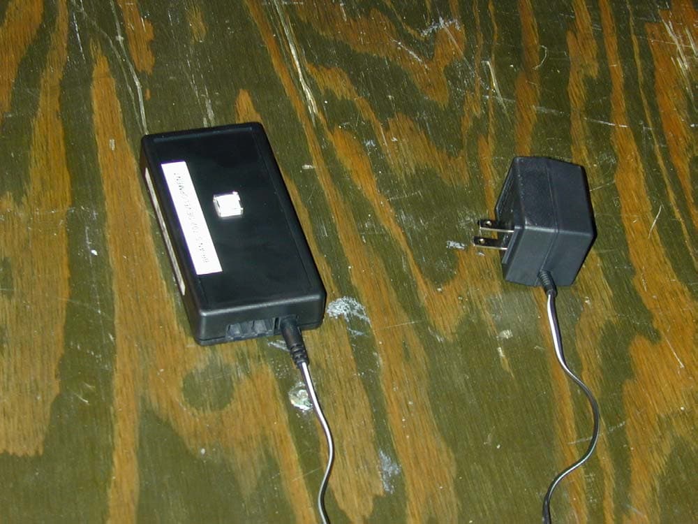
P22TM702V00
Mar 06, 2002Low Power Transmitter
Equipment Class
DXX - Part 15 Low Power Communication Device Transmitter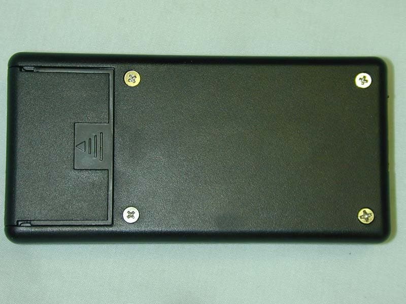
P22TM701V00
Jan 03, 2002Minion 701 transmitter
Equipment Class
DXX - Part 15 Low Power Communication Device Transmitter