P25A957267B1011CWii REACTOR Motion Controller w/MP /Wii REACTOR Motion Controller
Mad Catz, Inc.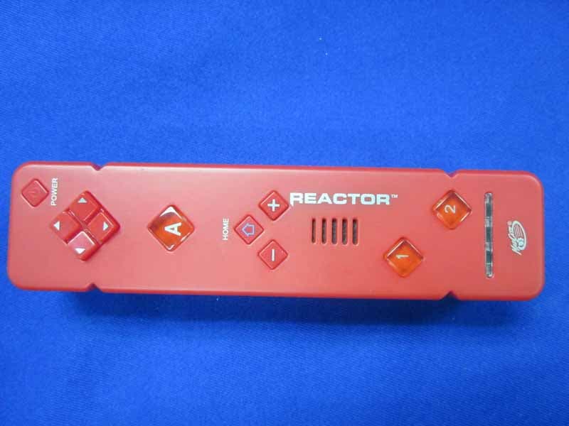
Click to zoom
Application Details
- Equipment Class
- DSS - Part 15 Spread Spectrum Transmitter
- Date of Grant
- Nov 22, 2011
- Application Purpose
- Original Equipment
- Date of Application
- Nov 21, 2011
- Equipment Note
- Wii REACTOR Motion Controller w/MP /Wii REACTOR Motion Controller
- Frequency Range
- 2402.00000000 - 2480.00000000
- Company
- Mad Catz, Inc.
- Country
- United States
Documents & Files
Document Text
Text extracted from the exhibit documents filed with the FCC. Open a document above to read the original.
Users Manual
Wii Remote Manual Page 1 of 10 Set Up of the Wii Remote The remote uses two AA batteries. Use only high quality alkaline batteries for the best game play experience and longevity of battery life. Please read the following information carefully. • Installing Batteries • Synchronizing a Wii Remote With the Wii Console • Turn the Rumble feature on or off • Check battery levels • Adjust volume of internal speaker Installing the Batteries Important Note: If you would like to use rechargeable batteries, the only type of battery recommended are Nickel Metal Hydride batteries. When it comes to using rechargeable batteries, you must follow manufacturer guidelines for safety and proper usage. Failure to do so could cause damage to the Wii Remote and void the warranty. 1. Remove the battery cover on the back of the Wii Remote and insert two AA batteries, using the plus (+) and minus (-) guides in the Wii Remote's battery compartment to insert the batteries in the proper direction. 2. Be sure to insert the minus (-) end first when inserting new batteries, and remove the plus (+) end first when replacing the batteries. 3. Replace the battery cover. Wii Remote Manual Page 2 of 10 Synchronizing the Wii Remote with the Wii Console Synchronizing the Wii Remote to a Wii console allows the Wii Remote to communicate with the console. The Wii Remote included with your system should already be synchronized to your console. However, all additional Wii Remotes you use with your system also need to be synced in order to function properly.. There are two different modes of synchronizing (syncing): • STANDARD MODE - The Standard Mode procedure is used when adding additional Wii Remotes to your system or if you want to re-synchronize your original Wii Remote. Once synchronized, the Wii Remote will stay synced to the console unless you overwrite the settings by syncing the remote to a different console. For instructions on Standard Mode syncing, please click here. • ONE TIME MODE - This mode allows you to temporarily use your remote on a Wii console other than your own, or to use a friend's remote on your console. It can also be used to change the order of the Wii Remotes, without the need to turn off the Wii console. One Time Mode does not delete the Standard Mode setting stored in the Wii Remote. In this mode, the Wii Remote will only communicate with the Wii console while the power is on. When the power is turned off, the Wii Remote will lose its sync with the Wii Console. For instructions on One Time Mode setup, please click here. Note: Only a Wii Remote in Standard Mode can turn the Wii console power ON or OFF. Standard Mode Synchronization Note: Make sure you have placed batteries in the Wii Remote (how to). 1. Press the Power button on the Wii console to turn it on. 2. Open the SD Card Slot cover on the front of the Wii console. Remove the battery cover on the back of the Wii Remote you wish to sync up. Wii Remote Manual Page 3 of 10 3. Press and release the SYNC button on the inside of the SD Card compartment on the console. Press and release the SYNC button just below the batteries on the Wii Remote. 4. When the Player LED blinking stops, the syncing is complete. The LED that is illuminated indicates the player number (1 through 4). This procedure must be followed for each additional Wii Remote added to your system. One Time Mode Synchronization Note: This mode temporarily removes Standard Mode synchronization setup for all Wii Remotes until the power of the Wii console is turned off. When the power is turned back on again, the Standard Mode settings will return. 1. Press the HOME Button on a Wii Remote that is synchronized with the Wii console. Wii Remote Manual Page 4 of 10 2. Select the Wii Remote Settings option from the Home Button menu. 3. Select the Reconnect Option. 4. Press the 1 and 2 Buttons at the same time on the Wii Remote that you want to synchronize with the console. If you are syncing multiple Wii Remotes, press the 1 and 2 Buttons on each Wii Remote immediately (without a significant pause) in the order you want them synced. The order in which you synchronize Wii Remotes determines the player order (1 through 4) for multiplayer games. The Player LED will blink during the syncing process. When the blinking stops, the connection is complete. Wii Remote Manual Page 5 of 10 Turn the Rumble feature on or off The Wii Remote has a built-in rumble device that will shake the Wii Remote at certain points while using the Wii. The following information describes how to turn this feature "on" or "off." • Not all games use the Rumble feature. • Turning the Rumble feature off can extend battery life of the Wii Remote. 2. Press the HOME Button on a Wii Remote that is synchronized with the Wii console. 3. Select the Wii Remote Settings option from the Home Button menu. 4. Select the Rumble "On" or "Off". Wii Remote Manual Page 6 of 10 Check battery levels A fresh set of alkaline batteries should last, depending on amount and type of use, up to 35 hours. This can vary greatly based on certain factors, such as Wii Remote Speaker Volume, Rumble, battery quality and age, and type of game being played. Important Note: If you are using rechargeable batteries, the only type of battery recommended are Nickel Metal Hydride batteries. When it comes to using rechargeable batteries, you must follow manufacturer guidelines for safety and proper usage. Failure to do so could cause damage to the Wii Remote and void the warranty. There are two ways to check the Wii Remote's battery levels: • Remove the battery cover and press the Red "Sync" button. The number of lights flashing indicates the Wii Remote's battery strength. Four flashing lights indicates full strength, with one light flashing indicating the lowest level. or • Use the HOME Menu to check battery level of each Wii Remote: 1. Press the HOME Button on a Wii Remote that is synchronized with the Wii console. Wii Remote Manual Page 7 of 10 2. Select the Wii Remote …
Text truncated - open the document above for the full version.
External Photos
R AUDIX Technology (Shenzhen) Co., Ltd. FCC ID: P25A957267B1011C page Audix Technology (Shenzhen) Co., Ltd. Report No. ACS-F11075 14-3 14. PHOTOGRAPH OF EUT [Wii REACTOR Motion Controller] Figure 1 General Appearance of the EUT Figure 2 General Appearance of the EUT
Internal Photos
R AUDIX Technology (Shenzhen) Co., Ltd. FCC ID: P25A957267B1011C page Audix Technology (Shenzhen) Co., Ltd. Report No. ACS-F11075 14-4 Figure 3 Inside of the EUT Figure 4 Inside of the EUT R AUDIX Technology (Shenzhen) Co., Ltd. FCC ID: P25A957267B1011C page Audix Technology (Shenzhen) Co., Ltd. Report No. ACS-F11075 14-5 Figure 5 Component Side of the PCB Figure 6 Component Side of the PCB R AUDIX Technology (Shenzhen) Co., Ltd. FCC ID: P25A957267B1011C page Audix Technology (Shenzhen) Co., Ltd. Report No. ACS-F11075 14-6 Figure 7 Component Side of the PCB Figure 8 Component Side of the PCB R AUDIX Technology (Shenzhen) Co., Ltd. FCC ID: P25A957267B1011C page Audix Technology (Shenzhen) Co., Ltd. Report No. ACS-F11075 14-7 Figure 9 Component Side of the PCB Figure 10 Component Side of the PCB R AUDIX Technology (Shenzhen) Co., Ltd. FCC ID: P25A957267B1011C page Audix Technology (Shenzhen) Co., Ltd. Report No. ACS-F11075 14-8 [Wii REACTOR Motion Controller w_MP] Figure 11 General Appearance of the EUT Figure 12 General Appearance of the EUT R AUDIX Technology (Shenzhen) Co., Ltd. FCC ID: P25A957267B1011C page Audix Technology (Shenzhen) Co., Ltd. Report No. ACS-F11075 14-9 Figure 13 Inside of the EUT Figure 14 Inside of the EUT R AUDIX Technology (Shenzhen) Co., Ltd. FCC ID: P25A957267B1011C page Audix Technology (Shenzhen) Co., Ltd. Report No. ACS-F11075 14-10 Figure 15 Component Side of the PCB Figure 16 Component Side of the PCB R AUDIX Technology (Shenzhen) Co., Ltd. FCC ID: P25A957267B1011C page Audix Technology (Shenzhen) Co., Ltd. Report No. ACS-F11075 14-11 Figure 17 Component Side of the PCB Figure 18 Component Side of the PCB R AUDIX Technology (Shenzhen) Co., Ltd. FCC ID: P25A957267B1011C page Audix Technology (Shenzhen) Co., Ltd. Report No. ACS-F11075 14-12 Figure 19 Component Side of the PCB Figure 20 Component Side of the PCB
RF Exposure Info
R 52 Block Shenzhen, Science & Industry Park, 信華科技 ( 深圳 ) 有限公司 Nantou, Shenzhen, Guangdong, China. Audix Technology (shenzhen) Co.,Ltd Tel:(0755)26639495~7 Fax:(0755)26637289 EUT: Wii REACTOR Motion Controller w/MP /Wii REACTOR Motion Controller M/N: 57267/57266 Test date:2011-11-16 Pressure:101.1kpa Humidity:51% Tested by: Leo-Li Test site: RF site Temperature:25.3°C RADIO FRREQUENCY EXPOSURE COMPLIANCE RESULT : PASS Test standard : FCC KDB Publication 447498 Since maximum peak output power of the transmitter is<60/f(GHz)mW, i.e.0.6427mW<25(=60/2.4)mW, hence the EUT is exclueded from SAR evaluation according to FCC KDB Publication 447498 D01:Mobile Portable RF Exposure.
Test Report
R AUDIX Technology (Shenzhen) Co., Ltd. FCC ID: P25A957267B1011C Audix Technology (Shenzhen) Co., Ltd. Report No. ACS-F11075 APPLICATION FOR CERTIFICATION On Behalf of Mad Catz Inc Wii REACTOR Motion Controller w/MP /Wii REACTOR Motion Controller Model Number: 57267/57266 FCC ID: P25A957267B1011C Prepared for : Mad Catz Inc 7480 Mission Valley Road,Suite 101,San Diego,California,92108,USA Prepared By : Audix Technology (Shenzhen) Co., Ltd. No. 6, Ke Feng Rd., 52 Block, Shenzhen Science & Industrial Park, Nantou, Shenzhen, Guangdong, China Tel: (0755) 26639496 Report Number : ACS-F11075 Date of Test : Mar.23~28, 2011 Date of Report : Apr.12, 2011 R AUDIX Technology (Shenzhen) Co., Ltd. FCC ID: P25A957267B1011C Audix Technology (Shenzhen) Co., Ltd. Report No. ACS-F11075 TABLE OF CONTENTS Description Page 1. SUMMARY OF STANDARDS AND RESULTS .................................................................. 1-1 1.1. Description of Standards and Results.............................................................................................1-1 2. GENERAL INFORMATION .................................................................................................. 2-1 2.1. Description of Device (EUT) .........................................................................................................2-1 2.2. Test information .............................................................................................................................2-2 2.3. Block diagram of connection between the EUT and simulators ....................................................2-2 2.4. Test Facility....................................................................................................................................2-3 2.5. Test Uncertainty (95% confidence levels, k=2) .............................................................................2-3 3. POWER LINE CONDUCTED EMISSION TEST................................................................ 3-1 4. RADIATED EMISSION TEST ............................................................................................... 4-1 4.1. Test Equipment ..............................................................................................................................4-1 4.2. Block Diagram of Test Setup .........................................................................................................4-1 4.3. Radiated Emission Limit ................................................................................................................4-2 4.4. EUT Configuration on Test............................................................................................................4-3 4.5. Operating Condition of EUT..........................................................................................................4-3 4.6. Test Procedure................................................................................................................................4-4 4.7. Radiated Emission Test Results .....................................................................................................4-4 5. CARRIER FREQUENCY SEPARATION TEST ................................................................. 5-1 5.1. Test Equipment ..............................................................................................................................5-1 5.2. Limit ...............................................................................................................................................5-1 5.3. Test Results. ...................................................................................................................................5-1 6. 20 DB BANDWIDTH TEST .................................................................................................... 6-1 6.1. Test Equipment ..............................................................................................................................6-1 6.2. Limit ...............................................................................................................................................6-1 6.3. Test Results ....................................................................................................................................6-1 7. NUMBER OF HOPPING FREQUENCY TEST ................................................................... 7-1 7.1. Test Equipment ..............................................................................................................................7-1 7.2. Limit ...............................................................................................................................................7-1 7.3. Test Result......................................................................................................................................7-1 8. DWELL TIME .......................................................................................................................... 8-1 8.1. Test Equipment ..............................................................................................................................8-1 8.2. Limit ...............................................................................................................................................8-1 8.3. Test Results ....................................................................................................................................8-1 9. MAXIMUM PEAK OUTPUT POWER TEST ...................................................................... 9-1 9.1. Test Equipment ..............................................................................................................................9-1 9.2. Limit ...............................................................................................................................................9-1 9.3. Test Procedure.......................................................................................................…
Text truncated - open the document above for the full version.
Test Setup Photos
R AUDIX Technology (Shenzhen) Co., Ltd. FCC ID: P25A957267B1011C page Audix Technology (Shenzhen) Co., Ltd. Report No. ACS-F11075 13-1 13. PHOTOGRAPH OF TEST 13.1.Photos of Radiated Emission Test (In Anechoic Chamber) R AUDIX Technology (Shenzhen) Co., Ltd. FCC ID: P25A957267B1011C page Audix Technology (Shenzhen) Co., Ltd. Report No. ACS-F11075 13-2
Contact Information
Applicant
Parco Liu(Quality Manager)
Technical Contact
AUDIX Technology (Shenzhen) Co., Ltd.Lu Ken
86-755-26639497
52 Block Shenzhen Science&Industry · Shenzhen · China
Test Firm
Audix Technology (Shenzhen) Co.Smart Tsai
Technical Specifications
| # | Rule Parts | Frequency Range | Power Output |
|---|---|---|---|
| 1 | 15C | 2.40 GHz - 2.48 GHz | 640.00 µW |
Other Applications from Mad Catz, Inc.
P25SS32269A
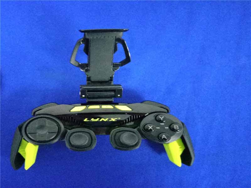
Aug 31, 2015Mad Catz L.Y.N.X.3 Mobile Wireless Controller
Equipment Class
DSS - Part 15 Spread Spectrum Transmitter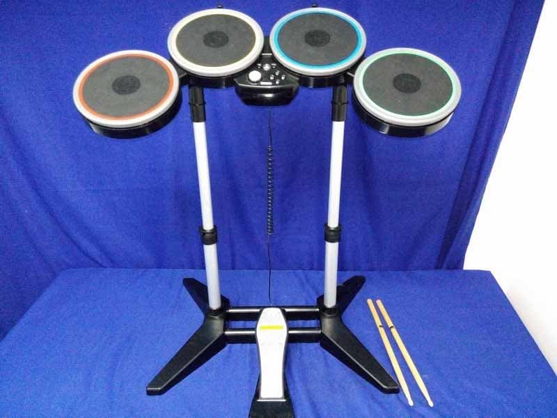
P25M991262A
Jun 24, 2015Rock Band 4 Wireless Drum Set for PlayStation 4
Equipment Class
DSS - Part 15 Spread Spectrum Transmitter
P25M991261A
Jun 02, 2015Rock Band 4 Wireless Fender Stratocasterfor PlayStation 4
Equipment Class
DSS - Part 15 Spread Spectrum Transmitter
P25SS32272A
Apr 25, 2015Mad Catz S.U.R.F.R
Equipment Class
DSS - Part 15 Spread Spectrum Transmitter
P25R232267A
Mar 03, 2015L.Y.N.X.9 Mobile Hybrid Controller
Equipment Class
DSS - Part 15 Spread Spectrum Transmitter