P25BWMC4556C1304CXOBX 2.4GHz RF CONTROLLER JOYPAD
Mad Catz, Inc.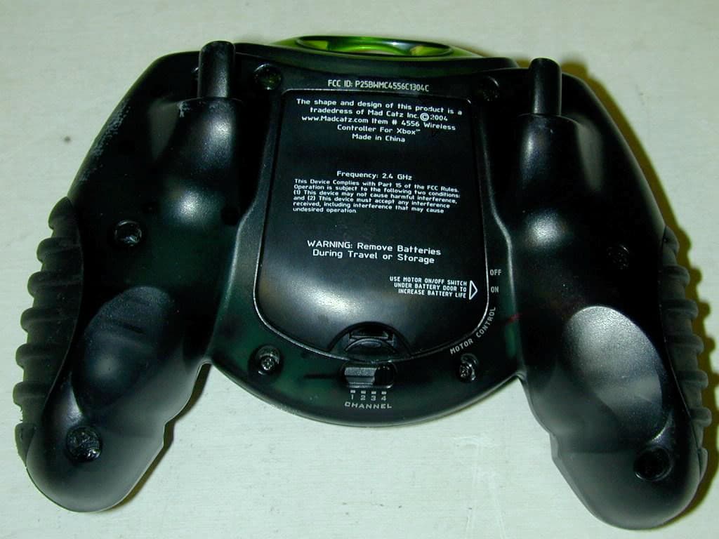
Click to zoom
Application Details
- Equipment Class
- DXX - Part 15 Low Power Communication Device Transmitter
- Date of Grant
- Feb 03, 2005
- Application Purpose
- Original Equipment
- Date of Application
- Feb 03, 2005
- Equipment Note
- XOBX 2.4GHz RF CONTROLLER JOYPAD
- Frequency Range
- 2401.00000000 - 2480.00000000
- Company
- Mad Catz, Inc.
- Country
- United States
Documents & Files
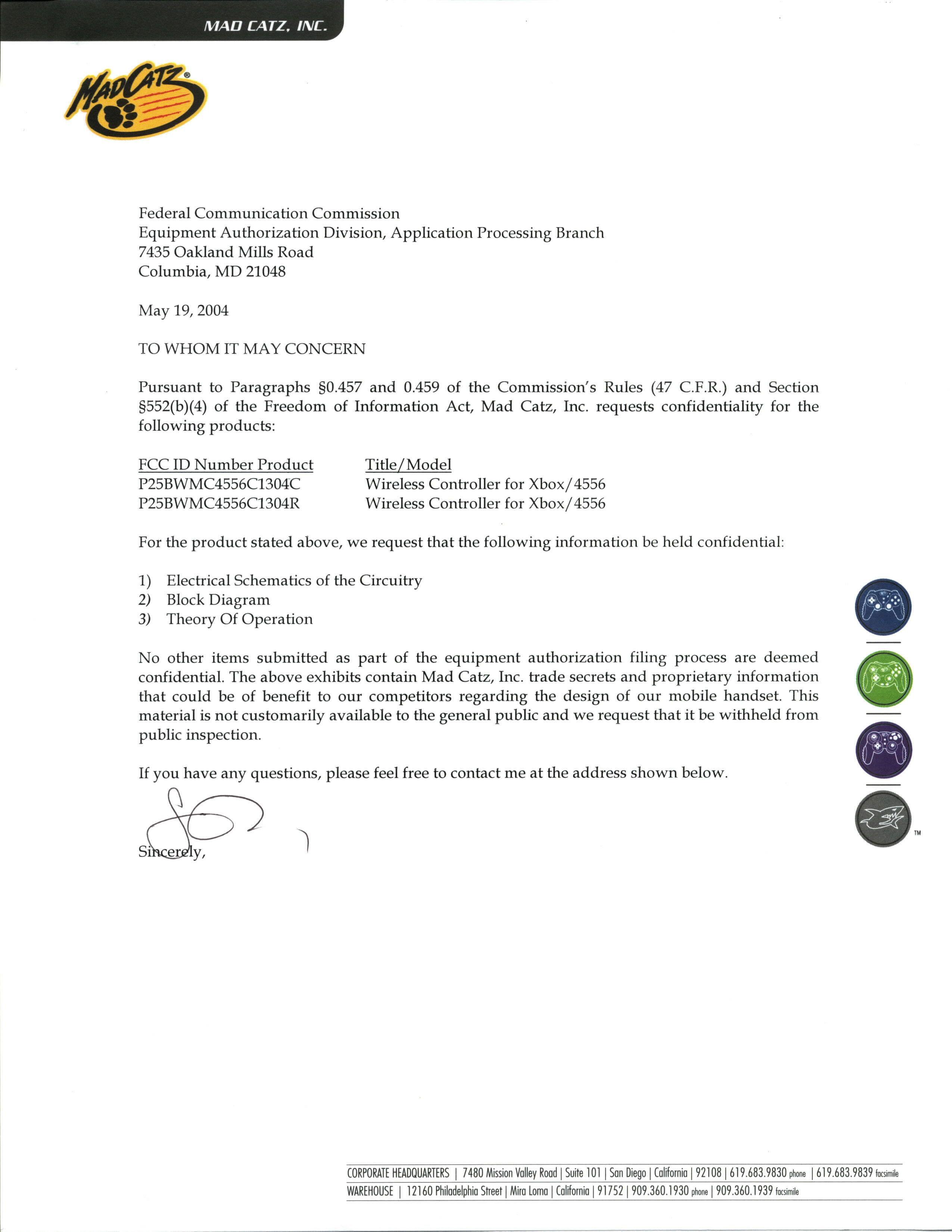
Document Text
Text extracted from the exhibit documents filed with the FCC. Open a document above to read the original.
Users Manual
ENGLISH LYNX ™ WIRELESS CONTROLLER XBOX ™ Thank you for purchasing the Mad Catz Lynx Wireless controller for use with the Xbox video game system. The Lynx puts you in control of your game system with all the comfort of a remote controller combined with the reliability of cutting-edge wireless technology. With its "unblockable" RF signal transceivers, the Lynx lets you comfortably play from up to 40’ from your Xbox while maintaining complete control over your gaming experience. This user guide will help you understand how to use your Lynx and get the most from the features it has to offer. The Lynx is one of the most durable and reliable accessories you can buy. Be sure to visit www.madcatz.com to register your product and check out our full line of other quality video game accessories. TABLE OF CONTENTS LAYOUT 1 POWER SAVE MODE 2 MULTIPLE CONTROLLERS 3 CAUTIONS 3 TROUBLESHOOTING 5 WARRANTY 5 TECHNICAL SUPPORT 6 LAYOUT Base Unit: Used to transmit and receive data from the controller to the game console. Houses two memory card expansion slots. Directional Pad: The D-pad controls the direction in which the character moves. Analog Sticks: The two analog sticks each control two axes (X-and Y-axis). Certain software titles will allow you to modify the way that the analog sticks are used and react in the games. Triggers Buttons (L and R): These are action buttons and their specific functions depend on the software being used. Action Buttons (A, B, X, Y, Black, White) : These buttons are used to perform various actions, depending on the software. For more details, see the software instruction manual. Start Button: This button is generally used to make selections in the menus and for pausing the game. For more details, see the software instruction manual. Back Button: This button is used to navigate backwards in the game menus. For more details, see the software instruction manual. Channel Selector: This is used for selecting a unique channel for each player's Lynx and Base Unit. Motor On/Off switch: This is used to turn the motor on or off to increase battery life. Low Battery Indicator: The Low Battery Indicator blinks when the battery level is low. Replace your batteries. Linkage Indicator: The Linkage Indicator at the receiver indicates whether the unit is connected (Lights on) or not connected (blinks). POWER SAVE MODE The Lynx controller has an automatic “Sleep” mode -- when the controller is not in use for about 10 minutes, the controller will partially turn itself off in order to conserve batteries. If Power Switch is on, wake the controller from sleep mode, 12 press D-Pad, analog sticks, BACK button or START button of the controller. MULTIPLE CONTROLLERS If you want to use two or more Lynx controllers at the same time (as in multi- player games), simply plug the controllers into the game system as you normally would and begin play. Confirm that each Lynx controller has a unique player number (1, 2, 3 or 4) and that it matches the player number selected on the Base Unit. When you play in the multi-player mode: 1. Insert the game disk and turn on your console. 2. Insert the Base Unit for the first controller into the Player-1 Controller port on the game console. 3. Confirm the link between first Base Unit and first Lynx by using the controller to see if it works in the game or game menu. 4. Insert the Base Unit for the second Lynx into the Player-2 Controller port on the game console. 5. Confirm the link between second Base Unit and second Lynx controller by using the controller to see if it works in the game or game menu. 6. IMPORTANT – Confirm that each Lynx controller has a unique player number (channel 1, 2, 3 or 4) and that it matches the player number selected on the Base Unit. CAUTIONS - Use this unit only as intended. - To prevent fire or shock hazard, do not expose this unit to rain or moisture. Do not use within 30’ of any water such as swimming pools, bathtubs, or sinks. - To avoid electrical shock, do not disassemble. Refer servicing to qualified personnel only. - Never push objects of any kind, other than authorized items, into the product as they may touch dangerous voltage points or short out parts that could result in fire or electrical shock. - Stop using this unit immediately if you begin to feel tired or if you experience discomfort or pain in your hands and/or arms while operating the unit. If the condition persists, consult a doctor. - Do not attempt to operate the unit in any way except with your hands. Do not bring the unit in contact with your head, face, or near the bones of any other part of your body. - The vibration function of this unit can aggravate injuries. Switch off or do not ENGLISH ENGLISH use the vibration function of the unit if you have any ailment of the bones or joints of your hands or arms. - Avoid prolonged use of this unit. Take breaks every 30 minutes. - Use this unit only as intended. - This product contains small parts that may cause choking if swallowed. Not intended for use by children under 3 years of age. Seizures Some indivduals may have seizures or black outs triggred by the flashing lights on television or in video games, even if they have never before had a seizure. Anyone who has had a seizure, loss of awareness, or other symptom linked to an epileptic condition should consult a doctor before playing a video game. Parents should be aware when their children play video games and observe them regularly. Stop playing and consult a doctor if you or your child have any of the following symptoms: Convulsions Loss of awareness Involuntary movements Eye or muscle twitching Altered vision Disorientation When playing video games: 1. Sit or stand as far from the screen as possible. 2. Play video games on the smallest available screen. 3. Do not play if you are tired or need rest. 4. Play in a well-lighted room. 5. Take a 15 minute break every hour. Repetitive Motion Injuries Playing video games (and the repeditive motion involved) can make your …
Text truncated - open the document above for the full version.
Block Diagram
Diagram 1. Host side 2. Controller side XBOX usb bus SPI Cypress Cy7c65113 6MHz Crystal NordIC nRF2401 16MHz Crystal PCB embedded antenna 5V -> 3.3V SONIX Sn8p1707 12MHz Crystal Buttons Joysticks NordIC nRF2401 16MHz Crystal SPI PCB embedded antenna 3.0V Regulator 3-AAA Size battery Motors
External Photos
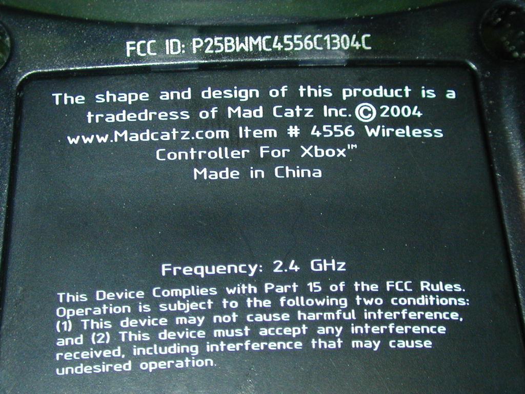
1 External Pictures 2
Operational Description
Wireless Joypad for Microsoft XBOX Theory of Operation 3/9/04 . 1. Station Side Radio The radio system is mainly composed of three parts: radio modem, frequency synthesizer and baseband microprocessor. The radio is interfaced with Microsoft XBOX via a 5-pin connector. Microsoft XBOX sends a command to the radio every 4 milliseconds. The radio takes the data from XBOX, packetize the data by adding preambles, frame information, and error checking bytes. The packetized frame is transmitted to the wireless joystick. When joystick replies, this radio receives the data, un-packetize it, and sends to Microsoft XBOX. The radio modem is a FSK modem running at 250 kbps with GFSK encoding to avoid frequency drifting. Frequency is controlled by a frequency synthesizer which adjusts a voltage-controlled RF oscillator dynamically for accurate frequency management. A total of 79 channels can be selected conversing the frequency range of 2.402 – 2.480GHz. The antenna is an embedded PCB antenna matching is done by using lumped inductors and capacitors. The radio is a half-duplex system and is powered by a 5V -> 3.3V regulator, power source provided by Microsoft XBOX. The total average power consumption of the radio system is about 25 mA at 3.3V. 2. Joypad Side Radio Joypad side radio operates in similar way to Station Side Radio as described in previous section. A total of 79 channels can be selected conversing the frequency range of 2.402 – 2.480GHz.. It scans keystrokes on the joypad. Similarly, the data is packetized in the same way as Station Side Radio. The joypad radio is powered by 3-AA side batteries and down regulated to 3.0V. Another provides power for two vibration motors in the joypad.
Schematics
123456 A B C D 654321 D C B A Title NumberRevisionSize B Date:10-Mar-2004Sheet of File:D:\XBOX24FCC.DDBDrawn By: VCC K2Right K3Up K4Left K1Down K16 Black RTr 50K LTr 50KK15 White K11 A K12 B K13 Y K14 X R401 15K Q3 8550 VCC A - + Left Motor Q1 8050 Vbat1 R108 6.8 R109 1K D1 4148 C106 104 A - + Right Motor Q2 8050 R110 15 R111 1K D2 4148 C107 104 Vbat1 C104 103 VPP Y101 12M C102 22P C103 22P C L K C101 4.7uF R101 2.7K VCC CE D0 D1 D2 D3PGM O E VCC R11410K R11310K R11210K K8LTh K6Back K5Start K7RTh G N D 1 V I N 2 V O U T 3 U200 AIC1734-30CXA VCC P1 Battery C201 100uF C203 104 C202 47uF VCC C105 104 RST XBOX 2.4GHz RF Gamepad + Turbo 2.2 Qiulin R107 10K R106 10K R402 2.7K RY 50K RX 50K LY 50K LX 50K 1 VPP 2 P0.0/INT0 3 P0.1/INT1 4 P0.2/INT2 5 RST 6 P1.5 7 P1.4 8 P1.3 9 VDD 10 P1.2 11 P1.1 1 2 P 1 . 0 1 3 P 2 . 0 1 4 P 2 . 1 1 5 P 2 . 2 1 6 P 2 . 3 1 7 V S S 1 8 A V S S 1 9 P 4 . 7 / A I N 7 2 0 P 4 . 6 / A I N 6 2 1 P 4 . 5 / A I N 5 2 2 P 4 . 4 / A I N 4 23 P4.3/AIN3 24 P4.2/AIN2 25 P4.1/AIN1 26 P4.0/AIN0 27 AVREF 28 VDD/AVDD 29 DAO 30 P5.7 31 P5.6 32 P5.5 33 P5.4/TC0/PWM0 3 4 P 5 . 3 / T C 1 / P W M 1 3 5 P 5 . 2 / S O 3 6 P 5 . 1 / S I 3 7 P 5 . 0 / S C K 3 8 P 2 . 4 3 9 P 2 . 5 4 0 P 2 . 6 4 1 P 2 . 7 4 2 V S S 4 3 X O U T 4 4 X I N U100 IC1 VCC D 4 D 5 D 6 D 7 Vbat DATA 2 CLK1 3 DR1 4 CS 5 DOUT2 6 CLK2 7 DR2 8 CE 9 PWR_UP 10 VDD 11 GND 12 GND 1 J1 NRF2401_PORT VCC 籵厘RF Module苤啣 LEFT_MOTOR LEFT_MOTOR Q201 S8550 R201 3.9K R202 20K R203 39K Q202 S8050 R204 100K R205 2.7K PWR_UP Low Voltage Detect PWR_UP R103 1K LED1 VCC RST VCC_O VCC_O 1234 8765 S501 Channel selector SER 10 P0 11 P1 12 P2 13 P3 14 P4 3 P5 4 P6 5 P7 6 CLK1 2 CLK2 15 PL 1 Q7 9 Q7 7 V C C 1 6 G N D 8 U500 74HC165 VCC KS_CSB KS_LDB C501 104P R506 100K R507 100K R508 100K R509 100K P W R _ U P D I P 0 D I P 1 D I P 2 D I P 3 DIP0 DIP1 DIP2 DIP3 K10Clear R501 10K R502 10K R503 10K R504 10K R505 10K VCC KS_CLK KS_DATA KS_DATA KS_LDB KS_CLK KS_CSB S3 Vdat
Test Setup Photos
1 Test Setup Pictures 2 3
Contact Information
Applicant
Parco Liu(Quality Manager)
Test Firm
ATLAS Compliance & Engineering, Inc.Bruce Smith
Technical Specifications
| # | Rule Parts | Frequency Range | Power Output |
|---|---|---|---|
| 1 | 15C | 2.40 GHz - 2.48 GHz | - |
Other Applications from Mad Catz, Inc.
P25SS32269A
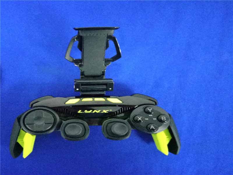
Aug 31, 2015Mad Catz L.Y.N.X.3 Mobile Wireless Controller
Equipment Class
DSS - Part 15 Spread Spectrum Transmitter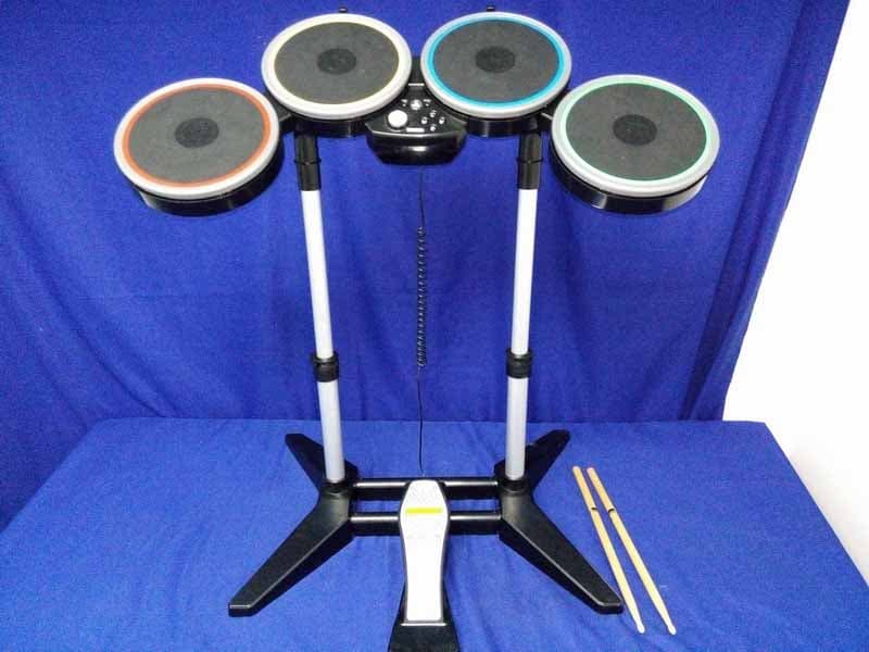
P25M991262A
Jun 24, 2015Rock Band 4 Wireless Drum Set for PlayStation 4
Equipment Class
DSS - Part 15 Spread Spectrum Transmitter
P25M991261A
Jun 02, 2015Rock Band 4 Wireless Fender Stratocasterfor PlayStation 4
Equipment Class
DSS - Part 15 Spread Spectrum Transmitter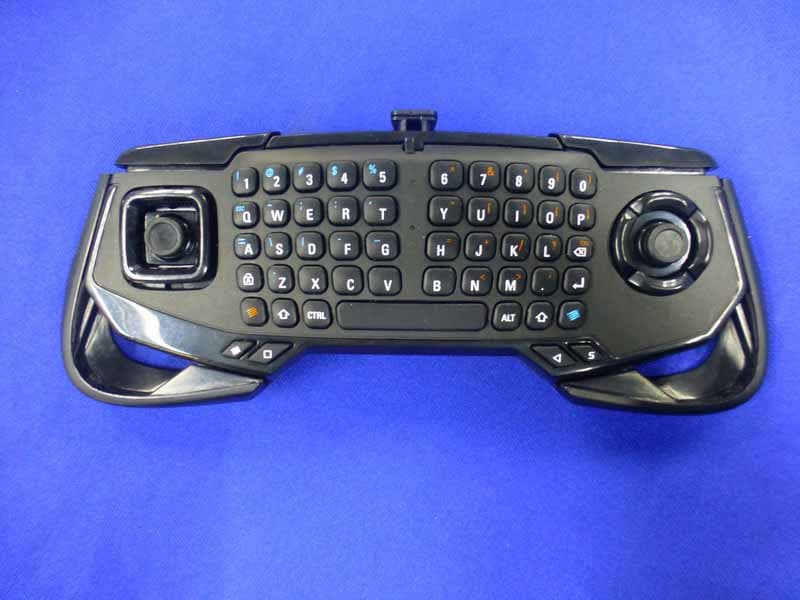
P25SS32272A
Apr 25, 2015Mad Catz S.U.R.F.R
Equipment Class
DSS - Part 15 Spread Spectrum Transmitter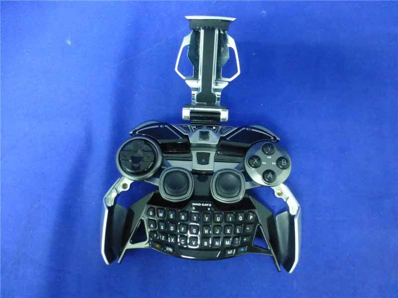
P25R232267A
Mar 03, 2015L.Y.N.X.9 Mobile Hybrid Controller
Equipment Class
DSS - Part 15 Spread Spectrum Transmitter