P25D232268A4813CMad Catz Micro C.T.R.L.R
Mad Catz, Inc.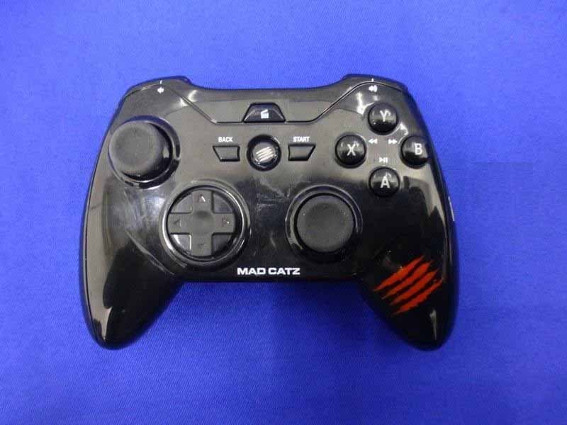
Click to zoom
Application Details
- Equipment Class
- DTS - Digital Transmission System
- Date of Grant
- Mar 24, 2014
- Application Purpose
- Original Equipment
- Date of Application
- Mar 24, 2014
- Equipment Note
- Mad Catz Micro C.T.R.L.R
- Frequency Range
- 2402.00000000 - 2480.00000000
- Company
- Mad Catz, Inc.
- Country
- United States
Documents & Files
Document Text
Text extracted from the exhibit documents filed with the FCC. Open a document above to read the original.
Users Manual
M Set Ve 1. I 2 x A hand Set u Set u Me d To ac labe Rele LED Blink Solid Solid Purp Imp o Pow Clea Ga m The g here Ga m Mo u click PC M com ad Ca tup Instr rsion 1. 0 Installati AAA batteries dles. up with Dongl 1. Ensure b 2. Insert U S 3. Press and 4. Wait for 5. When th up without Do 1. Ensure b 2. Make su r 3. Press and 4. Press and 5. Search fo dia Functions ccess the med lled button on ase the media Indicators king Red to Bl d Blue: Conne d Red: Low Ba ple Flash: Pair ortant Button er product on r pairing infor me Pad Modes gamepad has e are our sugg meSmart Mod use Mode: Thi s. Select this m Mode: Select t patibility with atz OEM uctions 0 ion are required t e atteries are i n SB dongle into d hold the hom the pad to au e Home LED i ongle – This is atteries are i n re the USB do d hold the hom d hold the Sta or devices on t dia control pre n the pad. a shift button ue: Discover a cted ttery ing info is re m n Presses n/off: Press an rmation and e s three modes estions: e: Select this is mode enab mode on eithe this mode PC g h games that d M Gam to power the nserted. o an available me button for utomatically co s lit constantl only compat i nserted. ongle is not plu me button for art button for the host, whe ess and hold t to continue u able moved nd hold the ho enter pairing m . Each mode i mode for An d les the left sti er Android or gaming on Wi do not suppor mepad product. 1 ba USB port. r 3 seconds to onnect. y blue, the p a ible with Wind ugged in. r 3 seconds to 5 seconds to en the gamepa the media shif using the pad ome button fo mode: Press a s slightly diff e droid gaming o ick to control PC to naviga t indows. In thi rt pads. d attery is insert o power the p ad is ready to dows 8 and An o power the p enter pairing ad appears, ta ft button (abo normally. or 3 seconds nd hold Start erence in term on M.O.J.O., s the mouse cu te menus, ent s mode, the p ted into the b ad on. use. ndroid 4.4 dev ad on. mode. ap the entry t ove the home button for 5 s ms of function smartphones a ursor. The face ter text, brow pad can also b attery compa vices that supp o pair and con button) and p seconds. ality.If you ar and tablets. e and bumper se apps or pla be programme rtment in bot port Bluetoot nnect. press the corr e unsure abou r buttons will ay touch input ed with profile th left and righ h Smart devic responding ut which to us control mous t games. es to enable 1 ht ces. se, e 2 FCC Statement Changes or modifications not expressly approved by the party responsible for compliance could void the user's authority to operate the equipment This device complies with Part 15 of the FCC Rules. Operation is subject to the following two conditions: (1) this device may not cause harmful interference, and (2) this device must accept any interference received, including interference that may cause undesired operation. IC Statement This device complies with Industry Canada licence‐exempt RSS standard(s). Operation is subject to the following two conditions: (1) this device may not cause interference, and (2) this device must accept any interference, including interference that may cause undesired operation of the device. Le présent appareil est conforme aux CNR d'Industrie Canada applicables aux appareils radio exempts de licence. L'exploitation est autorisée aux deux conditions suivantes : (1) l'appareil ne doit pas produire de brouillage, et (2) l'utilisateur de l'appareil doit accepter tout brouillage radioélectrique subi, même si le brouillage est susceptible d'en compromettre le fonctionnement. 3
External Photos
R AUDIX Technology (Shenzhen) Co., Ltd. FCC ID:P25D232268A4813C page Audix Technology (Shenzhen) Co., Ltd. Report No. ACS-F14052 12-1 12. PHOTOGRAPH OF EUT Figure 1 General Appearance of the EUT Figure 2 General Appearance of the EUT R AUDIX Technology (Shenzhen) Co., Ltd. FCC ID:P25D232268A4813C page Audix Technology (Shenzhen) Co., Ltd. Report No. ACS-F14052 12-2 Figure 3 General Appearance of the EUT Figure 4 General Appearance of the EUT R AUDIX Technology (Shenzhen) Co., Ltd. FCC ID:P25D232268A4813C page Audix Technology (Shenzhen) Co., Ltd. Report No. ACS-F14052 12-3 Figure 5 General Appearance of the EUT Figure 6 General Appearance of the EUT R AUDIX Technology (Shenzhen) Co., Ltd. FCC ID:P25D232268A4813C page Audix Technology (Shenzhen) Co., Ltd. Report No. ACS-F14052 12-4 Figure 6 General Appearance of the EUT Figure 7 Inside of the EUT
Internal Photos
R AUDIX Technology (Shenzhen) Co., Ltd. FCC ID:P25D232268A4813C page Audix Technology (Shenzhen) Co., Ltd. Report No. ACS-F14052 12-5 Figure 8 Inside of the EUT Figure 8 Inside of the EUT R AUDIX Technology (Shenzhen) Co., Ltd. FCC ID:P25D232268A4813C page Audix Technology (Shenzhen) Co., Ltd. Report No. ACS-F14052 12-6 Figure 12 Components Side of the PCB Figure 13 Components Side of the PCB R AUDIX Technology (Shenzhen) Co., Ltd. FCC ID:P25D232268A4813C page Audix Technology (Shenzhen) Co., Ltd. Report No. ACS-F14052 12-7 Figure 14 Components Side of the PCB Figure 15 Components Side of the PCB R AUDIX Technology (Shenzhen) Co., Ltd. FCC ID:P25D232268A4813C page Audix Technology (Shenzhen) Co., Ltd. Report No. ACS-F14052 12-8 Figure16 Components Side of the PCB Figure 17 Components Side of the PCB R AUDIX Technology (Shenzhen) Co., Ltd. FCC ID:P25D232268A4813C page Audix Technology (Shenzhen) Co., Ltd. Report No. ACS-F14052 12-9 Figure 18 Components Side of the PCB
RF Exposure Info
RF Exposure evaluation According to 447498 D01 General RF Exposure Guidance v05 The 1-g and 10-g SAR test exclusion thresholds for 100 MHz to 6 GHz at test separation distances ≤ 50 mm are determined by: [(max. power of channel, including tune-up tolerance, mW)/(min. test separation distance, mm)] ·[√f(GHz)] ≤ 3.0 for 1-g SAR and ≤ 7.5 for 10-g extremity SAR, where f(GHz) is the RF channel transmit frequency in GHz Power and distance are rounded to the nearest mW and mm before calculation The result is rounded to one decimal place for comparison Worse case is as below: [2480MHz -0.290dBm(0.935mW) output power] (0.935mW /5mm) ·[√2.48 (GHz)]= 0.294 <3.0 for 1-g SAR Then SAR evaluation is not required
Test Report
R AUDIX Technology (Shenzhen) Co., Ltd. FCC ID:P25D232268A4813C Audix Technology (Shenzhen) Co., Ltd. Report No. ACS-F14052 FCC PART 15C TEST REPORT FOR CERTIFICATION On Behalf of Mad Catz Inc. Mad Catz Micro C.T.R.L.R Model No. : 32268 FCC ID: P25D232268A4813C Prepared for : Mad Catz Inc. 7480 Mission Valley Road, Suite 101, San Diego, California, 92108, USA Prepared By : Audix Technology (Shenzhen) Co., Ltd. No. 6, Ke Feng Rd., 52 Block, Shenzhen Science & Industrial Park, Nantou, Shenzhen, Guangdong, China Tel: (0755) 26639496 Report Number : ACS-F14052 Date of Test : Dec.26, 2013~Jan.22, 2014 Date of Report : Mar.21, 2014 R AUDIX Technology (Shenzhen) Co., Ltd. FCC ID:P25D232268A4813C Audix Technology (Shenzhen) Co., Ltd. Report No. ACS-F14052 TABLE OF CONTENTS Description Page 1. SUMMARY OF STANDARDS AND RESULTS ......................................................... 1-1 1.1. Description of Standards and Results .................................................................................. 1-1 2. GENERAL INFORMATION ......................................................................................... 2-1 2.1. Description of Device (EUT) ............................................................................................... 2-1 2.2. Block Diagram of connection between EUT and simulators ............................................... 2-2 2.3. Test information ................................................................................................................... 2-2 2.4. Test Facility.......................................................................................................................... 2-3 2.5. Measurement Uncertainty (95% confidence levels, k=2) .................................................... 2-3 3. POWER LINE CONDUCTED EMISSION MEASUREMENT ................................. 3-1 4. RADIATED EMISSION MEASUREMENT ................................................................ 4-1 4.1. Test Equipment .................................................................................................................... 4-1 4.2. Block Diagram of Test Setup ............................................................................................... 4-2 4.3. Radiated Emission Limit Standard: FCC 15.209 ................................................................. 4-3 4.4. EUT Configuration on Test.................................................................................................. 4-3 4.5. Operating Condition of EUT................................................................................................ 4-3 4.6. Test Procedure...................................................................................................................... 4-3 4.7. Radiated Emission Test Results ........................................................................................... 4-4 5. CONDUCTED SPURIOUS EMISSIONS ..................................................................... 5-1 5.1. Test Equipment .................................................................................................................... 5-1 5.2. Limit..................................................................................................................................... 5-1 5.3. Test Procedure...................................................................................................................... 5-1 5.4. Test result ............................................................................................................................. 5-1 6. 6dB BANDWIDTH TEST ............................................................................................... 6-1 6.1. Test Equipment .................................................................................................................... 6-1 6.2. Limit..................................................................................................................................... 6-1 6.3. Test Procedure...................................................................................................................... 6-1 6.4. Test Results .......................................................................................................................... 6-1 7. MAXIMUM PEAK OUTPUT POWER TEST ............................................................. 7-1 7.1. Test Equipment .................................................................................................................... 7-1 7.2. Limit..................................................................................................................................... 7-1 7.3. Test Procedure...................................................................................................................... 7-1 7.4. Test Results .......................................................................................................................... 7-1 8. BAND EDGE COMPLIANCE TEST ............................................................................ 8-1 8.1. Test Equipment .................................................................................................................... 8-1 8.2. Limit..................................................................................................................................... 8-1 8.3. Test Produce ......................................................................................................................... 8-1 8.4. Test Results .......................................................................................................................... 8-1 9. POWER SPECTRAL DENSITY TEST ........................................................................ 9-1 9.1. Test Equipment .................................................................................................................... 9-1 9.2. Limit.............................................................................................…
Text truncated - open the document above for the full version.
Test Setup Photos
R AUDIX Technology (Shenzhen) Co., Ltd. FCC ID:P25D232268A4813C page Audix Technology (Shenzhen) Co., Ltd. Report No. ACS-F14052 11-1 11. HOTOGRAPH OF TEST 11.1.Photos of Radiated Emission Test 30-1000MHz R AUDIX Technology (Shenzhen) Co., Ltd. FCC ID:P25D232268A4813C page Audix Technology (Shenzhen) Co., Ltd. Report No. ACS-F14052 11-2 Above 1000MHz
Contact Information
Applicant
Parco Liu(Quality Manager)
Test Firm
Audix Technology (Shenzhen) Co.Smart Tsai
Technical Specifications
| # | Rule Parts | Frequency Range | Power Output |
|---|---|---|---|
| 1 | 15C | 2.40 GHz - 2.48 GHz | 935.00 µW |
Other Applications from Mad Catz, Inc.
P25SS32269A
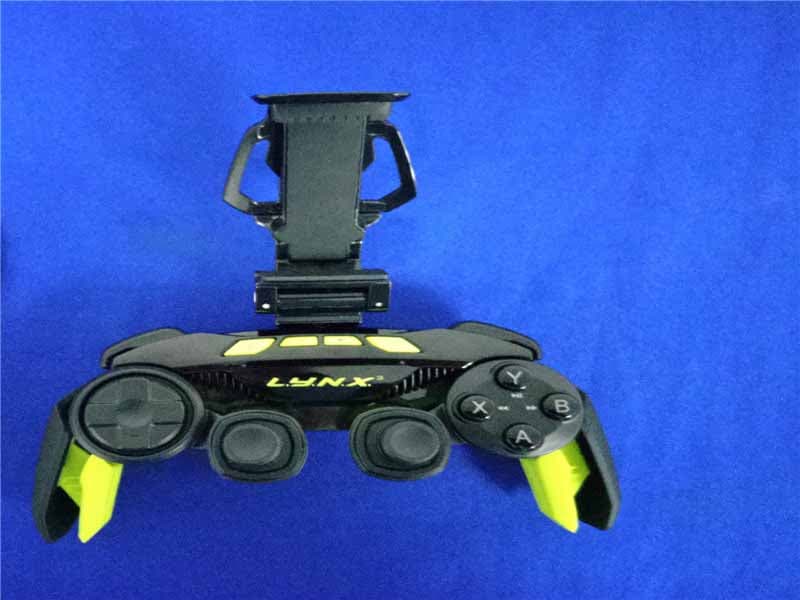
Aug 31, 2015Mad Catz L.Y.N.X.3 Mobile Wireless Controller
Equipment Class
DSS - Part 15 Spread Spectrum Transmitter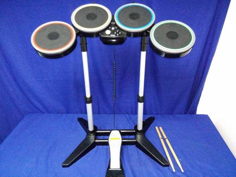
P25M991262A
Jun 24, 2015Rock Band 4 Wireless Drum Set for PlayStation 4
Equipment Class
DSS - Part 15 Spread Spectrum Transmitter
P25M991261A
Jun 02, 2015Rock Band 4 Wireless Fender Stratocasterfor PlayStation 4
Equipment Class
DSS - Part 15 Spread Spectrum Transmitter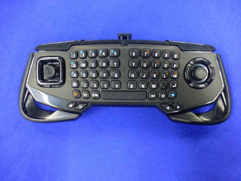
P25SS32272A
Apr 25, 2015Mad Catz S.U.R.F.R
Equipment Class
DSS - Part 15 Spread Spectrum Transmitter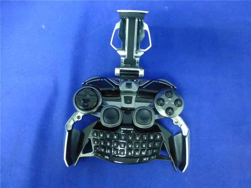
P25R232267A
Mar 03, 2015L.Y.N.X.9 Mobile Hybrid Controller
Equipment Class
DSS - Part 15 Spread Spectrum Transmitter