P25G088391S1014RCyborg Wireless Stick (Dongle)
Mad Catz, Inc.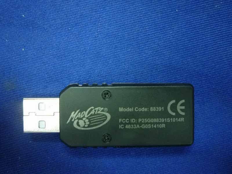
Click to zoom
Application Details
- Equipment Class
- DXX - Part 15 Low Power Communication Device Transmitter
- Date of Grant
- Sep 08, 2010
- Application Purpose
- Original Equipment
- Date of Application
- Sep 07, 2010
- Equipment Note
- Cyborg Wireless Stick (Dongle)
- Frequency Range
- 2408.00000000 - 2476.00000000
- Company
- Mad Catz, Inc.
- Country
- United States
Documents & Files
Document Text
Text extracted from the exhibit documents filed with the FCC. Open a document above to read the original.
Users Manual
88931_MUG.indd 188931_MUG.indd 110-8-3 2:0410-8-3 2:04 [2][3] ENGLISH Cyborg F.L.Y. 9 Wireless Flight Stick Thank you for purchasing the Cyborg F.L.Y. 9 Wireless Flight Stick for use with the PlayStation 3 video game system. Be sure to register your product online at www.madcatz.com and check out our full line of other quality video game accessories. IMPORTANT! Before using the PlayStation 3 system with this product, read the PlayStation 3 system instruction manual for safety, health, and other information regarding the use of the PlayStation 3 system. All questions regarding the console should be directed to the manufacturer. GENERAL SETUP CONNECTING YOUR CONTROLLER TO YOUR PS3 SYSTEM Up to four controllers, wired and wireless, can be actively connected to a PlayStation 3 console at one time. Each connected controller is assigned a player indicator number. To connect a wireless controller, a player indicator number must be free (unlit). 1. Insert 2 (two) AA batteries into the battery compartment. 2. Insert the USB receiver into any available USB port on the PS3 – the receiver’s Red LED will fl ash. 3. Power ON the Wireless Flight Stick – the 4 (four) controller port indicator LEDs located at the top of the Flight Stick will rapidly fl ash while the Flight Stick is searching for a signal. 4. Once a connection has been established, the 4 (four) LEDs will fl ash less rapidly and the receiver’s LED will turn solid. 5. Press the PS Button (located between Start and Select) on the Flight Stick. The PS3 will automatically assign a player number – from 1 (one) to 7 (seven). 6. The assigned player number will be indicated by the LEDs at the top of the Flight Stick: a. Player 1 (one) – the LED above the # 1 (one) position will be lit. b. Player 6 (six) – the LEDs above the # 2 (two) and # 4 (four) positions will be lit. Refer to your PS3’s instruction manual for more information. SETTING UP YOUR WIRELESS FLIGHT STICK A. Attach the Flight Stick handle to the base by inserting it into the base collar and tightening the securing screw. B. Remove the adjustment tool from the compartment on the Flight Stick base. C. Press the locking switch (c1) and move the Flight Stick up or down to adjust the height. D. Insert the adjustment tool in the locking nut (d2) and turn counter-clockwise. Press the locking pin (d1) in and move the stick forward or backwards to the required angle. Lock by turning locking nut (d2) clockwise. E. Insert the adjustment tool into the locking nut (e1) and turn counter-clockwise. Move to the desired angle and lock by turning the locking nut clockwise. LAP-MOUNT OPTIONS To m a k e i t e a s i e r t o u s e y o u r F l i g h t S t i c k o n y o u r l a p , w e h a v e a d d e d 4 ( f o u r ) l a p - m o u n t b r a c k e t s . To a t t a c h t h e b r a c k e t s , t u r n the Flight Stick over. Each bracket will display the letter L or R. The L brackets will attach onto the left side and the R brackets will attach onto the right side. To attach, push the brackets into the securing holes (f1) and with all brackets in place, slide the lock catches (f2) into place. CONFIGURING YOUR WIRELESS FLIGHT STICK FOR DIFFERENT GAME TITLES Yo u r F l i g h t S t i c k h a s t w o m o d e s w h i c h c o n fi g u r e c o n t r o l s f o r s p e c i fi c fl y i n g g a m e s . Yo u c a n s w i t c h b e t w e e n m o d e s b y s l i d i n g t h e switch on the right side of the Flight Stick base to either mode M1 or M2. In mode M1, all controls will have the default labeled function - please see your game manual. Mode M1 (Page 4) - Your Flight Stick buttons and controls are confi gured to play IL-2 Sturmovik, Tom Clancy: HAWX, or any future fl ight simulation games. Mode M2 (Page 5) - Your Flight Stick buttons and controls are confi gured to play Blazing Angels 1 and 2. FREQUENTLY ASKED QUESTIONS (FAQ) QUESTION: When I have the Cyborg F.L.Y. 9 Flight Stick plugged into my PS3, I cannot navigate the XMB (XrossMediaBar) menu correctly. ANSWER: Ensure the throttle is set to the “0” (neutral) position. If the throttle is engaged all the way up or down, you may experience the XMB menu moving unexpectedly. When the Flight Stick is in mode 2, the throttle emulates the analog stick on a standard gaming controller used to navigate the XMB menu. QUESTION: My Flight Stick is not functioning at all. The LEDs surrounding the PS button are fl ashing, but there is no response in the XMB menu or game. ANSWER 1 : Ensure fresh batteries are in the Flight Stick. If the battery level is too low, you may experience loss of connection to the USB dongle and console. ANSWER 2: Pair again (synchronize) the USB dongle with the Flight Stick: 1. Insert USB dongle into PS3 console. 2. Power ON Flight Stick by pushing PS button. 3. Simultaneously hold down both the PS button and the L3 (left stick button) for 5-10 seconds. 4. If successfully paired, the player indicator LEDs surrounding the PS button will no longer fl ash, and one of those LEDs will stay lit. ABCDE c1 d1 d2 e1 F f1 f2 88931_MUG.indd 2-388931_MUG.indd 2-310-8-3 2:0410-8-3 2:04 [4][5] ! Button Bouton ! Botón ! ! Taste Pulsante ! !-knap !-knapp Botão ! L1 Button Bouton L1 Botón L1 L1 Taste Pulsante L1 L1-knap L1-knapp Botão L1 Right Stick Stick Droit Derecho Stick Rechter Stick Levetta Sestra Højre Stick Rätt Stick Direito Stick Head Mini Stick D-Pad Mini Stick de Tête D-Pad D-Pad en la cabeza del stick Kopf Mini Stick - D-Pad Mini Stick D-Pad principale Primær Mini Stick D-Pad Huvudministyrspak D-Pad mini-manípulo principal " Button Bouton " Botón " " Taste Pulsante " "-knap "-knapp Botão " R2 Button Bouton R2 Botón R2 R2 Taste Pulsante R2 R2-knap R2-knapp Botão R2 Left Mini Stick Button Mini Stick Bouton de Gauche Stick de izquierdo de boton Linker Mini Stick Taste Pulsante sinistro del mini stick Venstre Mini Stick-knap Vänster minispaksknapp Botão mini-manípulo esquerdo ! Button Bouton ! Botón ! ! Taste Pulsante ! !-knap !-knapp Botão ! Right Mini Stick Butto…
Text truncated - open the document above for the full version.
External Photos
FCC ID:P25G088391S1014R page Audix Technology (Shenzhen) Co., Ltd. Report No. ACS-F10156 9-1 9. PHOTOGRAPH OF EUT Figure 1 General Appearance of the EUT Figure 2 General Appearance of the EUT
ID Label/Location Info
Label Location
Internal Photos
FCC ID:P25G088391S1014R page Audix Technology (Shenzhen) Co., Ltd. Report No. ACS-F10156 9-2 Figure 3 Inside of the EUT Figure 4 Inside of the EUT FCC ID:P25G088391S1014R page Audix Technology (Shenzhen) Co., Ltd. Report No. ACS-F10156 9-3 Figure 5 Inside of the EUT
Test Report
FCC ID:P25G088391S1014R Audix Technology (Shenzhen) Co., Ltd. Report No. ACS-F10156 APPLICATION FOR CERTIFICATION On Behalf of Mad Catz, Inc. Cyborg Wireless Stick (Dongle) Model Number: 88391 FCC ID: P25G088391S1014R Prepared for : Mad Catz, Inc. 7480 Mission Valley Road, Suite 101, San Diego, California, 92108, USA Prepared By : Audix Technology (Shenzhen) Co., Ltd. No. 6, Ke Feng Rd., 52 Block, Shenzhen Science & Industrial Park, Nantou, Shenzhen, Guangdong, China Tel: (0755) 26639496 Report Number : ACS-F10156 Date of Test : Apr.23~Jul.07, 2010 Date of Report : Jul.08, 2010 FCC ID:P25G088391S1014R Audix Technology (Shenzhen) Co., Ltd. Report No. ACS-F10156 TABLE OF CONTENTS Description Page 1. SUMMARY OF STANDARDS AND RESULTS .................................................................. 1-1 1.1. Description of Standards and Results.............................................................................................1-1 2. GENERAL INFORMATION .................................................................................................. 2-1 2.1. Description of Device (EUT) .........................................................................................................2-1 2.2. Tested Supporting System Details .................................................................................................2-1 2.3. Test Facility....................................................................................................................................2-2 2.4. Test Uncertainty (95% confidence levels, k=2) .............................................................................2-2 3. POWER LINE CONDUCTED EMISSION TEST................................................................ 3-1 3.1. Test Equipments.............................................................................................................................3-1 3.2. Block Diagram of Test Setup .........................................................................................................3-1 3.3. Power Line Conducted Emission Test Limits ................................................................................3-1 3.4. Configuration of EUT on Test .......................................................................................................3-2 3.5. Operating Condition of EUT..........................................................................................................3-2 3.6. Test Procedure................................................................................................................................3-2 3.7. Power Line Conducted Emission Test Results...............................................................................3-2 4. RADIATED EMISSION TEST ............................................................................................... 4-1 4.1. Test Equipment ..............................................................................................................................4-1 4.2. Block Diagram of Test Setup .........................................................................................................4-1 4.3. Radiated Emission Limit Standard: FCC 15.209 and 15.249 ........................................................4-2 4.4. EUT Configuration on Test............................................................................................................4-3 4.5. Operating Condition of EUT..........................................................................................................4-3 4.6. Test Procedure................................................................................................................................4-3 4.7. Radiated Emission Test Results .....................................................................................................4-3 5. BAND EDGE COMPLIANCE TEST ..................................................................................... 5-1 5.1. Test Equipment ..............................................................................................................................5-1 5.2. Limit ...............................................................................................................................................5-1 5.3. Test Produce ...................................................................................................................................5-1 5.4. Test Results ....................................................................................................................................5-1 6. 20DB BANDWIDTH TEST ..................................................................................................... 6-1 6.1. Test Equipment ..............................................................................................................................6-1 6.2. Limit ...............................................................................................................................................6-1 6.3. Test Results ....................................................................................................................................6-1 7. DEVIATION TO TEST SPECIFICATIONS ........................................................................ 7-1 8. PHOTOGRAPH OF TEST...................................................................................................... 8-1 8.1. Photos of Power Line Conducted Emission Test ...........................................................................8-1 8.2. Photos of Radiated Emission Test (In Anechoic Chamber) ...........................................................8-2 9. PHOTOGRAPH OF EUT........................................................................................................ 9-1 FCC ID:P25G088391S1014R Page Audix Technology (Shenzhen) Co., Ltd. Report No. ACS-F10156 1-1 1. SUMMARY OF STANDARDS AND RESULTS 1.1. Description of Standards and Results The EUT have been tested according …
Text truncated - open the document above for the full version.
Test Setup Photos
FCC ID:P25G088391S1014R page Audix Technology (Shenzhen) Co., Ltd. Report No. ACS-F10156 8-1 8. PHOTOGRAPH OF TEST 8.1. Photos of Power Line Conducted Emission Test FCC ID:P25G088391S1014R page Audix Technology (Shenzhen) Co., Ltd. Report No. ACS-F10156 8-2 8.2. Photos of Radiated Emission Test (In Anechoic Chamber) 30~1000MHz FCC ID:P25G088391S1014R page Audix Technology (Shenzhen) Co., Ltd. Report No. ACS-F10156 8-3 Above 1000MHz
Contact Information
Applicant
Parco Liu(Quality Manager)
Technical Contact
AUDIX Technology (Shenzhen) Co., Ltd.
[email protected]86-755-26639497
52 Block Shenzhen Science&Industry · Shenzhen · China
Test Firm
Audix Technology (Shenzhen) Co., Ltd.Smart Tsai
Technical Specifications
| # | Rule Parts | Frequency Range | Power Output |
|---|---|---|---|
| 1 | 15C | 2.41 GHz - 2.48 GHz | - |
Other Applications from Mad Catz, Inc.
P25SS32269A
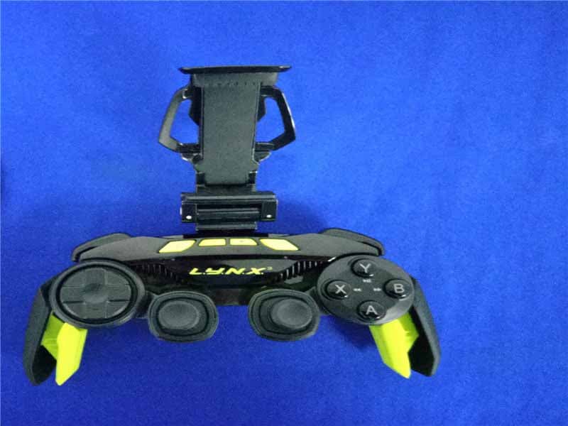
Aug 31, 2015Mad Catz L.Y.N.X.3 Mobile Wireless Controller
Equipment Class
DSS - Part 15 Spread Spectrum Transmitter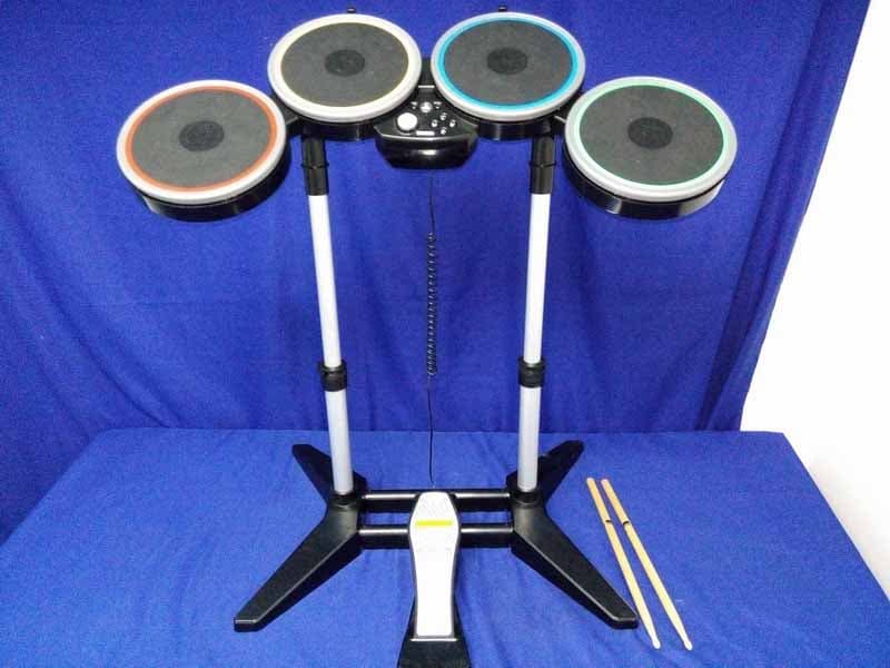
P25M991262A
Jun 24, 2015Rock Band 4 Wireless Drum Set for PlayStation 4
Equipment Class
DSS - Part 15 Spread Spectrum Transmitter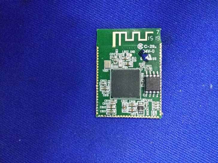
P25M991261A
Jun 02, 2015Rock Band 4 Wireless Fender Stratocasterfor PlayStation 4
Equipment Class
DSS - Part 15 Spread Spectrum Transmitter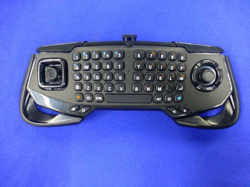
P25SS32272A
Apr 25, 2015Mad Catz S.U.R.F.R
Equipment Class
DSS - Part 15 Spread Spectrum Transmitter
P25R232267A
Mar 03, 2015L.Y.N.X.9 Mobile Hybrid Controller
Equipment Class
DSS - Part 15 Spread Spectrum Transmitter