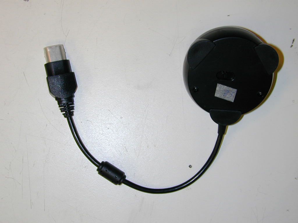
P25HEMC4556A4002RLynx Xbox Wireless Base
Mad Catz, Inc.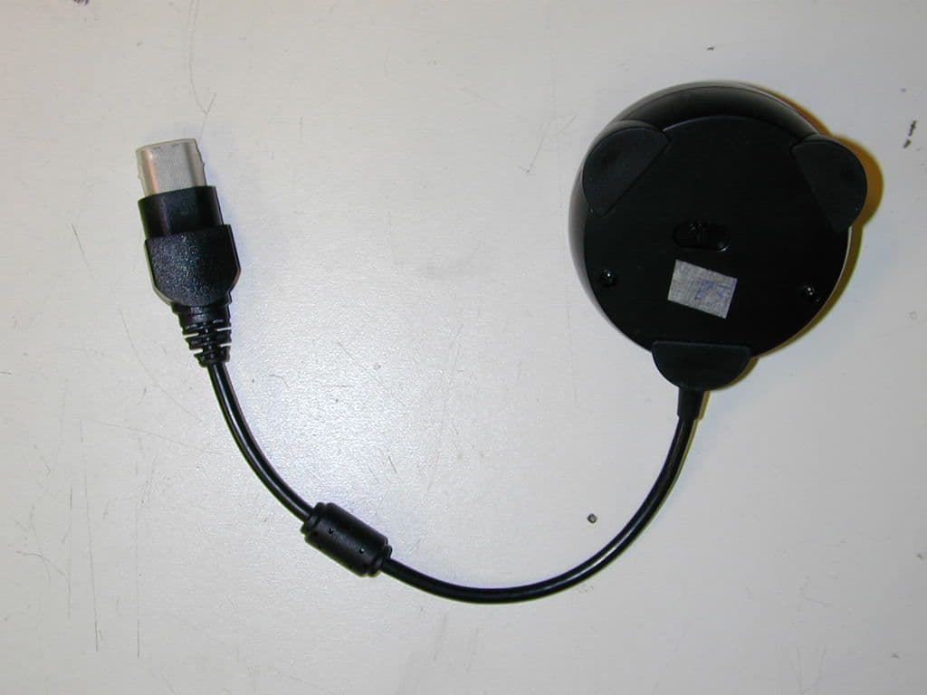
Click to zoom
Application Details
- Equipment Class
- DXT - Part 15 Low Power Transceiver, Rx Verified
- Date of Grant
- Nov 05, 2002
- Application Purpose
- Original Equipment
- Date of Application
- Nov 05, 2002
- Equipment Note
- Lynx Xbox Wireless Base
- Frequency Range
- 905.75000000 - 924.18000000
- Company
- Mad Catz, Inc.
- Country
- United States
Documents & Files
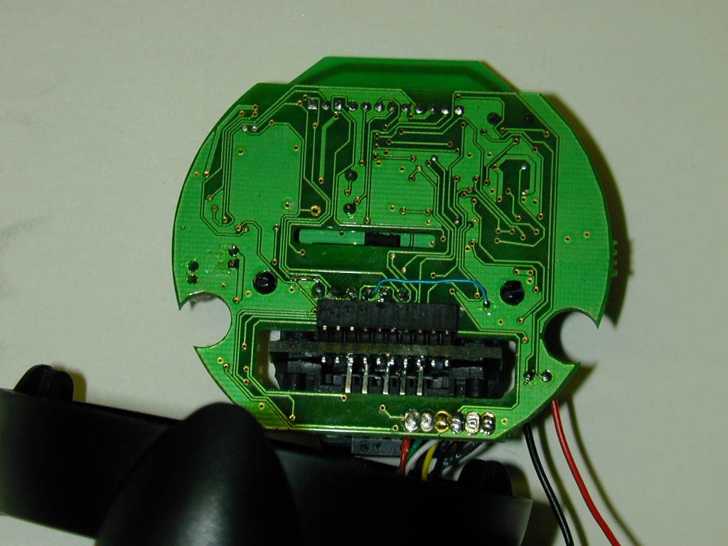
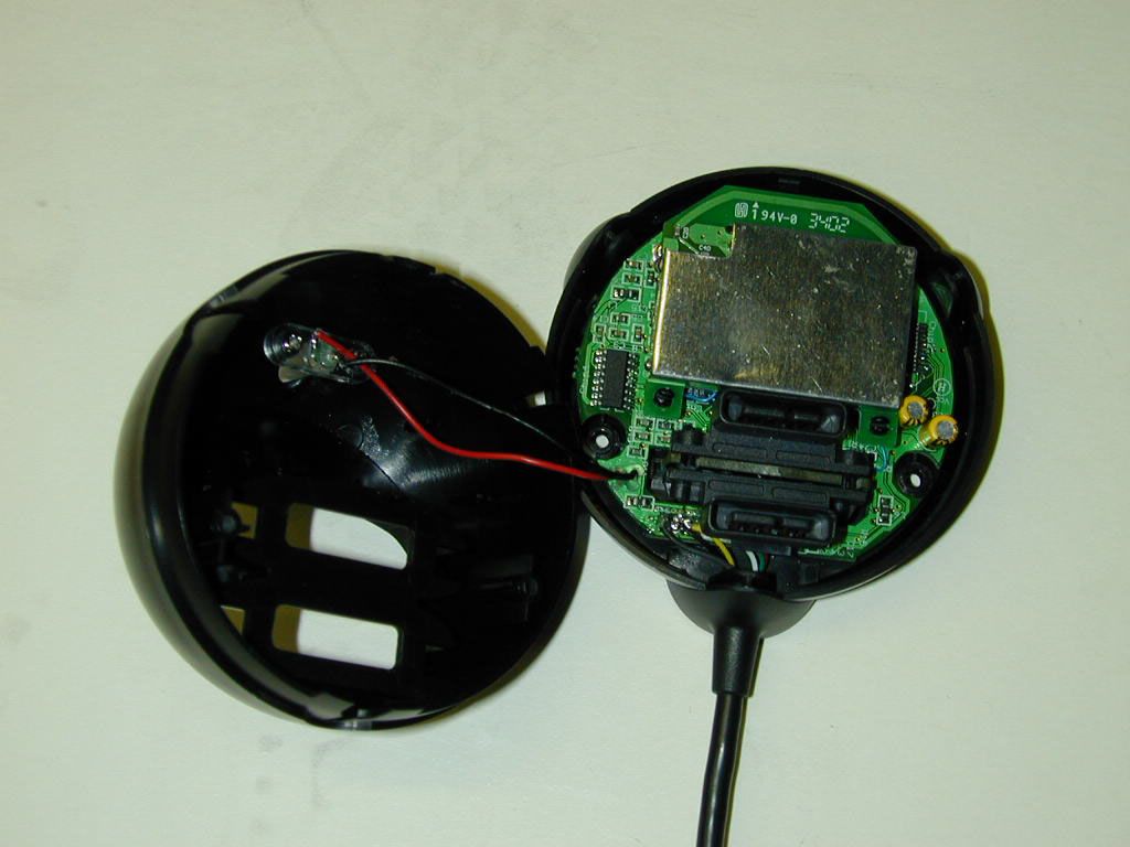
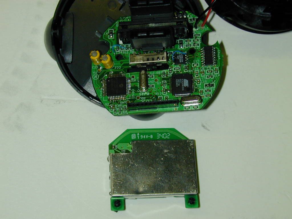
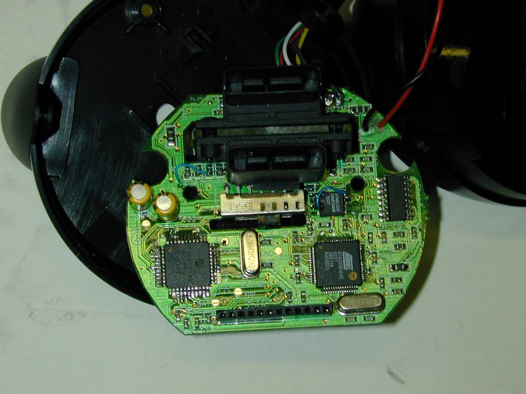
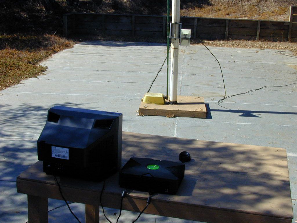
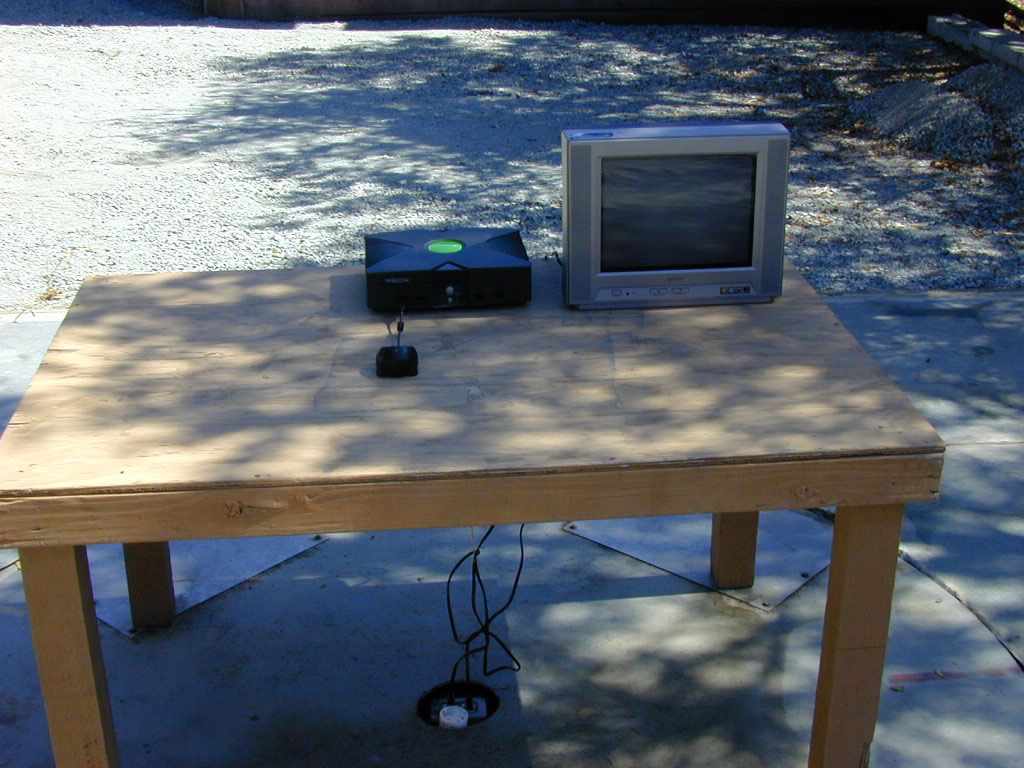
Document Text
Text extracted from the exhibit documents filed with the FCC. Open a document above to read the original.
Users Manual
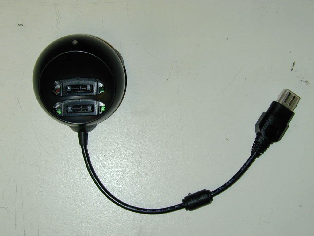
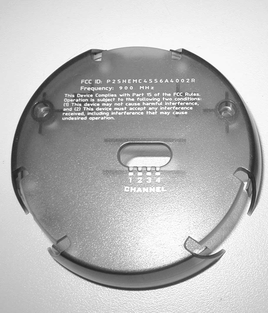
ENGLISH LYNX ™ WIRELESS CONTROLLER XBOX ™ Thank you for purchasing the Mad Catz Lynx Wireless controller for use with the Xbox video game system. The Lynx puts you in control of your game system with all the comfort of a remote controller combined with the reliability of cutting-edge wireless technology. With its "unblockable" RF signal transceivers, the Lynx lets you comfortably play from up to 40’ from your Xbox while maintaining complete control over your gaming experience. This user guide will help you understand how to use your Lynx and get the most from the features it has to offer. The Lynx is one of the most durable and reliable accessories you can buy. Be sure to visit www.madcatz.com to register your product and check out our full line of other quality video game accessories. TABLE OF CONTENTS LAYOUT 2 POWER SAVE MODE 3 MULTIPLE CONTROLLERS 3 CAUTIONS 3 TROUBLESHOOTING 4 WARRANTY 5 TECHNICAL SUPPORT 5 LAYOUT Base Unit: Used to transmit and receive data from the controller to the game console. Houses two memory card expansion slots. Directional Pad: The D-pad controls the direction in which the character moves. Analog Sticks: The two analog sticks each control two axes (X-and Y-axis). Certain software titles will allow you to modify the way that the analog sticks are used and react in the games. Triggers Buttons (L and R): These are action buttons and their specific functions depend on the software being used. Action Buttons ( A, B, X, Y, Black, White ) : These buttons are used to perform various actions, depending on the software. For more details, see the software instruction manual. Start Button: This button is generally used to make selections in the menus and for pausing the game. For more details, see the software instruction manual. Back Button: This button is used to navigate backwards in the game menus. For more details, see the software instruction manual. Channel Selector: This is used for selecting a unique channel for each player's Lynx and Base Unit Motor Control Selector: This is used to choose whether the motors are "0" (off), "1" (low intensity), or "2" (high intensity). 12 BASE UNIT CONTROLLER MEMORY CARD SLOTS MOTOR CONTROL SELECTOR CHANNEL SELECTOR ANALOG STICK ANALOG STICK BACK START WHITE BLACK ACTION BUTTONS DIRECTIONAL PA D POWER SAVE MODE The Lynx controller has an automatic “Sleep” mode -- when the controller is not in use for more than three minutes, the controller will partially turn itself off in order to conserve batteries. To wake the controller from sleep mode, press D-Pad, analog sticks, BACK button or START button of the controller. When storing the controller for extended periods of time, or while traveling with the controller, remove the batteries to conserve battery life. MULTIPLE CONTROLLERS If you want to use two or more Lynx controllers at the same time (as in multi- player games), simply plug the controllers into the game system as you normally would and begin play. Confirm that each Lynx controller has a unique player number (1,2,3 or 4) and that it matches the player number selected on the Base Unit. When you play in the multi-player mode: 1. Insert the game disk and turn on your console. 2. Insert the Base Unit for the first controller into the Player-1 Controller port on the game console. 3. Confirm the link between first Base Unit and first Lynx by using the controller to see if it works in the game or game menu. 4. Insert the Base Unit for the second Lynx into the Player-2 Controller port on the game console. 5. Confirm the link between second Base Unit and second Lynx controller by using the controller to see if it works in the game or game menu. 6. IMPORTANT – Confirm that each Lynx controller has a unique player number (channel 1,2,3 or 4) and that it matches the player number selected on the Base Unit. CAUTIONS - IMPORTANT! Before using this product read all accompanying information and your game system’s instruction manual for safety, health and other information - To prevent fire or shock hazard, do not expose this unit to rain or moisture. Do not use within 30’ of any water such as swimming pools, bathtubs, or sinks. - To avoid electrical shock, do not disassemble. Refer servicing to qualified personnel only. ENGLISH ENGLISH - This unit should be operated only from the power source indicated on the unit. If you are not sure of the type of electrical power supplied to your home, contact your local power company. - Never push objects of any kind, other than authorized items, into the product as they may touch dangerous voltage points or short out parts that could result in fire or electrical shock. - Stop using this unit immediately if you begin to feel tired or if you experience discomfort or pain in your hands and/or arms while operating the unit. If the condition persists, consult a doctor. - Do not attempt to operate the unit in any way except with your hands. Do not bring the unit in contact with your head, face, or near the bones of any other part of your body - The vibration function of this unit can aggravate injuries. Switch off or do not use the vibration function of the unit if you have any ailment of the bones or joints of your hands or arms. - Avoid prolonged use of this unit. Take breaks every 30 minutes. - Use this unit only as intended. - Do not dispose of batteries in fire. Refer to local country, state and city guidelines for appropriate methods of battery disposal. - Do not put batteries into unit backwards. - Misuse of batteries within this unit may cause batteries to leak and/or explode and lead to personal injury. - This product contains small parts that may cause choking if swallowed. Not intended for children under 3 years of age. TROUBLESHOOTING Problem: The Lynx controller does not respond. Solution: Make sure the batteries are fully charged and have not run out. Solution: Confirm that each Lynx controller has a unique player number (channel 1,2,3 or 4) and that it matches the player number selected on…
Text truncated - open the document above for the full version.
Operational Description
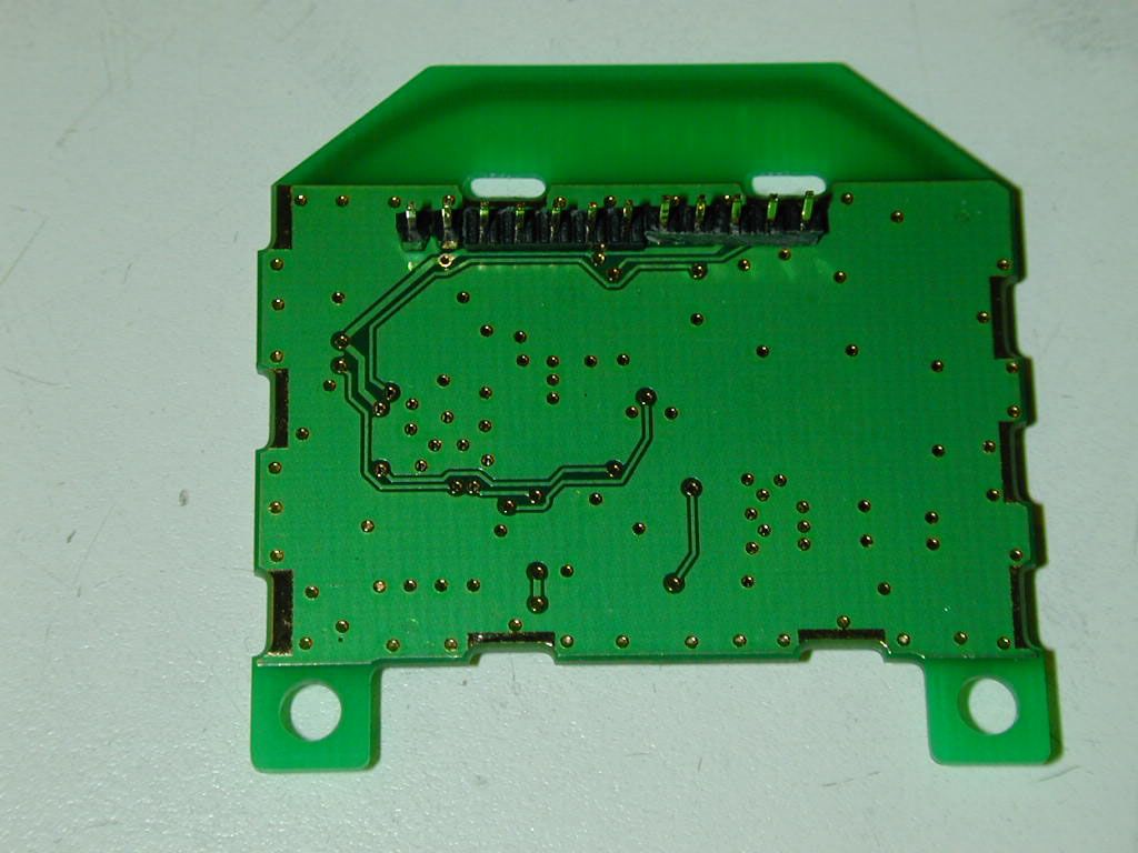
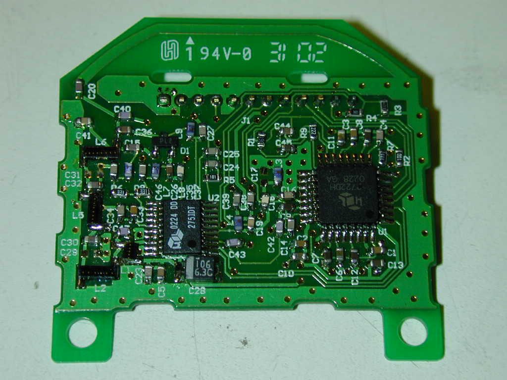
1) Frequency range The device uses ten channels in the 900 MHz ISM band, depending on the setting of the ‘player number’ switch and the current noise levels of the available channels. The RF chipset used in the device has a signal bandwidth of 1.536 MHz and the channel centers are at the following frequencies: 905.728, 907.776, 909.824, 911.872, 913.920, 915.968, 918.016, 920.064, 922.112, and 924.160 MHz. 2) Device description The device consists of two modules, a battery-powered unit which is held in the hand and has the operable controls for gameplay, and a line-powered unit which is plugged into and communicates with the game box. Since the units communicate bi-directionally it’s not accurate to use the terms ‘transmitter’ and ‘receiver’, so we use the wireless phone terms ‘handset’ and ‘base unit’ to describe the two modules. As shown on the accompanying block diagram, the handset it consists of the various game control devices (which are multiplexed into the microprocessor), two vibration motors and their associated drivers for gameplay feedback, the battery pack, a microprocessor and an RF chipset (complete with a PIN diode switch to provide half- duplex communication). The RF chipset requires a fixed 6.144 MHz reference frequency, and three times that frequency is a good clock frequency for the microprocessor, so the scheme shown is used: the microprocessor’s onboard crystal oscillator is used to generate an 18.432 MHz clock which is divided by three to give the reference clock for the RF chipset. The base unit block diagram shows that the base unit contains the same RF chipset, a microprocessor which handles the RF communications, and a microprocessor which interfaces with the game box. Two ‘downstream’ ports are provided so accessory devices (such as memory cards) can be plugged into the base unit, in accordance with the game box manufacturer’s requirements. As on the handset, a single crystal is used to generate 18.432 MHz and 6.144 MHz clocks, but the second microprocessor requires a 6.000 MHz clock so it uses a separate crystal. Since the handset is battery powered, and since communications must be bi-directional to accommodate the vibration motor commands, a packetized protocol is used in which the handset paces the transactions. To maximize battery life, the handset microprocessor places itself and the RF chipset in a sleep mode immediately after a transaction is finished. The microprocessor’s onboard sleep timer is used to wake the micro up approximately 9 mS later. At this time data is gathered from the game control devices, and the RF chipset is awakened at the appropriate time to perform its internal self- alignment process. When this is done, the data are packetized in a proprietary format and sent (using a simple FSK protocol) across the RF link to the base unit. The base unit receives the packet, decodes it to ensure the packet is valid, and returns a shorter packet to the handset which includes the vibration motor commands. Upon reception of a valid packet the handset microprocessor places itself and its RF chipset back into sleep mode until it is again awakened by the sleep timer. Both the base unit and the handset have the ability to request a re-send if the incoming packet is invalid. The entire transaction takes less than 500 uS (assuming no re-send is required). Since the base unit of the device is not battery powered, it has no sleep mode. Immediately after a successful transaction with the handset unit, the base unit RF chipset is tuned to the other available channels and an assessment is made of the relative channel noises. If another channel is available which has less noise than the current channel, the base unit will instruct the handset to change to the cleaner channel on the next packet, using a handshaking protocol to ensure both modules change channel successfully. The protocol allows the unit to change channels as often as every 70 mS, with no maximum dwell time on a given channel. This isn’t the same as frequency-hopping; at any given time all the information resides in a single channel, and the unit may never change channels at all if it finds a very clean channel. Both the handset and base unit modules will begin scanning all the available channels if no valid packets are received in a designated amount of time. To speed up the re-linking process, the handset sends out packets more frequently when it’s scanning. The base unit also scans the available channels but it simply waits to receive a valid packet, and scans the channels more slowly than the handset, ensuring that the two modules will re-link in the shortest possible time. The handset and base units use the same RF PCB, which has a trace that acts as an internal antenna. No external antenna is used. Because all RF activity is confined to a single small PCB, no complex grounding scheme is needed. All PCB’s are conventional double-sided PCB’s with ground planes occupying as much real estate as possible on both side of the boards.
Test Report
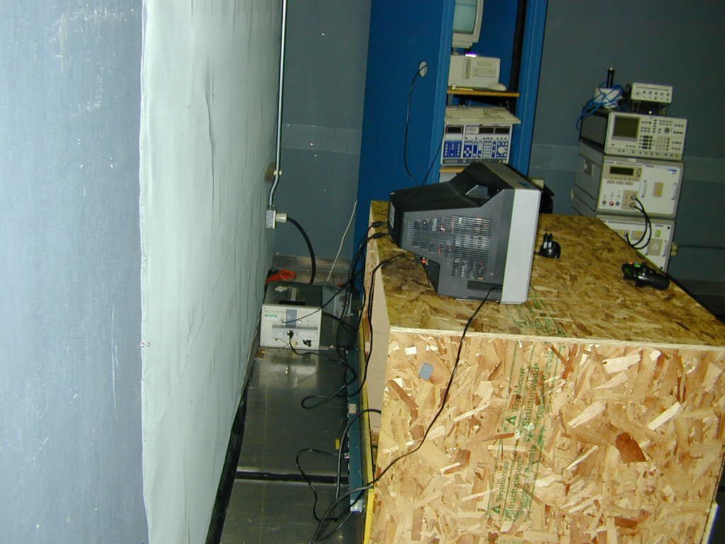
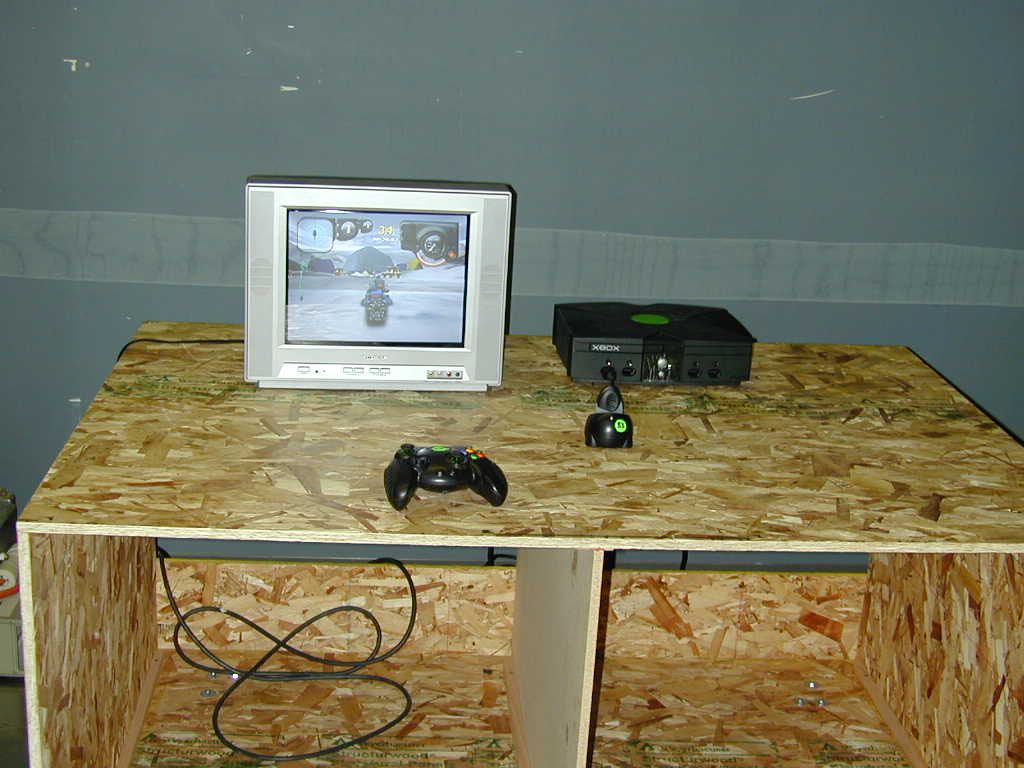
0241aMDC4556b_subc Page 1 of 31 Atlas Compliance & Engineering, Inc. 142 North Milpitas Blvd. PMB 376 Milpitas, CA 95035 Phone 831.761.2223 Fax 831.761.3223 .......... Atlas Compliance & Engineering, Inc. FCC Test Report FCC CFR 47 Part 15.207 and 15.249 COMPLIANCE Mad Catz 7480 Mission Valley Rd. Suite 101 San Diego, CA 92108 USA Product: Xbox RF Controller Base Model: 4556 Test Report Number:0241aMDC4556b_subc Date of Report:October 7, 2002 This report contains 31 pages and may be reproduced in full only. Partial reproduction may only be done with the written consent of Atlas Compliance & Engineering, Inc. 0241aMDC4556b_subc Page 2 of 31 Atlas Compliance & Engineering, Inc. 142 North Milpitas Blvd. PMB 376 Milpitas, CA 95035 Phone 831.761.2223 Fax 831.761.3223 Table of Contents Table of Contents............................................................................................................................................2 General Information........................................................................................................................................3 Test Equipment...............................................................................................................................................4 Test Configuration..........................................................................................................................................5 EUT Description / Note:..............................................................................................................................5 EUT Support Program.................................................................................................................................5 EUT Modifications for Compliance.............................................................................................................5 EUT Support Devices..................................................................................................................................6 I/O Ports and Cables....................................................................................................................................6 Equipment Under Test.....................................................................................................................................7 Equipment Block Diagram............................................................................................................................14 Test Setup (Radiated Emissions)....................................................................................................................15 Test Setup (Conducted Emissions).................................................................................................................17 Test Methods for Emissions.......................................................................................................................19 Conducted Emission Testing......................................................................................................................19 Temperature and Humidity........................................................................................................................20 Sample Calculations..................................................................................................................................20 FCC Part 15 Subpart C 15.207 and 15.249 Limits..........................................................................................21 Report of Measurements Radiated Data.....................................................................................................22 Conducted Data for FCC Part 15.207(a), Line............................................................................................23 Conducted Data for FCC Part 15.207(a), Neutral........................................................................................24 COMPLIANCE VERIFICATION REPORT..................................................................................................25 Table 1 - Support Equipment Used For Test.....................................................................................................6 Table 2 - EUT Port Termination’s....................................................................................................................6 Table 3 - Host Port Termination's....................................................................................................................6 Table 4 - Radiated Emission Limits, Operation within the bands 902 – 928 MHz, 2400 – 2483.5 MHz, 5725 – 5875 MHz, and 24.0 – 24.25 GHz..........................................................................................................21 Table 5 - Conducted Limits...........................................................................................................................21 Table 6 - Radiated Emission Level.................................................................................................................22 Table 7 - Line Scan Data...............................................................................................................................23 Table 8 - Neutral Scan Data...........................................................................................................................24 Figure 1 - Test Setup Diagram.......................................................................................................................14 Figure 2 - Line Scan......................................................................................................................................23 Figure 3 - Neutral Scan..................................................................................................................................24 0241aMDC4556b_subc Page 3 of 31 Atlas Compliance & Engineering, Inc. 142 North Milpitas Blvd. PMB 376 Milpitas, CA 95035 Phone 831.761.2223 Fax 831.761.3223 General Information Test Rep…
Text truncated - open the document above for the full version.
Contact Information
Applicant
Parco Liu(Quality Manager)
Technical Contact
Mad Catz, Inc.Dave Preller
[email protected]619-683-9830
7480 Mission Valley Rd. · San Diego, California · United States
Non-Technical Contact
Mad Catz, Inc.Dave Preller
[email protected]619-683-9830
Test Firm
Atlas Compliance & Engineering, Inc.Bruce Smith
Technical Specifications
| # | Rule Parts | Frequency Range | Power Output |
|---|---|---|---|
| 1 | 15C | 905.75 MHz - 924.18 MHz | - |
Other Applications from Mad Catz, Inc.
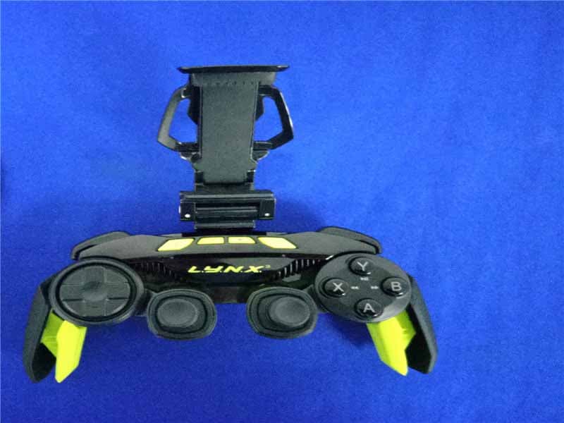
P25SS32269A
Aug 31, 2015Mad Catz L.Y.N.X.3 Mobile Wireless Controller
Equipment Class
DSS - Part 15 Spread Spectrum Transmitter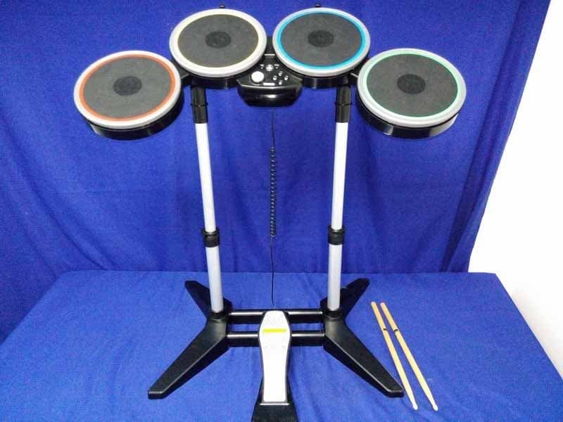
P25M991262A
Jun 24, 2015Rock Band 4 Wireless Drum Set for PlayStation 4
Equipment Class
DSS - Part 15 Spread Spectrum Transmitter
P25M991261A
Jun 02, 2015Rock Band 4 Wireless Fender Stratocasterfor PlayStation 4
Equipment Class
DSS - Part 15 Spread Spectrum Transmitter
P25SS32272A
Apr 25, 2015Mad Catz S.U.R.F.R
Equipment Class
DSS - Part 15 Spread Spectrum Transmitter
P25R232267A
Mar 03, 2015L.Y.N.X.9 Mobile Hybrid Controller
Equipment Class
DSS - Part 15 Spread Spectrum Transmitter