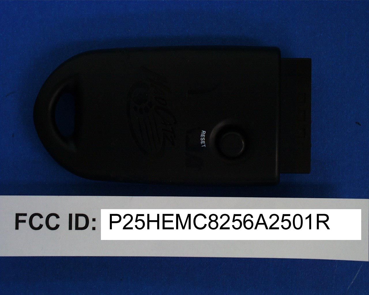
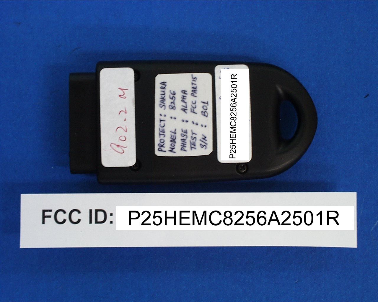
P25HEMC8256A2501RRemotre Control for Playstation 2
Mad Catz, Inc.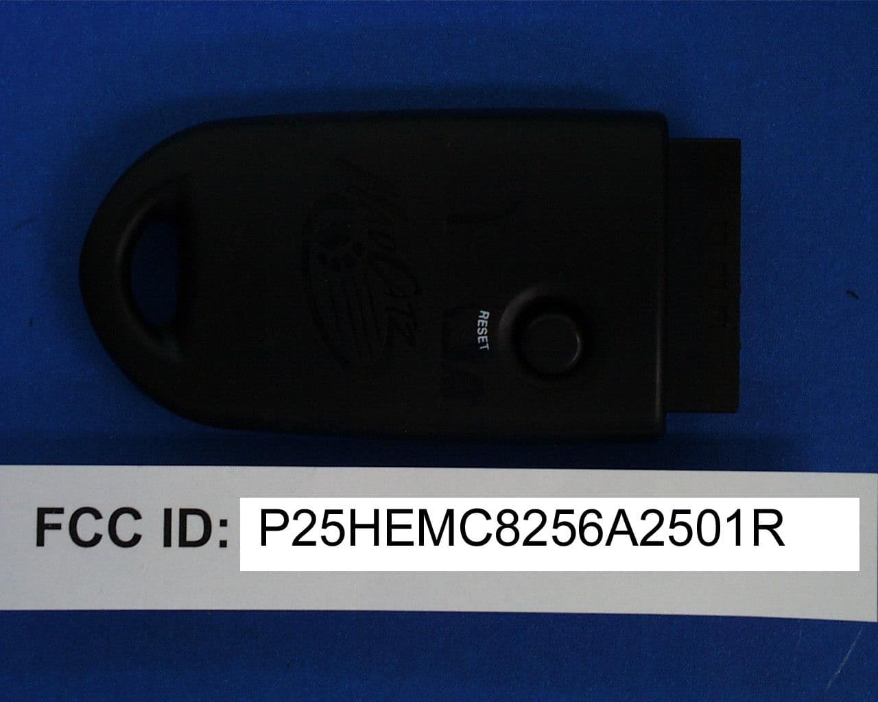
Click to zoom
Application Details
- Equipment Class
- DXX - Part 15 Low Power Communication Device Transmitter
- Date of Grant
- Dec 13, 2001
- Application Purpose
- Original Equipment
- Date of Application
- Dec 13, 2001
- Equipment Note
- Remotre Control for Playstation 2
- Frequency Range
- 902.20000000 - 902.20000000
- Company
- Mad Catz, Inc.
- Country
- United States
Documents & Files
Document Text
Text extracted from the exhibit documents filed with the FCC. Open a document above to read the original.
Users Manual
ENGLISH 900MHz DUAL FORCE 2 ™ CONTROLLER PLAYSTATION ® 2, PSONE ™ and PLAYSTATION ® Thank you for purchasing the Mad Catz 900MHz Dual Force 2 controller for use with the PlayStation 2/PlayStation/PS one video game system. The 900 MHz Wireless Dual Force 2 controller puts you in control of your game system with all the comfort of a remote controller combined with the reliability of cutting-edge wireless technology. With its ‘unblockable” RF signal transceivers, the 900MHz Dual Force 2 lets you comfortably play from up to 40’ from your PlayStation 2/PlayStation/PS one while maintaining complete control over your gaming experience. This user guide will help you understand how to use your 900MHz Dual Force 2 controller and get the most from the features it has to offer. The 900MHz Dual Force 2 controller is one of the most durable and reliable accessories you can buy. Be sure to visit www.madcatz.com to register your product and check out our full line of other quality video game accessories. TABLE OF CONTENTS SET-UP 2 LAYOUT 2 CONTROL MODES 4 MULTIPLE CONTROLLERS 5 RESETTING THE CONTROLLER 5 PROGRAMMING MACROS 6 CAUTIONS 9 TROUBLESHOOTING 9 TECHNICAL SUPPORT 9 WARRANTY 10 SET-UP 1. Plug-in the Charge Dock. 2. Place the controller in the Charge Dock. Allow the controller to charge for ten hours before initial use. The Mode Button will slowly flash amber while charging. Additionally, while you are using the controller and the battery life is low, the Mode Button will flash amber at a quicker rate – this indicates the battery has 30 minutes of life remaining. 3. Turn off the power to your game console. 4. Insert the Antenna Receiver into the controller port on the game console. 5. Turn on the power to your game console and begin play. LAYOUT 12 Reciever L1 (above) L2 (below) R1 (above) R2 (below) Directional Pad Controller L3 (press down) Macro Mode Start Action Buttons Select R3 (press down) Charge Dock Reset Charge Dock: Used to recharge the 900MHz Dual Force 2 controller. While recharging, the [MODE] Button will flash amber. If the [MODE] Button is not flashing, the controller is not making proper contact with the Charge Dock. A fully charged battery should last up to five hours. To fully charge a battery, leave the controller in the Charge Dock for 10 hours for the first time. For maximum battery life, run the controller battery all the way down before recharging. When the controller is fully charged, the MODE LED will turn clear. Antenna Receiver: Used to transmit and receive data from the controller to the game console. Directional Pad: The D-pad controls the direction in which the character moves. This is the primary directional control while in Digital Mode. Analog Sticks: The two analog sticks each control two axes (X-and Y-axis). Different software titles will allow you to modify the way that the analog sticks react in the games. While in Analog Mode, any software title that is Vibration Function Compatible will cause the 900MHz Dual Force 2 controller to vibrate at different levels, depending on actions taking place from within the game (e.g., being hit, crashing, or shooting). NOTE : NOT ALL GAMES ARE VIBRATION FUNCTION COMPATIBLE. LOOK FOR THE “VIBRATION FUNCTION COMPATIBLE” ICON ON THE BACK OF THE PACKAGE OR INSTRUCTION MANUAL FOR THE GAME THAT YOU ARE PLAYING. Shoulder Buttons (L1, L2, R1, and R2): These are action buttons and their specific functions depend on the software being used. Action Buttons ( ) : These buttons are used to perform various actions, depending on the software. For more details, see the software instruction manual. Start Button: This button is generally used to make selections in the menus and for pausing the game. For more details, see the software instruction manual. Select Button: This is a standard button that allows you to do various things, depending on the software. For more details, see the software instruction manual. ENGLISH ENGLISH Mode Button: The 900MHz Dual Force 2 controller has three different modes; Analog Controller Mode, Steering Wheel Mode and Digital Mode. The current mode is indicated by the color of the [MODE] Button on the faceplate of the controller: Green Light - STEERING WHEEL MODE Red Light - ANALOG MODE Light Off - DIGITAL MODE (Refer to “CONTROL MODES” for instructions on this feature.) Macro Button: Used for recording a series of commands to a single button. (Refer to “PROGRAMMING MACROS” for instructions on this feature.) Reset Button: The Antenna Receiver unit features a [RESET] button. The [RESET] button will tell the Antenna Receiver to find a new clear transmission channel if interference is experienced. Refer to “RESETTING THE CONTROLLER” for instructions on this feature. CONTROL MODES There are three different control modes from which you can choose, depending on your style of play. Change control modes by pressing the Mode button. The color of the lighted Mode button tells you which mode you are in: Analog Controller Mode - RED light This is the standard “Dual Shock™” mode. Some games will only vibrate if the controller is in Analog Controller mode. Steering Wheel Mode - GREEN light This mode is best for driving games that use Steering Wheel (or NeGcon™) protocols. Some games will allow you to calibrate from within the software. This will allow the user to adjust the sensitivity from within the game. This sensitivity and adjustment feature is only available in Steering Wheel mode. Digital Mode - Light OFF This is the original PlayStation controller mode. This is the default control mode. 34 ENGLISHENGLISH MULTIPLE CONTROLLERS If you want to use two or more 900MHz Dual Force 2 controllers at the same time (as in multi-player games or with the Mad Catz PS2 Multi-Tap™), simply plug the controllers into the game system as you normally would and begin play. You don’t need to set any buttons or switches. The Mad Catz Wireless Dual Force 2 controller uses AUTOMATIC CHANNEL RECOGNITION and AUTOMATIC ID RECOGNITION to automatic…
Text truncated - open the document above for the full version.
Operational Description
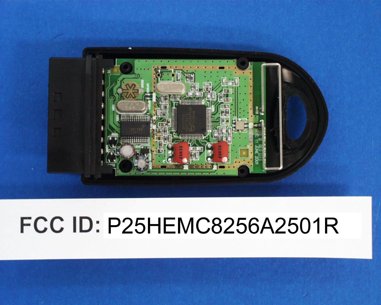
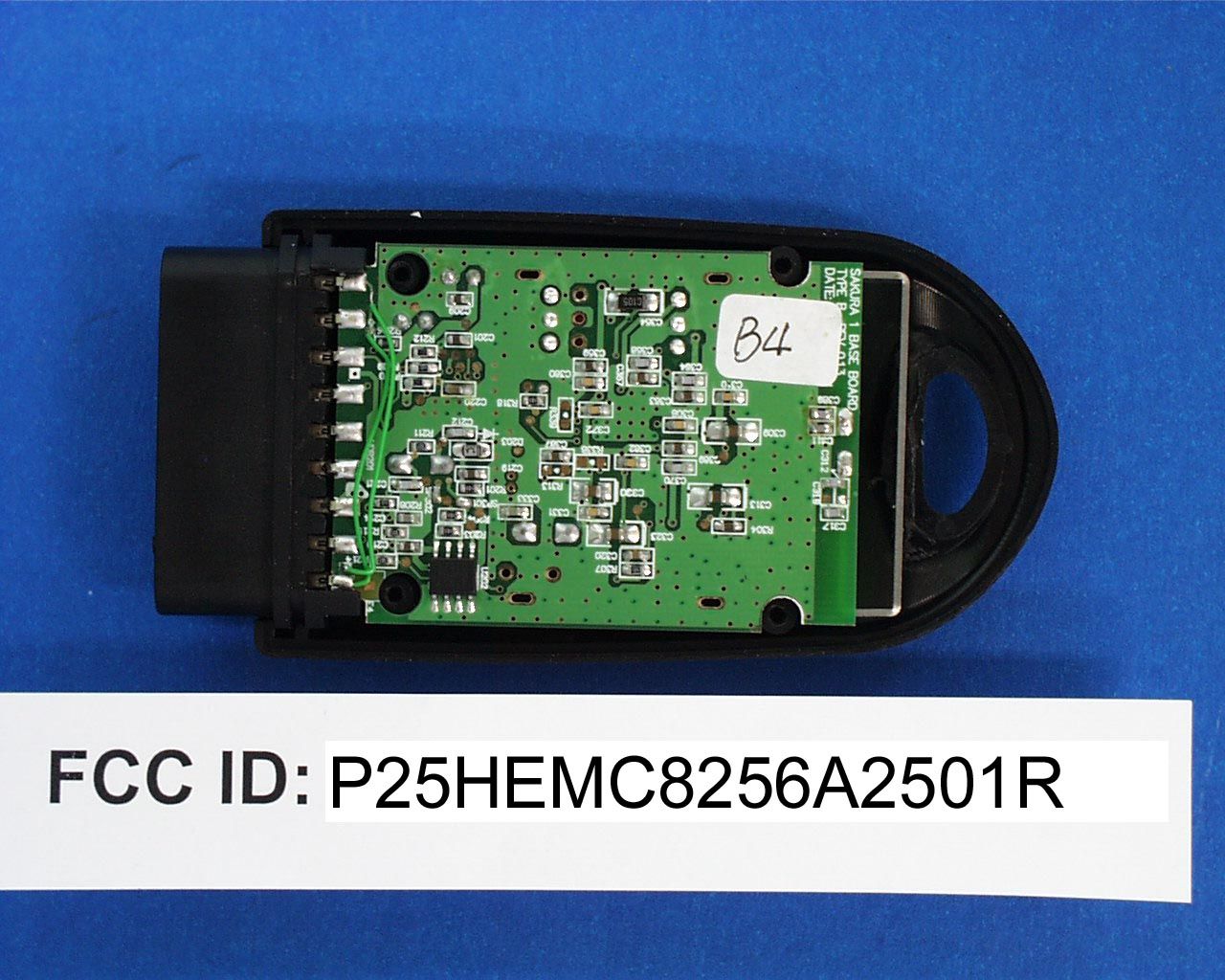
FCC ID: P25HEMC8256A2501R Operation Description: The equipment under test (EUT) is a transmitter for Remote Control For Playstation 2 operating at 902.200 MHz which is controlled by a crystal. The EUT is powered by the Playstation 2. The Power to Sakura Base is derived from the PS2 console. The 8V line from the PS2 console (at PS2 Connector), is regulated by VR201 voltage regulator and supplied to the Base circuit (VCCRF). The Digital Communication signals between PS2 console and Base is via 5 wire serial interface. The MCU, U201 receives the information from PS2 and is send to the RF IC, U301. This data is modulated on an RF carrier and will be radiated through the Antenna. The signals from the controller is received at the antenna and fed to U301 and demodulated Data is send to U201. U201 in-turn send this data to PS2 console via the Serial data communication link. SW201, Sync button is used to synchronize the Base and the Controller. Circuit Description: The brief circuit description is listed as follows: - VR201 and associated circuit act as Voltage Regulator. - U202 and associated circuit act as EEPROM. - U201 and associated circuit act as MCU. - U301, X301 and associated circuit act as RF IC and Local Oscillator. - U302 and associated circuit act as RF Duplexer. Antenna Used: A permanent internal wire antenna has been used.
Test Report
• The test results reported in this report shall refer only to the sample actually tested and shall not refer or be deemed to refer to bulk from which such a sample may be said to have been obtained. • This report shall not be reproduced except in full without prior authorization from Intertek Testing Services Hong Kong Limited FCC ID : P25HEMC8256A2501R Mad Catz (Asia) Ltd. Application For Certification (FCC ID: P25HEMC8256A2501R) Transmitter, Model : 8256 We hereby certify that the sample of the above item is considered to comply with the requirements of FCC Part 15, Subpart C for Intentional Radiator, mention 47 CFR [10-1-99 edition] WO# 0108028 WN/at November 19, 2001 INTERTEK TESTING SERVICES FCC ID: P25HEMC8256A2501R i LIST OF EXHIBITS INTRODUCTION EXHIBIT 1:General Description EXHIBIT 2:System Test Configuration EXHIBIT 3:Emission Results EXHIBIT 4:Equipment Photographs EXHIBIT 5:Product Labelling EXHIBIT 6:Technical Specifications EXHIBIT 7:Instruction Manual EXHIBIT 8:Miscellaneous Information INTERTEK TESTING SERVICES FCC ID: P25HEMC8256A2501R ii MEASUREMENT/TECHNICAL REPORT Mad Catz (Asia) Ltd. - MODEL: 8256 FCC ID: P25HEMC8256A2501R November 19, 2001 This report concerns (check one:)Original Grant X Class II Change Equipment Type: Low Power Transmitter (example: computer, printer, modem, etc.) Deferred grant requested per 47 CFR 0.457(d)(1)(ii)?Yes No X If yes, defer until: date Company Name agrees to notify the Commission by: date of the intended date of announcement of the product so that the grant can be issued on that date. Transition Rules Request per 15.37?Yes No X If no, assumed Part 15, Subpart C for intentional radiator Report prepared by:Wilbur Ng Intertek Testing Services 2/F., Garment Center, 576, Castle Peak Road, HONG KONG Phone:852-2173-8502 Fax:852-2742-9149 INTERTEK TESTING SERVICES FCC ID: P25HEMC8256A2501R iii Table of Contents 1.0 General Description.......................................................................................................................2 1.1 Product Description...................................................................................................................2 1.2 Related Submittal(s) Grants.....................................................................................................2 1.3 Test Methodology......................................................................................................................3 1.4 Test Facility...............................................................................................................................3 2.0 System Test Configuration............................................................................................................5 2.1 Justification...............................................................................................................................5 2.2 EUT Exercising Software..........................................................................................................5 2.3 Special Accessories....................................................................................................................5 2.4 Equipment Modification...........................................................................................................6 2.5 Support Equipment List and Description.................................................................................6 3.0 Emission Results............................................................................................................................8 3.1 Field Strength Calculation........................................................................................................9 3.1 Field Strength Calculation (cont’d).........................................................................................10 3.2 Radiated Emission Configuration Photograph......................................................................11 3.3 Radiated Emission Data.........................................................................................................12 4.0 Equipment Photographs.............................................................................................................15 5.0 Product Labelling.........................................................................................................................17 6.0 Technical Specifications..............................................................................................................19 7.0 Instruction Manual......................................................................................................................21 8.0 Miscellaneous Information.........................................................................................................23 8.1 Measured Bandwidth..............................................................................................................24 8.2 Emissions Test Procedures.....................................................................................................25 8.2 Emissions Test Procedures (cont'd)........................................................................................26 INTERTEK TESTING SERVICES FCC ID: P25HEMC8256A2501R iv List of attached file Exhibit typeFile Descriptionfilename Test ReportTest Reportreport.pdf Operation DescriptionTechnical Descriptiondescri.pdf Test Setup PhotoRadiated Emissionradiated1.jpg to radiated2.jpg Test ReportBandwidth Plotbw.pdf External PhotoExternal Photoophoto1.jpg to ophoto2.jpg Internal PhotoInternal Photoiphoto1.jpg to iphoto2.jpg Block DiagramBlock Diagramblock.pdf SchematicsCircuit Diagramcircuit.pdf ID Label/LocationLabel Artwork and Locationlabel.pdf User ManualUser Manualmanual.pdf INTERTEK TESTING SERVICES FCC ID: P25HEMC8256A2501R 1 EXHIBIT 1 GENERAL DESCRIPTION INTERTEK TESTING SERVICES FCC ID: P25HEMC8256A2501R 2 1.0General Description 1.1Product Description The equipment under test (EUT) is a transmitter for Remote Control Fo…
Text truncated - open the document above for the full version.
Contact Information
Applicant
Parco Liu(Quality Manager)
Technical Contact
Intertek Testing Services Hong Kong Ltd.Wilbur Ng
[email protected]852 2173 8502
2/F, Garment Centre · Kowloon · Hong Kong
Non-Technical Contact
Intertek Testing Services Hong Kong Ltd.Wilbur Ng
[email protected]852 2173 8502
Test Firm
Intertek Testing Services Hong KongBilly Chow
Technical Specifications
| # | Rule Parts | Frequency Range | Power Output |
|---|---|---|---|
| 1 | 15C | 902.2 MHz - 902.2 MHz | - |
Other Applications from Mad Catz, Inc.
P25SS32269A
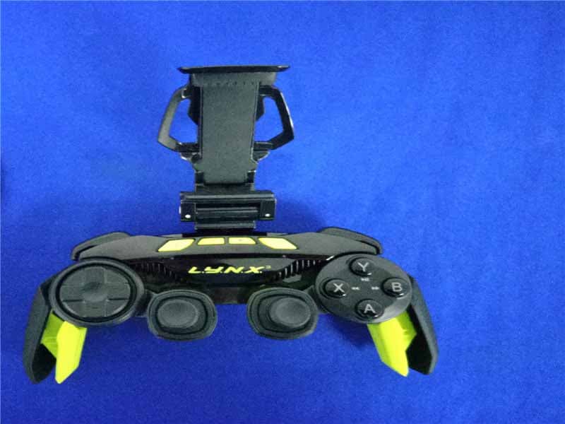
Aug 31, 2015Mad Catz L.Y.N.X.3 Mobile Wireless Controller
Equipment Class
DSS - Part 15 Spread Spectrum Transmitter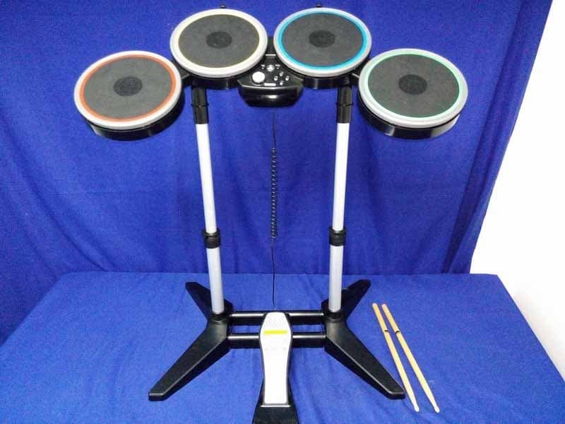
P25M991262A
Jun 24, 2015Rock Band 4 Wireless Drum Set for PlayStation 4
Equipment Class
DSS - Part 15 Spread Spectrum Transmitter
P25M991261A
Jun 02, 2015Rock Band 4 Wireless Fender Stratocasterfor PlayStation 4
Equipment Class
DSS - Part 15 Spread Spectrum Transmitter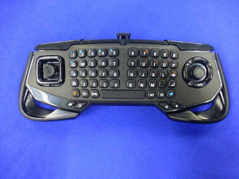
P25SS32272A
Apr 25, 2015Mad Catz S.U.R.F.R
Equipment Class
DSS - Part 15 Spread Spectrum Transmitter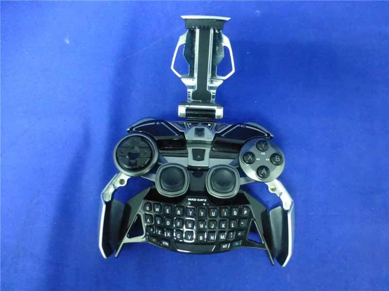
P25R232267A
Mar 03, 2015L.Y.N.X.9 Mobile Hybrid Controller
Equipment Class
DSS - Part 15 Spread Spectrum Transmitter