P25L790631AMad Catz Tritton Swarm Mobile Wireless Headset
Mad Catz, Inc.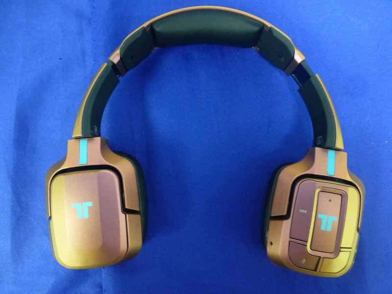
Click to zoom
Application Details
- Equipment Class
- DSS - Part 15 Spread Spectrum Transmitter
- Date of Grant
- Dec 29, 2014
- Application Purpose
- Original Equipment
- Date of Application
- Dec 29, 2014
- Equipment Note
- Mad Catz Tritton Swarm Mobile Wireless Headset
- Frequency Range
- 2402.00000000 - 2480.00000000
- Company
- Mad Catz, Inc.
- Country
- United States
Documents & Files
Document Text
Text extracted from the exhibit documents filed with the FCC. Open a document above to read the original.
Users Manual
Mad Catz Tritton Swarm Mobile Wireless Headset Size: 100 (W) x 100 (H)mm Material: 128gsm Double Side Art Paper Color: 1C + 1C Coating: Vernish Date: 21-Nov-2014 Warning To prevent possible hearing damage, do not listen at high volume levels for long periods. This device complies with Part 15 of the FCC Rules. Operation is subject to the following two conditions: (1) this device may not cause harmful interference, and (2) this device must accept any interference received, including interference that may cause undesired operation. Changes or modifications not expressly approved by the party responsible for compliance could void the user's authority to operate the equipment NOTE:THE MANUFACTURER IS NOT RESPONSIBLE FOR ANY RADIO OR TV INTERFERENCE CAUSED BY UNAUTHORIZED MODIFICATIONS TO THIS EQUIPMENT.SUCH MODIFICATIONS COULD VOID THE USER’S AUTHORITY TO OPERATE THE EQUIPMENT NOTE: This equipment has been tested and found to comply with the limits for a Class B digital device, pursuant to Part 15 of the FCC Rules. These limits are designed to provide reasonable protection against harmful interference in a residential installation. This equipment generates, uses and can radiate radio frequency energy and, if not installed and used in accordance with the instructions, may cause harmful interference to radio communications. However, there is no guarantee that interference will not occur in a particular installation. If this equipment does cause harmful interference to radio or television reception, which can be determined by turning the equipment off and on, the user is encouraged to try to correct the interference by one or more of the following measures: - Reorient or relocate the receiving antenna. - Increase the separation between the equipment and receiver. - Connect the equipment into an outlet on a circuit different from that to which the receiver is connected. - Consult the dealer or an experienced radio/TV technician for help. This equipment complies with FCC RF radiation exposure limits set forth for an uncontrolled environment. This device complies with Industry Canada licence-exempt RSS 210 standard(s). Operation is subject to the following two conditions: (1) this device may not cause interference, and (2) this device must accept any interference, including interference that may cause undesired operation of the device Le présent appareil est conforme aux CNR d'Industrie Canada applicables aux appareils radio exempts de licence. L'exploitation est autorisée aux deux conditions suivantes : (1) l'appareil ne doit pas produire de brouillage, et (2) l'utilisateur de l'appareil doit accepter tout brouillage radioélectrique subi, même si le brouillage est susceptible d'en compromettre le fonctionnement. Complies with the Canadian ICES-003 Class B specifications. Cet appareil numérique de la classe B est conforme à la norme NMB-003 du Canada. CAUTION RISK OF EXPLOSION IF BATTERY IS REPLACED BY AN INCORRECT TYPE. DISPOSE OF USED BATTERIES ACCORDING TO THE INSTRUCTIONS. FrontBack TRI90631-R0
External Photos
R AUDIX Technology (Shenzhen) Co., Ltd. FCC ID:P25L790631A page Audix Technology (Shenzhen) Co., Ltd. Report No. ACS-F14342 14-1 14. PHOTOS OF THE EUT Figure 1 General Appearance of the EUT Figure 2 General Appearance of the EUT
Internal Photos
R AUDIX Technology (Shenzhen) Co., Ltd. FCC ID:P25L790631A page Audix Technology (Shenzhen) Co., Ltd. Report No. ACS-F14342 14-2 Figure 3 Inside of the EUT Figure 4 Inside of the EUT R AUDIX Technology (Shenzhen) Co., Ltd. FCC ID:P25L790631A page Audix Technology (Shenzhen) Co., Ltd. Report No. ACS-F14342 14-3 Figure 5 Inside of the EUT Figure 6 Component side of the PCB R AUDIX Technology (Shenzhen) Co., Ltd. FCC ID:P25L790631A page Audix Technology (Shenzhen) Co., Ltd. Report No. ACS-F14342 14-4 Figure 7 Component side of the PCB Figure 8 Component side of the PCB R AUDIX Technology (Shenzhen) Co., Ltd. FCC ID:P25L790631A page Audix Technology (Shenzhen) Co., Ltd. Report No. ACS-F14342 14-5 Figure 9 Component side of the PCB Figure 10 Component side of the PCB R AUDIX Technology (Shenzhen) Co., Ltd. FCC ID:P25L790631A page Audix Technology (Shenzhen) Co., Ltd. Report No. ACS-F14342 14-6 Figure 11 Component side of the PCB Figure 12 Component side of the PCB R AUDIX Technology (Shenzhen) Co., Ltd. FCC ID:P25L790631A page Audix Technology (Shenzhen) Co., Ltd. Report No. ACS-F14342 14-7 Figure 13 Cable of the EUT
RF Exposure Info
RF Exposure evaluation According to 447498 D01 General RF Exposure Guidance v05 The 1-g and 10-g SAR test exclusion thresholds for 100 MHz to 6 GHz at test separation distances ≤ 50 mm are determined by: [(max. power of channel, including tune-up tolerance, mW)/(min. test separation distance, mm)] ·[√f(GHz)] ≤ 3.0 for 1-g SAR and ≤ 7.5 for 10-g extremity SAR, where f(GHz) is the RF channel transmit frequency in GHz Power and distance are rounded to the nearest mW and mm before calculation The result is rounded to one decimal place for comparison Worse case is as below: [2.402MHz 7.174 dBm(5.217 mW) output power] (5.217mW /5mm) ·[√2.402(GHz)]= 1.6164 <3.0 for 1-g SAR Then SAR evaluation is not required
Test Report
R AUDIX Technology (Shenzhen) Co., Ltd. FCC ID:P25L790631A Audix Technology (Shenzhen) Co., Ltd. Report No. ACS-F14342 FCC PART 15C TEST REPORT FOR CERTIFICATION On Behalf of Mad Catz, Inc. Mad Catz Tritton Swarm Mobile Wireless Headset Model Number: 90631 FCC ID: P25L790631A Prepared for : Mad Catz, Inc. 10680 Treena Street Suite 500 San Diego, CA 92131 Prepared By : Audix Technology (Shenzhen) Co., Ltd. No. 6, Ke Feng Rd., 52 Block, Shenzhen Science & Industrial Park, Nantou, Shenzhen, Guangdong, China Tel: (0755) 26639496 Report Number ACS-F14342 Date of Test Oct.15~23, 2014 Date of Report Nov.18, 2014 R AUDIX Technology (Shenzhen) Co., Ltd. FCC ID:P25L790631A Audix Technology (Shenzhen) Co., Ltd. Report No. ACS-F14342 TABLE OF CONTENTS Description Page 1. SUMMARY OF STANDARDS AND RESULTS ......................................................... 1-1 1.1. Description of Standards and Results................................................................................... 1-1 2. GENERAL INFORMATION ......................................................................................... 2-1 2.1. Description of Device (EUT) ............................................................................................... 2-1 2.2. Test information ................................................................................................................... 2-2 2.3. Tested Supporting System Details ....................................................................................... 2-2 2.4. EUT Configuration and operation conditions for test. ......................................................... 2-2 2.5. Test Facility.......................................................................................................................... 2-3 2.6. Measurement Uncertainty (95% confidence levels, k=2) .................................................... 2-3 3. POWER LINE CONDUCTED EMISSION TEST....................................................... 3-1 3.1. Test Equipments................................................................................................................... 3-1 3.2. Block Diagram of Test Setup ............................................................................................... 3-1 3.3. Power Line Conducted Emission Test Limits ...................................................................... 3-1 3.4. Configuration of EUT on Test ............................................................................................. 3-2 3.5. Operating Condition of EUT................................................................................................ 3-2 3.6. Test Procedure...................................................................................................................... 3-2 3.7. Power Line Conducted Emission Test Results..................................................................... 3-2 4. RADIATED EMISSION MEASUREMENT ................................................................ 4-1 4.1. Test Equipment .................................................................................................................... 4-1 4.2. Block Diagram of Test Setup ............................................................................................... 4-1 4.3. Radiated Emission Limit Standard: FCC 15.209 ................................................................. 4-2 4.4. EUT Configuration on Test.................................................................................................. 4-2 4.5. Operating Condition of EUT................................................................................................ 4-3 4.6. Test Procedure...................................................................................................................... 4-3 4.7. Radiated Emission Test Results ........................................................................................... 4-3 5. CONDUCTED SPURIOUS EMISSIONS ..................................................................... 5-1 5.1. Test Equipment .................................................................................................................... 5-1 5.2. Limit ..................................................................................................................................... 5-1 5.3. Test Procedure...................................................................................................................... 5-1 5.4. Test result ............................................................................................................................. 5-1 6. CARRIER FREQUENCY SEPARATION TEST ........................................................ 6-1 6.1. Test Equipment .................................................................................................................... 6-1 6.2. Limit ..................................................................................................................................... 6-1 6.3. Test Results. ......................................................................................................................... 6-1 7. 20 DB BANDWIDTH TEST ........................................................................................... 7-1 7.1. Test Equipment .................................................................................................................... 7-1 7.2. Limit ..................................................................................................................................... 7-1 7.3. Test Results .......................................................................................................................... 7-1 8. NUMBER OF HOPPING FREQUENCY TEST .......................................................... 8-1 8.1. Test Equipment .................................................................................................................... 8-1 8.2. Limit ..........................…
Text truncated - open the document above for the full version.
Test Setup Photos
R AUDIX Technology (Shenzhen) Co., Ltd. FCC ID:P25L790631A page Audix Technology (Shenzhen) Co., Ltd. Report No. ACS-F14342 13-1 13. PHOTOGRAPH OF TEST 13.1. Photos of Radiated Emission Test R AUDIX Technology (Shenzhen) Co., Ltd. FCC ID:P25L790631A page Audix Technology (Shenzhen) Co., Ltd. Report No. ACS-F14342 13-2 13.2.Photos of Radiated Emission Test 30-1000MHz R AUDIX Technology (Shenzhen) Co., Ltd. FCC ID:P25L790631A page Audix Technology (Shenzhen) Co., Ltd. Report No. ACS-F14342 13-3 Above 1000MHz
Contact Information
Applicant
Parco Liu(Quality Manager)
Test Firm
Audix Technology (Shenzhen) Co., Ltd.Smart Tsai
Technical Specifications
| # | Rule Parts | Frequency Range | Power Output |
|---|---|---|---|
| 1 | 15C | 2.40 GHz - 2.48 GHz | 5.22 mW |
Other Applications from Mad Catz, Inc.
P25SS32269A
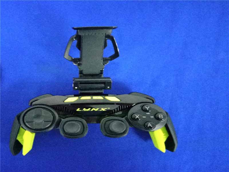
Aug 31, 2015Mad Catz L.Y.N.X.3 Mobile Wireless Controller
Equipment Class
DSS - Part 15 Spread Spectrum Transmitter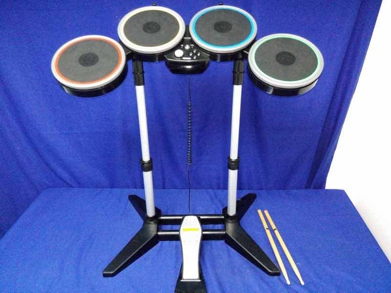
P25M991262A
Jun 24, 2015Rock Band 4 Wireless Drum Set for PlayStation 4
Equipment Class
DSS - Part 15 Spread Spectrum Transmitter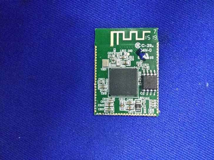
P25M991261A
Jun 02, 2015Rock Band 4 Wireless Fender Stratocasterfor PlayStation 4
Equipment Class
DSS - Part 15 Spread Spectrum Transmitter
P25SS32272A
Apr 25, 2015Mad Catz S.U.R.F.R
Equipment Class
DSS - Part 15 Spread Spectrum Transmitter
P25R232267A
Mar 03, 2015L.Y.N.X.9 Mobile Hybrid Controller
Equipment Class
DSS - Part 15 Spread Spectrum Transmitter