P25S790630ARUNIV Tritton Headset Wireless Stereo Kunai (dongle)
Mad Catz, Inc.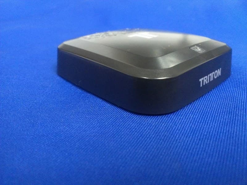
Click to zoom
Application Details
- Equipment Class
- DXX - Part 15 Low Power Communication Device Transmitter
- Date of Grant
- Feb 06, 2014
- Application Purpose
- Original Equipment
- Date of Application
- Feb 06, 2014
- Equipment Note
- UNIV Tritton Headset Wireless Stereo Kunai (dongle)
- Frequency Range
- 2406.00000000 - 2476.00000000
- Company
- Mad Catz, Inc.
- Country
- United States
Documents & Files
Document Text
Text extracted from the exhibit documents filed with the FCC. Open a document above to read the original.
Users Manual
Table of Contents 1. Package Contents 2. Headset Controls / Base Station 3. Battery Installation / Power Save Mode / Wireless Range 4. Xbox 360 Component/Composite /VGA Setup 5. Xbox 360® HDMI Setup 6. Xbox 360® E Setup 7. PlayStation®3 HDMI/Component /Composite Setup 8. PlayStation®4 Connect to Controller Setup 9. PlayStation®4 Back of TV Setup 10. Wii U GamePad ™ /Mobile Devices Setup / Sync Headset to Base Station 11. PC / Mac Wireless Stereo Headset Kunai Headset Base Station RCA Connection Cable 3.5mm Mobile / Wii U ™ / PS4 Cable USB Cable 2x AA Batteries Xbox LIVE® Communication Cable Analog Audio Adapter AAAA AB C D 3.5mm Audio Cable E FG HI 1 Wireless Stereo Headset Base Station 2 AUDIO IN POWER IN Push to turn Headset ON/OFF. Press and hold for 3 seconds to Sync Headset to Base Station. See page 10 for more information on syncing the Headset to the Base Station. Use to adjust the volume of the game audio. Use to adjust the volume of the voices of other players or music/game volume when using 3.5mm jack on headset Fold the mic up to mute. Flashing: Syncing or searching for Headset. Solid: Connected to a Headset while Base Station is powered ON. OFF: Base Station is powered OFF or in standby mode. Press and hold for 3 seconds to put Base Station in Sync mode. See page 10 for more information. USB Port Audio Input Headset Controls A A B B A B C A BC C D D C Battery Installation Power Save Mode Insert 2 AA batteries into the Headset matching the polarity as shown. When the battery level is low, the power LED will flash. Battery life = 20 hours (based on constant audio playback at medium volume. If the Headset receives no audio for 10 minutes, the Headset will power down to save battery power and the LED on the Base Station will flash. Wireless Range The Kunai Headset transmits audio via digital radio frequency (RF) and has an operating range of 33 feet/10 meters in any direction. Please remain within this range for optimal performance. Avoid placing the Base Station on top of a metal surface or behind other devices that use RF. If the Headset is not operating properly within the 33-foot/10-meter range, try moving the Base Station to a different location for improved performance. 33ft/10m 3 Plug one end of the USB Cable into a USB port on the gaming console. Plug the other end of the USB Cable into the USB Port of the Base Station. Plug Component/VGA/Composite Cable into Xbox 360. Connect RCA connection Cable to red/white connectors on the Component/VGA/Composite Cable. Plug 3.5mm Audio Cable into the Audio Input of the Base Station. Connect the Headset Connector Cable in the proper order: 1- Connect Headset Connector Cable to the Headset Connector Port on the Headset. 2- Connect puck side of Headset Connector Cable into Xbox 360-compatible controller. Insert the batteries into the Headset. See page 10 for more information. Power ON the Xbox 360 Console and Headset. To confirm Xbox LIVE settings, press the “Xbox Guide Button” when a game is loaded, and go to Personal Settings > Voice. Ensure that “Headset Only” is selected. 1 2 3 4 5 6 7 8 Xbox 360 Component/Composite/VGA * E C C C G E E F G E 1 2 4 Xbox 360® HDMI C E F G 1 2 Plug one end of the USB Cable into a USB port on the gaming console. Plug the other end of the USB Cable into the USB Port of the Base Station. Plug Analog Audio Adapter into Xbox 360 AV Port. Plug Analog Audio Adapter into RCA connector Cable. Plug 3.5mm Audio Cable into the Audio Input of the Base Station. Connect the Headset Connector Cable in the proper order: 1- Connect Headset Connector Cable to the Headset Connector Port on the Headset. 2- Connect puck side of Headset Connector Cable into Xbox 360-compatible controller. Insert the batteries into the Headset. See page 10 for more information. Power ON the Xbox 360 Console and Headset. To confirm Xbox LIVE settings, press the “Xbox Guide Button” when a game is loaded, and go to Personal Settings > Voice. Ensure that “Headset Only” is selected. 1 2 3 4 5 6 7 8 C C H H E F G 5 Xbox 360® E C E F 1 2 Plug one end of the USB Cable into a USB port on the gaming console. Plug the other end of the USB Cable into the USB Port of the Base Station. Plug 3.5mm Audio Cable into the Audio Input of the Base Station. Plug the other end into the 3.5mm A/V port on the Xbox 360. Connect the Headset Connector Cable in the proper order: 1- Connect Headset Connector Cable to the Headset Connector Port on the Headset. 2- Connect puck side of Headset Connector Cable into Xbox 360-compatible controller. Insert the batteries into the Headset. See page 10 for more information. Power ON the Xbox 360 Console and Headset. To confirm Xbox LIVE settings, press the “Xbox Guide Button” when a game is loaded, and go to Personal Settings > Voice. Ensure that “Headset Only” is selected. 1 2 3 4 5 6 C C 6 PlayStation®3 HDMI/Component/Composite * * * C E G Plug one end of the USB Cable into a USB port on the gaming console. Plug the other end of the USB Cable into the USB Port of the Base Station. Plug RCA Connector Cable into the red/white connectors of the PS3 AV Cable Plug the 3.5mm Audio Cable into the RCA connector cable Plug 3.5mm Audio Cable into the Audio Input of the Base Station. Insert the batteries into the Headset. See page 3 for more information. Power ON the PlayStation 3 Console and Headset. PlayStation®Network On the PS3 go to Settings > Sound Settings > Audio Output Settings and change the audio output to be “Audio Input Connector/SCART/AV Multi.” On the PS3 go to Settings > Accessory Settings > Audio Device Settings, and set both the input and output to “TRITTON KUNAI Wireless Headset.” You can see a visual confirmation that the microphone is functioning if the bar graph moves. * Not Included / Non inclus ** Included with console / Inclus avec la console D 1 2 3 4 5 A 7 C G G E C PlayStation®4 Connect to Controller * Not Included / Non inclus ** Included with console / Inclus avec la console * D Plug one end of the 3.5mm Mobil…
Text truncated - open the document above for the full version.
Cover Letter(s)
For the following information Ref. File No.: C1M1311069 Product (1)UNIV Tritton Headset Wireless Stereo Kunai (2)UNIV Tritton Headset Wireless Stereo Kunai (Dongle) Model Number (1)90630C (2)90630R Applicant Mad Catz, Inc. Manufacturer Mad Catz, Inc. Standards FCC CFR 47 Part 15 Subpart B/October 2012 and CISPR 22/1997 and ICES-003 Issue 5:2012 (Class B Limit) We hereby certify that the above product has been tested by us and complied with the FCC and IC official limits. These products might be marketed at the US accordance to FCC Rule based on the standard CFR 47 Part 2 and Part 15 Class B Equipment Regulations. The test was performed accordance to the procedures from ANSI C63.4-2009. The test data & results are issued on the test report no. EM-F1020852. Signature _____________________________ Leon Liu/Deputy General Manager Date: Nov. 18, 2013 Test Laboratory: AUDIX Technology Corporation, EMC Department NVLAP Lab Code: 200077-0 FCC OET Designation: TW1004 Web Site: www.audixtech.com The statement is based on a single evaluation of one sample of the above-mentioned products. It does not imply an assessment of the whole production and does not permit the use of the test lab logo. NVLAP Lab Code 200077-0
Internal Photos
R AUDIX Technology (Shenzhen) Co., Ltd. IC: 4663A-S790630AR page Audix Technology (Shenzhen) Co., Ltd. Report No. ACS-I13052 10-4 Figure 7 Components Side of the PCB Figure 8 Components Side of the PCB
RF Exposure Info
Product Name:UNIV Tritton Headset Wireless Stereo Kunai (dongle) Model Number: 90630R FCCID: P25S790630AR RADIO FRREQUENCY EXPOSURE COMPLIANCE RESULT : PASS Test standard : According to 447498 D01 General RF Exposure Guidance v05 The 1‐g and 10‐g SAR test exclusion thresholds for 100 MHz to 6 GHz at test separation distances ≤ 50 mm are determined by: [(max. power of channel, including tune‐up tolerance, mW)/(min. test separation distance, mm)] ∙[√f(GHz)] ≤ 3.0 for 1‐g SAR and ≤ 7.5 for 10‐g extremity SAR, where f(GHz) is the RF channel transmit frequency in GHz Power and distance are rounded to the nearest mW and mm before calculation The result is rounded to one decimal place for comparison eirp = pt x gt = (EXd) 2 /30 where: pt = transmitter output power in watts, gt = numeric gain of the transmitting antenna (unitless), E = electric field strength in V/m, ‐‐‐ 10 ((dBuV/m)/20) /10 6 d = measurement distance in meters (m)‐‐‐3m So pt = (EXd) 2 /30 x gt Field strength =99.85dBuV/m @3m Ant gain =0dBi So pt={ [10 (99.85/20) /10 6 x3] 2 /30x1 }x1000 mW = 2.898 mW So ( 2.898 mW/5mm)x √2.476 = 0.912 <3 Then SAR evaluation is not required
Test Report
R AUDIX Technology (Shenzhen) Co., Ltd. FCC ID:P25S790630AR Audix Technology (Shenzhen) Co., Ltd. Report No. ACS-F13315 FCC PART 15C TEST REPORT FOR CERTIFICATION On Behalf of Mad Catz Inc. Product: UNIV Tritton Headset Wireless Stereo Kunai Model Number: 90630R FCC ID: P25S790630AR Prepared for : Mad Catz Inc. 7480 Mission Valley Road, Suite 101, San Diego, California, 92108, USA Prepared By : Audix Technology (Shenzhen) Co., Ltd. No. 6, Ke Feng Rd., 52 Block, Shenzhen Science & Industrial Park, Nantou, Shenzhen, Guangdong, China Tel: (0755) 26639496 Report Number Κ ACS-F13315 Date of Test Κ Sep.20~Oct.19, 2013 Date of Report Κ Dec.19, 2013 R AUDIX Technology (Shenzhen) Co., Ltd. FCC ID:P25S790630AR Audix Technology (Shenzhen) Co., Ltd. Report No. ACS-F13315 TABLE OF CONTENTS Description Page 1.SUMMARY OF STANDARDS AND RESULTS.......................................................... 1-1 1.1.Description of Standards and Results .................................................................................. 1-1 2.GENERAL INFORMATION ......................................................................................... 2-1 2.1.Description of Device (EUT) ............................................................................................... 2-1 2.2.Tested Supporting System Details ....................................................................................... 2-2 2.3.EUT Configuration and operation conditions for test.......................................................... 2-2 2.4.Test Facility ......................................................................................................................... 2-3 2.5.Measurement Uncertainty (95% confidence levels, k=2) .................................................... 2-3 3.POWER LINE CONDUCTED EMISSION TEST ....................................................... 3-1 3.1.Test Equipment .................................................................................................................... 3-1 3.2.Block Diagram of Test Setup ............................................................................................... 3-1 3.3.Power Line Conducted Emission Test Limits...................................................................... 3-1 3.4.Configuration of EUT on Test ............................................................................................. 3-1 3.5.Operating Condition of EUT................................................................................................ 3-2 3.6.Test Procedure...................................................................................................................... 3-2 3.7.Conducted Disturbance at Mains Terminals Test Results.................................................... 3-2 4.RADIATED EMISSION TEST ...................................................................................... 4-1 4.1.Test Equipment .................................................................................................................... 4-1 4.2.Block Diagram of Test Setup ............................................................................................... 4-2 4.3.Radiated Emission Limit Standard: FCC 15.209 and 15.249 .............................................. 4-3 4.4.EUT Configuration on Test..................................................................................................4-3 4.5.Operating Condition of EUT................................................................................................ 4-3 4.6.Test Procedure...................................................................................................................... 4-3 4.7.Radiated Emission Test Results ........................................................................................... 4-4 5.20 DB BANDWIDTH TEST ........................................................................................... 5-1 5.1.Test Equipment .................................................................................................................... 5-1 5.2.Limit..................................................................................................................................... 5-1 5.3.Test Results .......................................................................................................................... 5-1 6.BAND EDGE COMPLIANCE TEST ............................................................................ 6-1 6.1.Test Equipment .................................................................................................................... 6-1 6.2.Limit..................................................................................................................................... 6-1 6.3.Test Produce ......................................................................................................................... 6-1 6.4.Test Results .......................................................................................................................... 6-1 7.ANTENNA REQUIREMENT ........................................................................................ 7-1 8.DEVIATION TO TEST SPECIFICATIONS................................................................ 8-1 9.PHOTOGRAPH OF TEST ............................................................................................. 9-1 9.1.Photos of Power Line Conducted Emission Test ................................................................. 9-1 9.2.Photos of Radiated Emission Test (30-1000MHz) .............................................................. 9-2 10.PHOTOGRAPH OF EUT ............................................................................................. 10-1 R AUDIX Technology (Shenzhen) Co., Ltd. FCC ID:P25S790630AR page Audix Technology (Shenzhen) Co., Ltd. Report No. ACS-F13315 1-1 1. SUMMARY OF STANDARDS AND RESULTS 1.1.Description of Standards and Results The EUT have been tested according to the appl…
Text truncated - open the document above for the full version.
Test Setup Photos
R AUDIX Technology (Shenzhen) Co., Ltd. FCC ID:P25S790630AR page Audix Technology (Shenzhen) Co., Ltd. Report No. ACS-F13315 10-1 10. PHOTOGRAPH OF TEST 10.1. Photos of Power Line Conducted Emission Test R AUDIX Technology (Shenzhen) Co., Ltd. FCC ID:P25S790630AR page Audix Technology (Shenzhen) Co., Ltd. Report No. ACS-F13315 10-2 10.2. Photos of Radiated Emission Test (30-1000MHz) R AUDIX Technology (Shenzhen) Co., Ltd. FCC ID:P25S790630AR page Audix Technology (Shenzhen) Co., Ltd. Report No. ACS-F13315 10-3 (At Anechoic 3m Chamber Test 1GHz –18GHz)
Contact Information
Applicant
Parco Liu(Quality Manager)
Test Firm
Audix Technology (Shenzhen) Co.Smart Tsai
Technical Specifications
| # | Rule Parts | Frequency Range | Power Output |
|---|---|---|---|
| 1 | 15C | 2.41 GHz - 2.48 GHz | - |
Other Applications from Mad Catz, Inc.
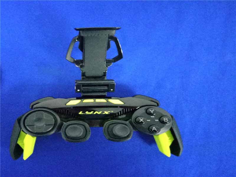
P25SS32269A
Aug 31, 2015Mad Catz L.Y.N.X.3 Mobile Wireless Controller
Equipment Class
DSS - Part 15 Spread Spectrum Transmitter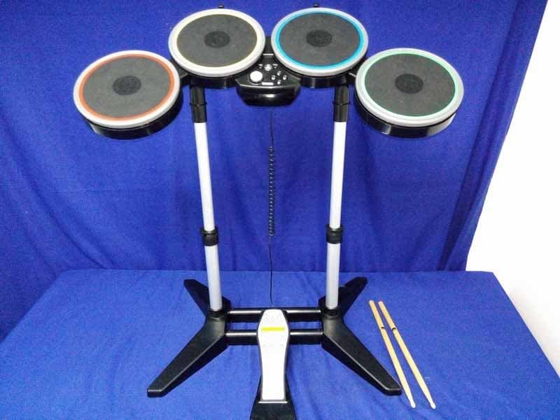
P25M991262A
Jun 24, 2015Rock Band 4 Wireless Drum Set for PlayStation 4
Equipment Class
DSS - Part 15 Spread Spectrum Transmitter
P25M991261A
Jun 02, 2015Rock Band 4 Wireless Fender Stratocasterfor PlayStation 4
Equipment Class
DSS - Part 15 Spread Spectrum Transmitter
P25SS32272A
Apr 25, 2015Mad Catz S.U.R.F.R
Equipment Class
DSS - Part 15 Spread Spectrum Transmitter
P25R232267A
Mar 03, 2015L.Y.N.X.9 Mobile Hybrid Controller
Equipment Class
DSS - Part 15 Spread Spectrum Transmitter