P29-RFMODEMCR012RF modem which transmits/receives data between veh
E-Drive Technology Ltd.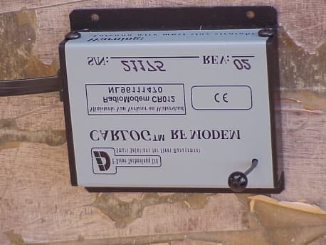
Click to zoom
Application Details
- Equipment Class
- DSR - Part 15 Remote Control/Security Device Transceiver
- Date of Grant
- Aug 25, 2002
- Application Purpose
- Original Equipment
- Date of Application
- Dec 11, 2001
- Equipment Note
- RF modem which transmits/receives data between veh
- Frequency Range
- 433.92000000 - 433.92000000
- Company
- E-Drive Technology Ltd.
- Country
- Israel
Documents & Files
Document Text
Text extracted from the exhibit documents filed with the FCC. Open a document above to read the original.
Users Manual
RF Receiving Station – For Windows Installing the software: 1. Insert ‘Disk1’ Choose ‘Start’ and ‘Run’ and run ‘Setup.exe’. Follow the installation steps and complete the installation by using the default parameters or enter different parameters to install the software in a different location. 2. To run the software. Make sure to connect the RF Modem unit to one of the PC COM Ports and plug the power supply to the RF Modem. Choose ‘Run’, ‘Program Files’ and run the ‘WRFLog’ application. Using the software: 1. When running the software it will try to identify the RF Modem unit. On a success configuration you will get a blue or green eye on the screen. On fail you will get an Error message and a red eye on the screen. ‘Main’ Application form: • The eye picture: Blue – Searching for vehicles and no new files to import. Green – Searching for vehicles and there are new files to import. Red – Can’t get the RF Modem unit ID and not searching for vehicles. • Upper message line - The program status messages. • Unprocessed Files - Number of new files in the INPUT directory. • Last received vehicles window - Show the last received vehicles ID number and the receiving date and time. • ‘Disable / Enable’ button -To stop / start the receiving process from vehicles. • ‘Minimize’ button -To minimize the window into the Start bar. • ‘Options’ button - Open the Option form to change the configuration setup. • ‘Report’ button - Show report for all the receiving vehicles in this station that includes date, time, last vehicle odometer and if the vehicle odometer is not running. • ‘Exit’ - Quit the application. 2. To change the software configuration setup. Choose ‘Options’ and enter the following configuration: ‘Options’ application form: • Port Number - The COM Port number where the RF Modem unit is connected to the PC. • Net Number - The RF Network number for the Vehicles receiving station. • RF Sensor connected - If the RF Modem unit is connected to an external sensor to be activate, check this box else live it empty (Default). • Update time & date - The application can update the Vehicles clock every given day(s) by the RF Modem. • Send update’s - To send Permission codes updates to the vehicles by the RF Modem. • Main Data files path - The main directory where you want the Input files to be saved after downloading from the vehicles. Under this directory the application will create directories for each type of downloading files (INPUT, LAST5MIN, FUELLOG...). • Create Data files for local computer - This option will save the downloaded data in the current computer for local use. • Create Data files for Remote computer - This will save the downloaded files for transferring them to another Host computer. 3. This application can run in the background. It means that if you received new vehicles data you can run the Database application and process the input files while this application continues to run.
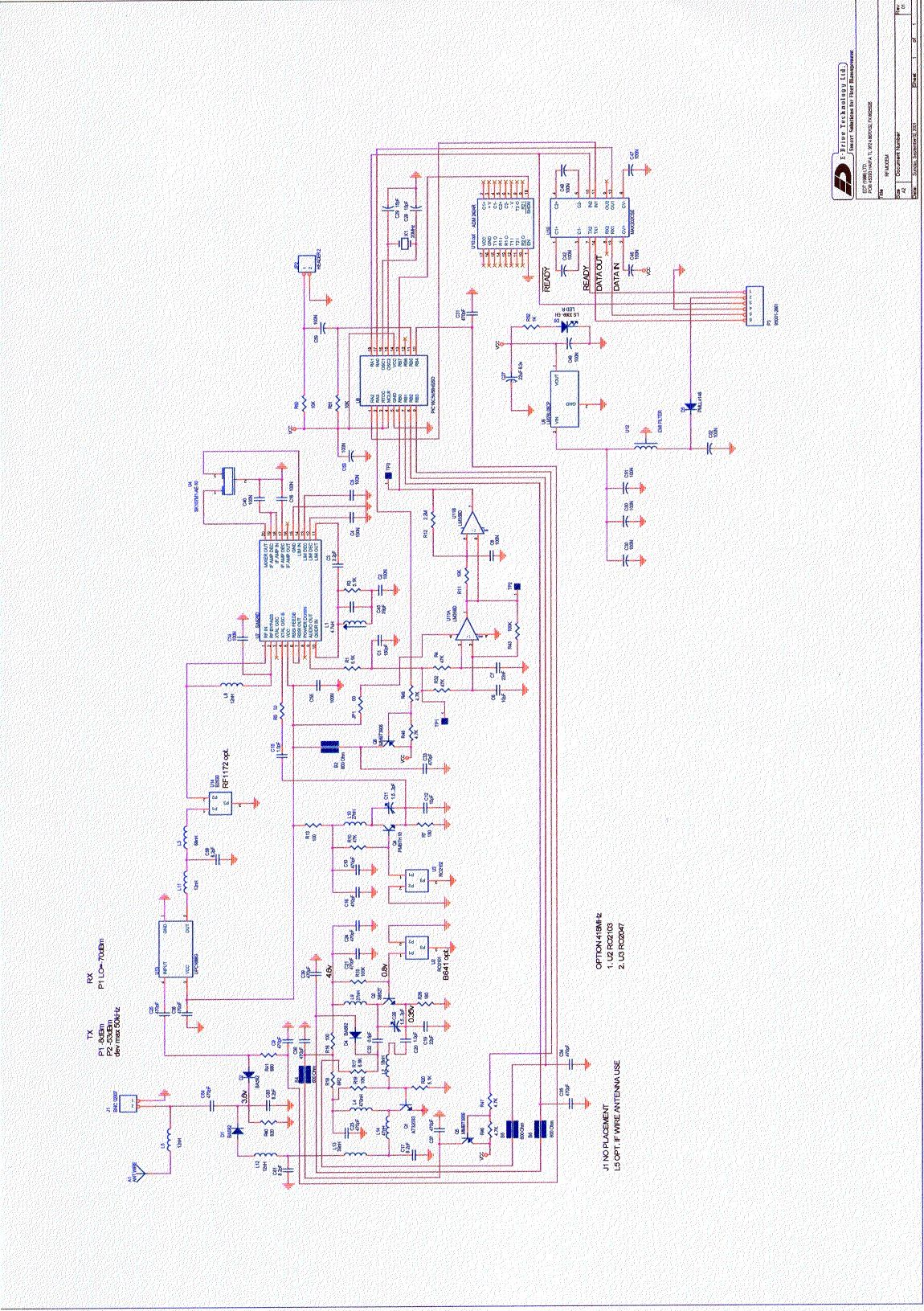
Block Diagram
18 KEREN HAYSOD St., TIRAT HACARMEL 39120, ISRAEL Tel: 972 4 8577870, Fax: 972 4 8580 566 internet : [email protected] RF modem unit • •• • Block Diagram : Controller + Software Resonator 433.92 MHz Matching Circuit Antenna Power Switch
External Photos
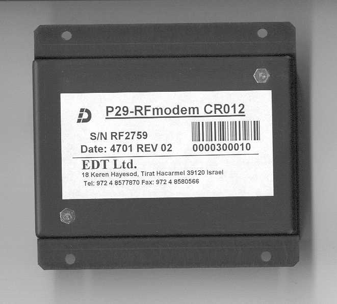
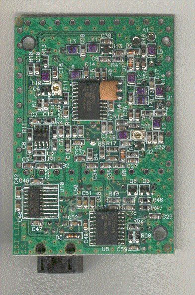
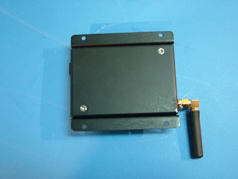
P29-RFmodem CR012 External photos
ID Label/Location Info
RF modem CR012 identification label and location info Figure 1: Identification label Figure 2: The identification label is attached to the back panel of the RF modem
ID Label/Location Info
RF modem CR012 identification label and location info Figure 1: The Identification label Figure 2: The identification label attached to the back panel of the RF modem
ID Label/Location Info
RF modem CR012 identification label and location info Figure 1: The Identification label Figure 2: The identification label attached to the back panel of the RF modem
Operational Description
18 KEREN HAYSOD St., TIRAT HACARMEL 39120, ISRAEL Tel: 972 4 8577870, Fax: 972 4 8580 566 internet : [email protected] RF modem unit – Operational Description The CR012 RF modem is capable of transmitting data between two or more vehicles or Fuel stations. Unique ID code allows more than 300 units to be networked at the same time. The less than 1 mW transmission power makes it very safe to use on every environment. Technical Data: • •• • Freq. 433.92 MHz • •• • Modulation FSK (F3B) • •• • Deviation 100 KHz pp. • •• • Sensitivity -100dBm. • •• • Signal to noise 12 dB. • •• • Range 150 meters (Free space radius) • •• • Antenna Schot • •• • Half duplex transmission with data compression. • •• • Baud rate 9,600 BPS. from host to unit and 5,000 BPS on air. • •• • Protocol RS232 • •• • Handshaking method by busy signal TTL / Cmos Levels • •• • Unique Burned ld. # code for networking usage. • •• • DSP. For a very low signal to noise ratio. • •• • Operating voltage : 8-19 volt. • •• • Current consumption: • •• • Transmission: 48 mA. • •• • Receiving: 30 mA. • •• • Stand by :(Sleep) 15 mA. • •• • Weight: 85 gr. (Without cables) • •• • Dimension: 82 x 85 x 27 mm. • •• • Telephone 6 pins communication connector. • •• • Operating Temperature range - 40 to + 80 Deg. • •• • SMT component technology. • •• • Packed in an aluminum black chassis.
Operational Description
TO:Mr. Steve Dayhoff, FCC Application Processing Branch FROM:Yuri Rozenberg, Head of EMC Lab, The Standards Institution of Israel RE:FCC ID: P29-RFMODEMCR012; Applicant name: E-Drive Technology Ltd. Correspondence Reference Number: 23740 731 Confirmation Number: EA523087 Subject:Dismissal of Application Dear Mr. Steve Dayhoff, Basing on the technical description provided by our customer E-Drive Technology Ltd we have concluded that the RF Modem falls into the scope of 15.231 (a), and not 15.231 (e). The way of operation is described bellow: Upon the return of the vehicle to its base parking lot, a trigger is manually sent by the "receiving" unit to the receiving part of the modem in the vehicle, the vehicle would then respond to the command by sending back its vehicle license ID together with the driver ID number a total length of up to 20 digits. (the air baud is about 5,000 BPS, meaning that whole transmission should take about 50 msec.). The vehicle may return to its parking once a day, so the transceiver work should be considered as NON PERIODICALLY. The RF modem transmits the recognition codes only and not data as permitted for NON PERIODIC operation according to 15.231 (a). We hope you will a gree with our reasons. Best Regards Yuri Rozenberg
Operational Description
TO:Mr. Steve Dayhoff, FCC Application Processing Branch FROM:Yuri Rozenberg, Head of EMC Lab, The Standards Institution of Israel RE:FCC ID: P29-RFMODEMCR012; Applicant name: E-Drive Technology Ltd. Correspondence Reference Number: 23740 731 Confirmation Number: EA523087 Subject:Dismissal of Application Dear Mr. Steve Dayhoff, Basing on the technical description provided by our customer E-Drive Technology Ltd we have concluded that the RF Modem falls into the scope of 15.231 (a), and not 15.231 (e). The way of operation is described bellow: Upon the return of the vehicle to its base parking lot, a trigger is manually sent by the "receiving" unit to the receiving part of the modem in the vehicle, the vehicle would then respond to the command by sending back its vehicle license ID together with the driver ID number a total length of up to 20 digits. (the air baud is about 5,000 BPS, meaning that whole transmission should take about 50 msec.). The vehicle may return to its parking once a day, so the transceiver work should be considered as NON PERIODICALLY. The RF modem transmits the recognition codes only and not data as permitted for NON PERIODIC operation according to 15.231 (a). We hope you will a gree with our reasons. Best Regards Yuri Rozenberg
Test Report
Test Report No.8112319723 For E-Drive Technology Ltd. Equipment Under Test: RF Modem Model: CR012 From The Standards Institution Of Israel Industry Division Telematics Laboratory EMC Section Certificate No.1487-01 Test Report No.: 8112319723Page 1 of 28 Pages T itle: T est on RF ModemModel: CR012 Order placed by:E-Drive Techno logy Ltd. Address:18 Keren Hayesod Str., P.O.B. 2035 Tirat-Hacarmel 39120 Israel Sample for test selected by:The orderer T he date of test:20/11, 25/11/2001. Description of Equipment Under T est (EUT ):RF Modem Model:CR012 Manufactured by:E-Drive Techno logy Ltd. Reference Documents: ! CFR 47 FCC: “Rules and Regulations”; Part 15. “Radio frequency devices”; Subpart B: Unintentional radiators Sec.15.109 Subpart C: Intentio nal radiators. Sec. 15.205, 15.207, 15.209,15.231 Test Results:The EUT was found to be in compliance with the requirements of FCC Rules Part 15 Subpart B Sec. 15.109 Subpart C Sec. 15.205, 15.207, 15.209, 15.231. This Test Report contains 28 pages and may be used only in full. This Test Report applies only to the specimen tested and may not be applied to other specimens of the same product. Test Report No.: 8112319723Page 2 of 28 Pages T itle: T est on RF ModemModel: CR012 Table of Contents EUT Description and operation__________________________________________________ 3 1.1General description: __________________________________________________________ 3 1.2Auxiliary equipment used: _____________________________________________________ 4 1.3EUT setup and operation: _____________________________________________________ 5 Test specification, Methods and Procedures ________________________________________ 6 Measurements, examinations and derived results ___________________________________ 6 3.1Location of the Test Site: ______________________________________________________ 6 3.2Test condition: _______________________________________________________________ 6 3.3Conducted emission test (Subpart C clause 15.207):________________________________ 7 3.4Radiated emission test (Subpart C clause 15.231 (b)) _______________________________ 9 3.5Bandwidth measurements (Subpart C clause 15.231 (c) ) : _________________________ 15 3.6Radiated emission test (Subpart B clause 15.109): ________________________________ 16 Compliance with specification __________________________________________________ 18 Appendix 1: Test equipment used _______________________________________________ 19 Appendix 2: Antenna Factor and Cable Loss ______________________________________ 20 Appendix 3: Test configuration illustration _______________________________________ 23 Test Report No.: 8112319723Page 3 of 28 Pages T itle: T est on RF ModemModel: CR012 1 EUT Description and operation 1.1 General description: Description of Equipment Under T est (EUT ): RF Modem Model:CR012 Manufactured by:E-Drive Techno logy Ltd. The EUT is an RF Modem used in security and automatically fuel systems. The EUT is capable of transmitting/receiving data between two or more vehicles or fuel statio ns. Unique ID code allows more than 300 units to be networked at the same time. The EUT’s technical parameters are : Operating frequency 433.92 MHz. Type of modulation usedFSK (F3B) Transmission power < 1 mW Interface RS 232 Operating voltage:12 VDC. • Dimensions: 82 x 85 x 27 mm approx. • The EUT is powered by 12 VDC from the external power adapter. The po wer adapter is connected to PC thro ugh the special connector which provides the power and RS 232 interface to EUT. 1.2 EUT's sub-assemblies list: 1. RF Modem, contains o ne PCB Motherboard P/N RS2 PCB 0220-0053 2. External power adapter mfr NEGBA 110 VAC/12 VDC. Test Report No.: 8112319723Page 4 of 28 Pages T itle: T est on RF ModemModel: CR012 1.3 EUT connectors diagram: 1.4 Auxiliary equipment used: The auxiliary equipment used is detailed in Table 2. Table 2. Auxiliary equipment used NameMFRModelSer. No./FCC ID PC computerIBMMachine type:6275-M20S/N 559B704 MonitorIBM6547-OBNS/N -55-DAA62 PrinterHPDeslJet 895 CxiS/N ES93Q2COV8 MouseMade for IBM by Logitech M-S34S/N 23-171774 FCC ID: DZL 211029 KeyboradIBMKB-7953S/N 2009 RF MODEM POWER ADAPTER special PC connector RJ 45 RS 232 interface unshielded cable 1 m length standard power outlet standard power jack 12 VC RS 232 110 VAC mains Test Report No.: 8112319723Page 5 of 28 Pages T itle: T est on RF ModemModel: CR012 1.5 EUT setup and operation: For testing purposes the EUT was connected to PC computer through RS232 interface and operated using the customer software. The test setup is shown in Figure 1. The EUT was tested with typical modulatio n applied. Figure 1. EUT test setup Printer Keyboard Mous e 230 VAC PC RS 232 , cable 1 m lengt Monitor EUT RF Modem CR01 110VAC/ 12 VDC Power Adapter 110 VAC mains Test Report No.: 8112319723Page 6 of 28 Pages T itle: T est on RF ModemModel: CR012 2 Test specification, Methods and Procedures Test Specification: ! CFR 47 FCC: “Rules and Regulations”; Part 15. “Radio frequency devices”; Subpart B: Unintentional radiators Subpart C: Intentio nal radiators. Methods and Procedures: ! ANSI C63/4/1992:"American National Standard for Methods of Measurement of Radio- Noise Emissions from Low-Voltage Electrical and Electronic Equipment in the range of 9 kHz to 40 GHz”. 3 Measurements, examinations and derived results 3.1 Location of the Test Site: EMC laboratory of the Standards Institutio n of Israel, Tel-Aviv. Open Area Test Site located at Kibbutz Native Halamed Hai in Emek HaEla, Israel. 3.2 Test condition: Temperature: 22 °C Humidity:60 % Test Report No.: 8112319723Page 7 of 28 Pages T itle: T est on RF ModemModel: CR012 3.3 Conducted emission test (Subpart C clause 15.207): 3.3.1 Test Configuration: The measurements were performed on the mains input of the EUT power adapter. The EUT connected to PC via RS232 was placed on a non-metallic table in a shielded chamber at a height of 80 cm from the floor of the shielded chamber and 40 cm from the wall of the shielded chamber…
Text truncated - open the document above for the full version.
Test Setup Photos
P29-RFmodem CR012 Test setup photos Open field test site Radiated emission test setup Open field test site Radiated emission test setup
Contact Information
Applicant
Amir Badian(Managing Director)
Technical Contact
E-Drive Technology Ltd.Eyal David
[email protected]+972-4-8577870
18 Keren Hayesod St. · Tirat Hacarmel · Israel
Non-Technical Contact
E-Drive Technology Ltd.Eyal David
[email protected]+972-4-8577870
Test Firm
The Standards Institution of IsraelYuri Rozenberg
Technical Specifications
| # | Rule Parts | Frequency Range | Power Output |
|---|---|---|---|
| 1 | 15C | 433.92 MHz - 433.92 MHz | - |
Other Applications from E-Drive Technology Ltd.
P29EDT88RFM20707
Dec 27, 2007Wireless Data Logger
Equipment Class
DSC - Part 15 Security/Remote Control Transmitter