P29EDT88RFM20707Wireless Data Logger
E-Drive Technology Ltd.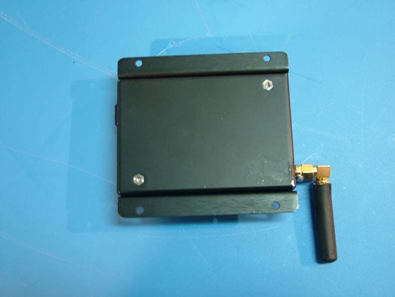
Click to zoom
Application Details
- Equipment Class
- DSC - Part 15 Security/Remote Control Transmitter
- Date of Grant
- Dec 27, 2007
- Application Purpose
- Original Equipment
- Date of Application
- Dec 26, 2007
- Equipment Note
- Wireless Data Logger
- Frequency Range
- 433.93000000 - 433.93000000
- Company
- E-Drive Technology Ltd.
- Country
- Israel
Documents & Files
Document Text
Text extracted from the exhibit documents filed with the FCC. Open a document above to read the original.
Users Manual
1 Keren Hayesod St. 15 P.O.B 2035 Tirat Hacarmel 39120, ISRAEL Tel: +972 4 8577 870 Fax: + 972 4 8580 566 Web: www.e-drivetech.com 2 Keren Hayesod St. 15 P.O.B 2035 Tirat Hacarmel 39120, ISRAEL Tel: +972 4 8577 870 Fax: + 972 4 8580 566 Web: www.e-drivetech.com This device complies with Part 15 of the FCC Rules. Operation is subject to the following two conditions: (1) this device may not cause harmful interference, (2) this device must accept any interference received, including interference that may cause undesired operation. Warnings: This equipment has been approved for mobile applications where the equipment should be used at distances greater than 20cm from the human body (with the exception of hands, wrists, feet and ankles). Operation at distances less than 20 cm is strictly prohibited. Changes or modifications not expressly approved by the party responsible for compliance could void the user's authority to operate the equipment. The antenna(s) used for this transmitter must not be co-located or operating in conjunction with any other antenna or transmitter. 3 Keren Hayesod St. 15 P.O.B 2035 Tirat Hacarmel 39120, ISRAEL Tel: +972 4 8577 870 Fax: + 972 4 8580 566 Web: www.e-drivetech.com 1) This device may be used only as a part of RF Receiving Station. 2) Communicate this device accordingly with the communication chart below using only original communication cable. Communication in any other ways is strictly forbidden. 3) Power (8-20VDC) should be supplied only by approved power supply complying with limited power source requirements of EN60950-1. 4) This device should be used at distances greater than 20cm from the human body. 5) Don’t touch the device RF antenna to any other subject when being in use. 6) Don’t use the device in water and dust environment. 7) Avoid blows, drops and mechanical shocks. 4 Keren Hayesod St. 15 P.O.B 2035 Tirat Hacarmel 39120, ISRAEL Tel: +972 4 8577 870 Fax: + 972 4 8580 566 Web: www.e-drivetech.com 28/12/2006 RF Specification: • RF Transmitter/Receiver Frequency 433.92 MHz • Frequency separation 9.9kHz • Data Rate 4.8kBaud • Data Format NRZ (Non-Return-to-Zero) • RF Output Power -25dBm • Channel Spacing 25kHz • Modulation FSK (Frequency-Shift- -Keying) • RSSI -146dBm • Outdoor Transmit/Receive Range Up to 1000 feet RF-Antenna type used with RF-Modem connected to: • RF-Receiving Station on PC Indoor/ Strait-Right Angle Gain 2.15dB, TLB-433-JW-5L Without cable 5 Keren Hayesod St. 15 P.O.B 2035 Tirat Hacarmel 39120, ISRAEL Tel: +972 4 8577 870 Fax: + 972 4 8580 566 Web: www.e-drivetech.com Power Supply • Power Supply 8-20VDC • Power Current 100mA max • Protect inverted power supply Interface Connection: • RS232 Communication Indication: • Transmit /Tx RED LED • Receive /Rx GREEN LED Physical Specifications • Construction Metal Case Black • Dimensions 200x110x100mm With RF-Antenna • Weight 100g With RF-Antenna Environment Condition • Operation Temperature -20 To +55C • Storage Temperature -40 To +85C 6 Keren Hayesod St. 15 P.O.B 2035 Tirat Hacarmel 39120, ISRAEL Tel: +972 4 8577 870 Fax: + 972 4 8580 566 Web: www.e-drivetech.com The RF-Modem II is a low-cost wireless modem that operates in the license-free 433.92 MHz ISM frequency band range. The RF-Modem II transfers data up to 1,000 feet. Its small size and other unique features, such as low power consumption, make RF-Modem II the ideal as high performance RF data transceiver. RF-Modem II can be connected and fully operated from the PC by means of RF Receiving Station. 7 Keren Hayesod St. 15 P.O.B 2035 Tirat Hacarmel 39120, ISRAEL Tel: +972 4 8577 870 Fax: + 972 4 8580 566 Web: www.e-drivetech.com 1. RF-Modem II Communication Connector J1 MicroFit 2*3 Pins Male Name Pin Description Note TxD_MODEM 1 Data Output RS232 RxD_MODEM 2 Data Input RS232 GND 3 Ground GND RF_REQ 4 Logic Output Open Collector Main_12V 5 Main Power Power N/C 6 RF-Modem II RF-Antenna Connector J3 SMA Female Name Pin Description Note RF Data 1 RF Output/Input 433.92MHz GND 2/3/4/5 Ground GND 8 Keren Hayesod St. 15 P.O.B 2035 Tirat Hacarmel 39120, ISRAEL Tel: +972 4 8577 870 Fax: + 972 4 8580 566 Web: www.e-drivetech.com RF Receiving Station on PC COM Port1 Modem Cable Modem Cable RF Antenna Communication Connector J1 Communication Connector J1 Transmit/Receive J1 J2 J3 J4 J5 J7 RF-Modem II RF-Modem II RF-Antenna RF stand alone Station 9 Keren Hayesod St. 15 P.O.B 2035 Tirat Hacarmel 39120, ISRAEL Tel: +972 4 8577 870 Fax: + 972 4 8580 566 Web: www.e-drivetech.com
Cover Letter(s)
1 Keren Hayesod St. 15 P.O.B 2035 Tirat Hacarmel 39120, ISRAEL Tel: +972 4 8577 870 Fax: + 972 4 8580 566 Web: www.e-drivetech.com Antenna Parameters • Frequency Range (MHz): 433+/-5 • V.S.W.R: ≤ 1.5 • Input Impedance (Ω): 50 • Max. Power (W): 10 • Gain (dBi): 2.15 • Polarization: Vertical • Weight (g): 15 • Height (mm): 47 • Cable Length: None • Color: Black Antenna connection method RF antenna is connected to the PCB-mounted SMA connector by soldering. This way antenna can not be replaced or removed from RF-Modem II unit according with requirements of FCC Rules /Section 15.203/. Before soldering antenna screw surface is opened by 45-degree cutting as shown below
Cover Letter(s)
American Telecommunications Certification Body Inc. 6731 Whittier Ave, McLean, VA 22101 November 13, 2007 RE: ATCB005616 FCC ID: P29EDT88RFM20707 for E-Drive Technology, Ltd. I have a few comments on this Application. Depending on your responses, kindly understand there may be additional comments. 1. Please confirm whether or not modular approval is being sought for this transmitter. If it is, a cover letter must be submitted describing how it meets the 8 conditions necessary for modular transmitter approval contained in FCC Public Notice DA1407-2000 (copy attached). If it doesn’t meet all these conditions, it still may be eligible for Limited Modular Approval (LMA), but you need to request it in the cover letter. 2. Please provide justification for not providing AC line conducted emission measurements showing compliance with Section 15.207 of the FCC Rules especially if you are seeking modular or LMA approval of this transmitter or provide these measurements. Information indicates it operates on 12 VDC but it also connects to a personal computer so it is not always used on-board a vehicle or strictly powered by a battery. 3. Please provide justification for keeping the user guide confidential. Normally user manuals or guides are provided with every product sold. The submitted user guide does not look like it contains confidential information. 4. Please provide test setup photos of the radiated emissions tests as required by Sections 11.6.2 and 10.1.12 of ANSI C63.4 2003. The FCC considers this a requirement for all Part 15 transmitter approvals. 5. Please provide a letter from Eyal David, the Grantee Code contact person for E-Drive Technology on the FCC Website, giving Amir Badian permission to represent E-Drive Technology before the FCC. Alternatively, Amir Badian may be listed as the contact person on the FCC Website by having the FCC Website updated. For help updating the FCC Website, please contact Ms. Marianne Bosley of ATCB by email at [email protected]. 6. The internal and external photos of this device show a different antenna than is shown in the rest of the supporting documentation (antenna information exhibit, label location exhibit, operational description exhibit and user guide exhibit). Please address this discrepancy by replacing the incorrect exhibits. 7. Please describe how soldering the antenna to the external antenna connector on the device meets the antenna requirement of Section 15.203 of the FCC Rules. 8. Please confirm that the radiated emission levels were maximized as specified in Section 13.1.4.1 of C63.4 by: (1) testing the transmitter in 3 orthogonal axes and (2) adjusting the transmit antenna in different orientations during these tests. 9. For Your Information – The test report is lacking several important items which the FCC looks for when reviewing measurement results. The range over which radiated emission measurements were performed. The polarity and height of the receive antenna that produces the worst case results is not indicated in the test results. The orthogonal axis orientation of the Page 2 November 13, 2007 transmitter is not indicated in the test results. There is no calculation showing all the correction factors used in determining the final field strength of the strongest emission (e.g., antenna gain, cable loss, amplifier gain, etc.). Please revise your test results to indicate these items in future test reports. Richard Fabina Examining Engineer mailto: [email protected] The items indicated above must be submitted before processing can continue on the above referenced application. Failure to provide the requested information may result in application termination. Correspondence should be considered part of the permanent submission and may be viewed from the Internet after a Grant of Equipment Authorization is issued. Please do not respond to this correspondence using the email reply button. In order for your response to be processed expeditiously, you must submit your documents through the AmericanTCB.com website. Also, please note that partial responses increase processing time and should not be submitted. Any questions about the content of this correspondence should be directed to the sender.
Cover Letter(s)
Multiple files are bound together in this PDF Package. Adobe recommends using Adobe Reader or Adobe Acrobat version 8 or later to work with documents contained within a PDF Package. By updating to the latest version, you’ll enjoy the following benefits: • Efficient, integrated PDF viewing • Easy printing • Quick searches Don’t have the latest version of Adobe Reader? Click here to download the latest version of Adobe Reader If you already have Adobe Reader 8, click a file in this PDF Package to view it.
External Photos
Top View Bottom View
Internal Photos
Top View Bottom View, w/ RF Shielding Bottom View, RF Shielding removed Antenna Connection
Operational Description
1 Keren Hayesod St. 15 P.O.B 2035 Tirat Hacarmel 39120, ISRAEL Tel: +972 4 8577 870 Fax: + 972 4 8580 566 Web: www.e-drivetech.com 2 Keren Hayesod St. 15 P.O.B 2035 Tirat Hacarmel 39120, ISRAEL Tel: +972 4 8577 870 Fax: + 972 4 8580 566 Web: www.e-drivetech.com Applications The RF-Modem-II is used as 433MHz transceiver for wireless communications data logger and control systems. The System operates on radio frequency communication between the systems RF Stand alone Control Unit and the Management PC. The unit transmits digital (control and information) data to the main data logger pc. 3 Keren Hayesod St. 15 P.O.B 2035 Tirat Hacarmel 39120, ISRAEL Tel: +972 4 8577 870 Fax: + 972 4 8580 566 Web: www.e-drivetech.co m Principles of Operation The RF-Modem-II is based on Texas Instruments CC1020 UHF transceiver with TI recommended external passive RF components. CC1020 is a true single-chip UHF transceiver designed for very low power and very low voltage wireless applications and suited for narrow-band systems. The RF-Modem-II includes CC1020 together with a Microchip’s MCU like PIC18F2420 which provides CC1020 programming and data exchange between transceiver and microcontroller. At the other hand, MCU provides RS232 Communications between RF-Modem-II and external units like Management PC and other source unit. RF-Modem-II block Diagram. RF Section Digital Section RF Transceiver CC1020 MCU PIC18F2420 Power Module 12VDC/5VDC Tx/Rx Indication PDI PCLK PDO DIO DCLK Power Module 5VDC/3VDC 12VDC3VDC5VDC 4.8KHz 433.92MHzPSEL 4.8KHz 4.8KHz 4.8KHz 4.8KHz RS232 Transmitter/ Receiver 4.8KHz 4.8KHz 4.8KHz 4 Keren Hayesod St. 15 P.O.B 2035 Tirat Hacarmel 39120, ISRAEL Tel: +972 4 8577 870 Fax: + 972 4 8580 566 Web: www.e-drivetech.com RF Circuit Description CC1020 UHF transceiver includes a low-IF receiver. The received RF signal is amplified by the low-noise amplifier (LNA and LNA2) and down-converted in quadrature (I and Q) to the intermediate frequency (IF). At IF, the I/O signal is complex filtered and amplified, and then digitized by the ADCs. Automatic gain control, fine channel filtering, demodulation and bit synchronization is performed digitally. CC1020 outputs the digital demodulated data on the DIO pin. A synchronized data clock is available at the DCLK pin. RSSI is available in digital format and can be read via the serial interface. The RSSI also features a programmable carrier sense indicator. In transmit mode, the synthesized RF frequency is fed directly to the power amplifier (PA). The RF output is frequency shift keyed (FSK) by the digital bit stream that is fed to the DIO pin. The frequency synthesizer includes a completely on-chip LC VCO and a 90 degrees phase splitter for generating the LO_I and LO_Q signals to the down-conversion mixers in receive mode. The CHP_OUT pin is the charge pump output and VC is the control node of the on-chip VCO. The external loop filter is placed between these pins. A crystal is to be connected between XOSC_Q1 and XOSC_Q2. A lock signal is available from the PLL. 5 Keren Hayesod St. 15 P.O.B 2035 Tirat Hacarmel 39120, ISRAEL Tel: +972 4 8577 870 Fax: + 972 4 8580 566 Web: www.e-drivetech.com Microcontroller Interface CC1020 interfaces to a microcontroller through two serial interfaces. Using ones microcontroller is able to: • Program CC020 into different modes via the 4-wire serial configuration interface (PDI, PDO, PCLK and PSEL) • Interface to the bi-directional synchronous data signal interface (DIO and DCLK) • Optionally, the microcontroller can do data encoding / decoding • Optionally, the microcontroller can monitor the LOCK pin for frequency lock status, carrier sense status or other status information. • Optionally, the microcontroller can read back the digital RSSI value and other status information via the 4-wire serial interface The microcontroller uses 3 or 4 I/O pins for the configuration interface (PDI, PDO, PCLK and PSEL). PDO should be connected to a microcontroller input. PDI, PCLK and PSEL must be microcontroller outputs. One I/O pin can be saved if PDI and PDO are connected together and a bi-directional pin is used at the microcontroller. The microcontroller interface is shown below. 6 Keren Hayesod St. 15 P.O.B 2035 Tirat Hacarmel 39120, ISRAEL Tel: +972 4 8577 870 Fax: + 972 4 8580 566 Web: www.e-drivetech.co m Embedded and PC Software Stand alone unit with embedded software is used for data monitoring, recording and downloading to the RF-Modem-II unit on the Stand alone side for the further transmitting to the Management PC. At the other hand, Management PC with software called “PC Receiving Station” is used for data receiving from the RF-Modem-II unit on the PC side. Then data received this way is used for global data monitoring, processing, billing and system analysis for Management purposes. Embedded stand alone and PC software allows setting the modem parameter such as: type of operation, receiving/transmitting digital data with FSK (Frequency Shift Keying), modulation and NRZ (Non-Return-to-Zero) Data format. Communication data rate is 4,8kBaud, duration of each transmission and silent period between each transmission. The transmission duration and silent periods are limited to be less than 1 second and 30 sec correspondingly 7 Keren Hayesod St. 15 P.O.B 2035 Tirat Hacarmel 39120, ISRAEL Tel: +972 4 8577 870 Fax: + 972 4 8580 566 Web: www.e-drivetech.com Configuration Overview CC1020 is configured to achieve optimum performance. Through the programmable configuration registers the following key parameters are programmed: • Receive / transmit mode • RF output power • Frequency synthesizer key parameters: RF output frequency, FSK frequency separation, crystal oscillator reference frequency • Power-down / power-up mode • Crystal oscillator power-up / power-down • Data rate and data format (NRZ, Manchester coded or UART interface) • Synthesizer lock indicator mode • Digital RSSI and carrier sense • FSK / GFSK / OOK modulation 8 Kere…
Text truncated - open the document above for the full version.
Test Report
E E E l l l e e e c c c t t t r r r o o o m m m a a a g g g n n n e e e t t t i i i c c c C C C o o o m m m p p p a a a t t t i i i b b b i i i l l l i i i t t t y y y T T T e e e s s s t t t R R R e e e p p p o o o r r r t t t T T T e e e s s s t t t R R R e e e p p p o o o r r r t t t N N N o o o : : : M M M L L L M M M 0 0 0 9 9 9 0 0 0 7 7 7 0 0 0 7 7 7 Issued on: July 09, 2007 P P P r r r o o o d d d u u u c c c t t t N N N a a a m m m e e e R R R F F F - - - M M M o o o d d d e e e m m m I I I I I I M M M o o o d d d e e e l l l : : : C C C R R R 0 0 0 1 1 1 1 1 1 - - - 2 2 2 0 0 0 0 0 0 7 7 7 F F F C C C C C C I I I D D D : : : P P P 2 2 2 9 9 9 E E E D D D T T T 8 8 8 8 8 8 R R R F F F M M M 2 2 2 0 0 0 7 7 7 0 0 0 7 7 7 T T T e e e s s s t t t e e e d d d A A A c c c c c c o o o r r r d d d i i i n n n g g g t t t o o o F F F C C C C C C 4 4 4 7 7 7 C C C F F F R R R , , , P P P a a a r r r t t t 1 1 1 5 5 5 . . . 2 2 2 3 3 3 1 1 1 ( ( ( e e e ) ) ) T T T e e e s s s t t t s s s P P P e e e r r r f f f o o o r r r m m m e e e d d d f f f o o o r r r E E E - - - D D D r r r i i i v v v e e e T T T e e e c c c h h h n n n o o o l l l o o o g g g y y y L L L t t t d d d . . . 18 Keren Hayesod Street, P.O.Box 2035, Tirat-Hacarmel 39120, Israel Tel: +972-4-8100755 Q Q Q u u u a a a l l l i i i T T T e e e c c c h h h E E E M M M C C C L L L a a a b b b o o o r r r a a a t t t o o o r r r y y y 30 Hasivim Street, Petah-Tikva, 49517, Israel Tel: +972-3-926 8443 Fax: +972-3-928 7490 1633.01 Test Report: MLM 090707 Date: 09.07.2007 Rev. 1 E-Drive Technology Ltd. Page 2 of 28 RF Modem EMC Lab The information contained herein is the property of QualiTech, EMC Lab and is supplied without liability for errors or omissions. The copyright for this document vests in QualiTech, EMC Lab. All rights reserved. This Test Report may not be reproduced, by any method, without the written permission of the QualiTech, EMC Lab. If and when such permission is granted, the report must be reproduced only in the full format. T T T e e e s s s t t t p p p e e e r r r s s s o o o n n n n n n e e e l l l Tests Performed By: ----------------------------------------- Rami Nataf Ilya Arbitman Report Prepared By: ----------------------------------------- Bina Talkar Report Reviewed By: ----------------------------------------- Y. Zucker QA and Lab. Manager QualiTech EMC Laboratory 1633.01 Test Report: MLM 090707 Date: 09.07.2007 Rev. 1 E-Drive Technology Ltd. Page 3 of 28 RF Modem EMC Lab A A A c c c c c c r r r e e e d d d i i i t t t a a a t t t i i i o o o n n n / / / R R R e e e g g g i i i s s s t t t r r r a a a t t t i i i o o o n n n r r r e e e f f f e e e r r r e e e n n n c c c e e e & & & T T T e e e s s s t t t F F F a a a c c c i i i l l l i i i t t t y y y : : : Accreditation/ Registration reference: - A2LA Certificate Number: 1633.01 Test Facility description The tests were performed at the EMC Laboratory, QualiTech Division, ECI Telecom Group Address: 30, Hasivim St., Petah Tikva, Israel. Tel: 972-3-926-8443 T T T e e e s s s t t t R R R e e e p p p o o o r r r t t t d d d e e e t t t a a a i i i l l l s s s : : : Issued on: 09.07.2007 A A A s s s s s s e e e s s s s s s m m m e e e n n n t t t i i i n n n f f f o o o r r r m m m a a a t t t i i i o o o n n n : : : This report contains an assessment of the EUT against Electromagnetic Compatibility based upon tests carried out on the samples submitted. The results contained in this report relate only to the items tested. Manufactured products will not necessarily give identical results due to production and measurement tolerances. QualiTech, EMC Lab does not assume responsibility for any conclusion and generalization drawn from the test results with regards to other specimens or samples of type of the equipment represented by test item. The EUT was set up and exercised using the configuration, modes of operation and arrangements defined in this report only. M M M o o o d d d i i i f f f i i i c c c a a a t t t i i i o o o n n n s s s : : : Modifications made to the EUT None. Modifications made to the Test Standard None. Test Report: MLM 090707 Date: 09.07.2007 Rev. 1 E-Drive Technology Ltd. Page 4 of 28 RF Modem EMC Lab S S S u u u m m m m m m a a a r r r y y y o o o f f f C C C o o o m m m p p p l l l i i i a a a n n n c c c e e e S S S t t t a a a t t t u u u s s s Periodic operation in the band 40.66-40.70MHz and above 70MHz: FCC 47 CFR, Part 15.231(e) Test Spec. Clause Test Case Remarks §15.231(e) Field strength of fundamental, Radiated Pass §15.231(e) Field strength of the Spurious Emissions, Radiated Pass §15.205 Radiated Emissions, Restricted Bands Pass §15.231(c) Emission Bandwidth Pass §15.231(e) Duration of Transmission Pass §15.109 Radiated Emission (receive mode) Pass §15.107 Power Line Emission measurements Pass §15.203 Antenna Connector requirement Pass 1633.01 Test Report: MLM 090707 Date: 09.07.2007 Rev. 1 E-Drive Technology Ltd. Page 5 of 28 RF Modem EMC Lab T T T a a a b b b l l l e e e o o o f f f C C C o o o n n n t t t e e e n n n t t t 1. GENERAL DESCRIPTION................................................................................................................................................ 6 1.1. Description of the EUT /test Item:....................................................................................................6 2. METHOD OF MEASUREMENTS..................................................................................................................................... 6 2.1. Radiated Emissions Measurements in the restricted bands:.............................................................6 2.2. Radiated Field Strength and Emission BW Measurements:.............................................................6 2.3. Duration of Transmission, Emission BW, Conducted Measurement:..............................................6 2.4. Radiated Emission measurements:............................................…
Text truncated - open the document above for the full version.
Test Setup Photos
Applicant: E-Drive Technology Ltd. Test Setup Photographs Radiated Emission Testing Applicant: E-Drive Technology Ltd. Conducted Measurements Power Line Emission Measurements
Contact Information
Applicant
Amir Badian(Managing Director)
Technical Contact
E-Drive Technology Ltd.Alex Shekhtman
[email protected]972-77-7700466
Karen Hayesod St. 15 · Tirat Hacarmel · Israel
Non-Technical Contact
E-Drive Technology Ltd.Ilan Rubinoviz
[email protected]972-77-7700440
Test Firm
QualiTech EMC Laboratory (ECI Telecom)Yossi Zucker
Technical Specifications
| # | Rule Parts | Frequency Range | Power Output |
|---|---|---|---|
| 1 | 15.231(e) | 433.93 MHz - 433.93 MHz | - |
Other Applications from E-Drive Technology Ltd.
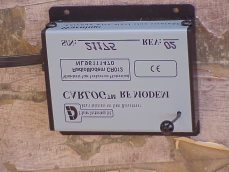
P29-RFMODEMCR012
Aug 25, 2002RF modem which transmits/receives data between veh
Equipment Class
DSR - Part 15 Remote Control/Security Device Transceiver