P2E01TPMS1Tire Pressure Transmitter
HCI Corporation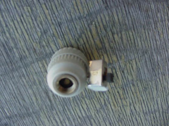
Click to zoom
Application Details
- Equipment Class
- DSC - Part 15 Security/Remote Control Transmitter
- Date of Grant
- Jan 24, 2002
- Application Purpose
- Original Equipment
- Date of Application
- Jan 24, 2002
- Equipment Note
- Tire Pressure Transmitter
- Frequency Range
- 433.92000000 - 433.92000000
- Company
- HCI Corporation
- Country
- United States
Documents & Files
Document Text
Text extracted from the exhibit documents filed with the FCC. Open a document above to read the original.
Users Manual
User’s Manual Tire Pressure Monitor TPM-S1/TPM-S2 TPM is one of the most advanced automobile tire pressure monitoring system. This system can automatically monitor your tires while you are driving your car. When any of the tire pressures fell under a safety level, the system will issue warning signals to notify you. The TPM can display individual tire pressures, which allows you to know your tire pressure situation at all time while you are driving. In addition, this system is very easy to install and very simple to operate. It enables you to always keep your tires properly inflated and, thereby, reduce your tire thread wears and prolong your tire lives. The best value TPM brings you is the peace of mind while driving, knowing that when you tires have problems, you will have advance warnings. 1 System Installation 1.1 System Parts Sensor Module Monitor Module Auxiliary Power Adapter DC power connector Connection cable 1.2 Sensor Module Installation The product package includes four long-life button battery packs, one for each sensor module. To install the battery: open the sensor module cap by hand, insert the battery pack into the battery compartment, then close the sensor module cap. Be sure to install the battery with the proper polarity allocation, and make sure not to touch the electronics inside the sensor module for it might affect system operations. On top of each sensor module cap there is a tire position mark, which: !"1R, indicates that it is for the right-front tire; !"2R, indicates that it is for the right-rear tire; !"1L, indicates that it is for the left-front tire; !"2L indicates that it is for the left-rear tire. !"2RI indicates that it is for the right-rear inner tire (6 tire option). !"2LI indicates that it is for the left-rear inner tire (6 tire option). Replace each tire valve stem cap with a sensor module and then tighten the sensor module by hand. Make sure the sensor module is installed to the correct tire that is corresponded to its position indicator. 1.3 Tire Pressure Monitor Installation Usually the monitor unit is placed on top of the dashboard, on the driver side near the windshield glass, with the display panel facing the driver. This way the power adaptor cable can run around the instrument panel and then go above or beneath the steering wheel, with the plug to be inserted into the cigarette lighter socket. The monitor unit can also be put inside the vehicle in any place that the user considered to be easily accessible. 2 How to Use the System 2.1 Monitor Module Display Panel Please see the display panel drawing. 2.2 Initial Situation Display In order to conserve the battery power inside the miniature sensor module, the sensor is shut down (i.e., not operational) when the automobile is stationary or when its speed is less than 15 miles per hour (mph). When the car speed reached 15 mph or above, all sensor modules installed on the vehicle tires will automatically turn on and enter the operation mode, and will immediately transmit the tire pressure reading to the monitor unit. Upon receiving the pressure readings, the monitor will display individual tire pressures, one after another, to notify the user. In every 4 seconds, the display panel will show tire pressures in the following (clockwise) order: right-front tire (1R), right-rear tire (2R), right-rear inner (2RI, option), left rear (2LI, option), left rear (2L), and left front (1L). At this time if the automobile speed maintained at 15 mph or higher, the individual tire pressures will be displayed twice, in two cycles. The initial situation display allows the user to learn about each tire’s pressure condition when the vehicle is picking up speed. After completion of the initial display, in order not to distract the driver, the system will enter automatic monitoring mode and will not display any normal pressure readings; only the greed LED on the monitor is lit to indicate the system is operational. The initial situation display will repeat each time when the car moves from lower speed to above 15 mph. During this display, if the vehicle suddenly stops or is reducing speed to below 15 mph, some or all the sensors might automatically be turned off and, as a result, the monitor may not be able to receive transmission from the sensors. If the display consistently not shown the icon for a tire, however, the user should find out whether the sensor is still operational or is lost. Strong electromagnetic field could interfere with the transmission and reception of the wireless signal and, therefore, the user must aware the interference from the environment. (See Function Description 2) 2.3 Automatic Monitoring Mode After exiting from the initial display mode and entering into the automatic monitoring mode, the pressure sensors will monitor each tire’s pressure at every 4 seconds. Upon detection of any pressure changes exceeding a preset delta value, the sensors will immediately transmit a code with new parameters to the monitor. The monitor will update its database with the new pressure readings, but will not display it. However, if the new parameter indicates a pressure lower than the low-tire-pressure-warning threshold, the monitor will immediately sound an 8-second audio warning signal. In addition, the monitor will change the color of the status LED from green to red. At the same time, the corresponding tire position indicator on the display panel will also light up in red. And to maintain the red status display, until the system determines that the tire pressure is back to its normal range. It will display any pressure change +/- 3 PSI on the tire during the automatic monitoring mode. 2.4 Monitor Button-Switch Operation 2.4.1 Display Tire Pressure Readings Each pressing of the button-switch on the monitor front panel will trigger the display of a tire pressure, accompanied with the glowing in red of the tire position indicator. Pressing the button-switch again will trigger the pressure display for the next …
Text truncated - open the document above for the full version.
Cover Letter(s)
To: Kyle Fujimoto Subject: FCC ID: P2E01TPMS1 and P2E01TPMS2 Mr. Fujimoto, In order for processing of this application (FCC ID: P2E01TPMS1 AND P2E01TPMS2) to continue, the following issue(s) will have to be addressed: 1) According to the sample FCC label, the FCC ID and compliance statement will be displayed only in the user's manual. It is acceptable, because of the small size of the units, for the compliance statements to be placed in the user's manual, instead of on the devices themselves; however, the FCC ID must always be displayed on each device. Please submit diagrams showing where the FCC ID will be placed on the devices. Response: The FCC-ID will be shown on the devices with a sketch. The Applications have been split up per your request (see #5) 2) According to the user's manual (section 2.2), this system will transmit tire pressures to the receiver. Under the requested rule section, transmission of data is not allowed, only recognition codes. If the device does indeed transmit the actual tire pressures (data), and not a recognition code to tell the receiver to warn the driver of a problem, as inferred in the expository statement, perhaps the devices would be more properly classified under FCC section 15.231(e). Please submit a more detailed description of how the device operates. Response: Please see the response to this under additional information. This exhibit has been uploaded for each application per your request (see #5) (THE FOLLOWING QUESTION WAS ASKED AFTER THE APPLICANT TRIED TO SUBMIT BOTH DEVICES UNDER THE SAME FCC IDENTIFIER) 3) You are requesting that the two devices contained within this application be approved under the same FCC Identifier. Due to the fact that the schematics are different, along with the enclosures and board layout, they must be approved under two separate FCC identifiers. A new application must be submitted for one of the devices, and the current application must be amended to only include one device. Response: The applications have been separated with a separate FCC-ID for each device. The item(s) indicated above must be submitted before processing can continue on the above referenced application. Failure to provide the requested information within 60 days of the original e-mail date may result in application dismissal and forfeiture of the filing fee. Also, please note that partial responses increase processing time and should not be submitted. Any questions about the content of this correspondence should be directed to [email protected]. If you have any questions, feel free to contact me. Best regards, Scott McCutchan Operations Manager Compatible Electronics TCB (714) 579-1489 fax (714) 579-1850 http://www.celectronics.com
Cover Letter(s)
114 OLINDA DRIVE • •• • BREA, CALIFORNIA 92823 • •• • (714) 579-0500 • •• • FAX (714) 579-1850 1 December 17, 2001 Compatible Electronics TCB 114 Olinda Drive Brea, CA 92823 Subject: Request for Certification of the HCI Corporation Tire Pressure Monitor Transmitter Models: TPM-S1 and TPM-S2 FCC ID: P2E01TPMS1S2 Gentlemen: We have enclosed a package for the certification of the HCI Corporation Tire Pressure Monitor Transmitter Models: TPM-S1 and TPM-S2. We have enclosed the completed Form 731 with the applicable exhibits. If you have any questions or need any additional information, please give me a call at (714) 579-0500. Sincerely, Kyle Fujimoto Test Engineer
ID Label/Location Info
Tire Pressure Monitor FCC ID Label 1. FCC ID on TPM-S1: P2E01TPMS1 2. FCC ID on TPM-S2: P2E02TPMS2 TPM-S1 Side View
Operational Description
TPM Technical Description There are two types of sensor/transmitters for the Tire Pressure Monitor. They both shared a similar circuit design but with different layouts for fitting in individual housings. Sensor/transmitter TPM-S1, as shown next, , is for mounting on the tire valve stem. Sensor/transmitter TPM-S2, as shown here, , is for mounting inside the tire, on the wheel itself. For conserving battery, each sensor/transmitter is equipped with an omni-directional power switch that would turn on only after subjecting to a certain centrifugal force, such as the force generated by a rotating wheel. The function of the TPM is to detect tire pressures and, upon detection of pressure irregularity, to issue warnings to the driver. The wireless transmission is event driven, that is, it occurs only when there was something happen: (1) initial health transmission when the car speed reached 15mph and, thereby, turned on the sensor/transmitter power switch and, (2) when the tire pressures were not in the range specified (during monitoring). There is no continuous wireless transmission, which is unnecessary and also battery draining. There is minimal information needed to be transmitted; a 6-byte fixed length code plus checksum is sufficient.
Operational Description
2. TPM Operations The function of the TPM is to detect tire pressures and, upon detection of pressure irregularity, to issue warnings to the driver. The wireless transmission is event driven, that is, it occurs only when there was something happen: (1) initial health transmission when the car speed reached 15mph and, thereby, turned on the sensor/transmitter power switch and, (2) when the tire pressures were not in the range specified (during monitoring). There is no continuous wireless transmission, which is unnecessary and also battery draining. There is minimal information to be transmitted; a 6-byte fixed length signal is sufficient. The transmission signal has the following format: Bytes 1, 2 and 3: Sensor ID code Byte 4: Pressure status code Byte 5: Sensor health code Byte 6: Checksum code The TPM is designed to be used on a full range of automobiles, which would have very different requirements on operating tire pressures. Thus, TPM handles abnormal pressure warning in two stages. In the sensor unit, pressure readings are compared against predefined pressure thresholds that were applicable to most vehicle tires. If the readings went outside of the thresholds for several consecutive cycles, a signal with a pressure status code will be transmitted (once) to the receiver. Later, if the readings went back to normal for a while, a signal with another pressure status code will be transmitted (once). Upon receiving the signals, the receiver will look up the tire pressure requirements (set by the user) and interpret the pressure status code, and then will determine whether to issue a warning (or turn it off) for this particular vehicle. We use recognition code (i.e., status code) here because it can convey (after interpretation) much more useful information than a mere pressure reading, and we only need one byte for it. Our status code is not a simplistic Good/Bad warning code. Nonetheless it is still a recognition code enclosed in a very short and fixed length signal. We believe that recognition codes should not be narrowly interpreted to consist of only 2 or 3 states, such as an On/Off warning code. Therefore we believe our transmission codes should not be put into the data category. Users are generally not interested in technical details and therefore we will not attempt to describe the signal transmission protocol in the User’s Guide. Simply by saying the sensor transmitted tire pressures to the receiver would actually help the user to easier and better understand this product.
Test Report
FCC ID: P2E01TPMS1 Report Number: B11207D2 114 OLINDA DRIVE, BREA, CALIFORNIA 92823 PHONE: (714) 579-0500 FAX: (714) 579-1850 Page 1 of 15 FCC PART 15, SUBPART C TEST METHOD: ANSI C63.4-1992 for TIRE PRESSURE MONITOR TRANSMITTER MODEL: TPM-S1 Prepared for HCI CORPORATION 11245 EAST 183rd STREET CERRITOS, CALIFORNIA 90703 Prepared by:_____________________ KYLE FUJIMOTO Approved by:____________________ MICHAEL CHRISTENSEN COMPATIBLE ELECTRONICS INC. 114 OLINDA DRIVE BREA, CALIFORNIA 92823 (714) 579-0500 DATE: DECEMBER 14, 2001 REPORT APPENDICES TOTAL BODY A B C D PAGES 15 2 2 10 13 42 This report shall not be reproduced except in full, without the written approval of Compatible Electronics. FCC ID: P2E01TPMS1 Report Number: B11207D2 114 OLINDA DRIVE, BREA, CALIFORNIA 92823 PHONE: (714) 579-0500 FAX: (714) 579-1850 Page 2 of 15 TABLE OF CONTENTS Section / Title PAGE GENERAL REPORT SUMMARY 4 SUMMARY OF TEST RESULTS 4 1. PURPOSE 5 2. ADMINISTRATIVE DATA 6 2.1 Location of Testing 6 2.2 Traceability Statement 6 2.3 Cognizant Personnel 6 2.4 Date Test Sample was Received 6 2.5 Disposition of the Test Sample 6 2.6 Abbreviations and Acronyms 6 3. APPLICABLE DOCUMENTS 7 4. Description of Test Configuration 8 4.1 Description of Test Configuration - EMI 8 5. LISTS OF EUT, ACCESSORIES AND TEST EQUIPMENT 10 5.1 EUT and Accessory List 10 5.2 EMI Test Equipment 11 6. TEST SITE DESCRIPTION 12 6.1 Test Facility Description 12 6.2 EUT Mounting, Bonding and Grounding 12 7. Test Procedures 13 7.1 Radiated Emissions (Spurious and Harmonics) Test 13 7.2 Bandwidth of the Fundamental 14 8. CONCLUSIONS 15 FCC ID: P2E01TPMS1 Report Number: B11207D2 114 OLINDA DRIVE, BREA, CALIFORNIA 92823 PHONE: (714) 579-0500 FAX: (714) 579-1850 Page 3 of 15 LIST OF APPENDICES APPENDIX TITLE A Modifications to the EUT B Additional Models Covered Under This Report C Diagrams, Charts and Photos • Test Setup Diagrams • Radiated Emissions Photos • Antenna and Effective Gain Factors D Data Sheets LIST OF FIGURES FIGURE TITLE 1 Plot Map And Layout of Test Site FCC ID: P2E01TPMS1 Report Number: B11207D2 114 OLINDA DRIVE, BREA, CALIFORNIA 92823 PHONE: (714) 579-0500 FAX: (714) 579-1850 Page 4 of 15 GENERAL REPORT SUMMARY This electromagnetic emission test report is generated by Compatible Electronics Inc., which is an independent testing and consulting firm. The test report is based on testing performed by Compatible Electronics personnel according to the measurement procedures described in the test specifications given below and in the "Test Procedures" section of this report. The measurement data and conclusions appearing herein relate only to the sample tested and this report may not be reproduced without the written permission of Compatible Electronics, unless done so in full. This report must not be used to claim product endorsement by NVLAP or any other agency of the U.S. Government. Device Tested: Tire Pressure Monitor Transmitter Model: TPM-S1 S/N: N/A Product Description: See Expository Statement. Modifications: The EUT was not modified during the testing. Manufacturer: HCI Corporation 11245 East 183rd Street Cerritos, California 90703 Test Date: December 7, 2001 Test Specifications : EMI requirements CFR Title 47, Part 15 Subpart C, Sections 15.205, 15.209, and 15.231 Test Procedure: ANSI C63.4: 1992 Test Deviations: The test procedure was not deviated from during the testing. SUMMARY OF TEST RESULTS TEST DESCRIPTION RESULTS 1 Conducted RF Emissions, 450 kHz - 30 MHz This test was not performed because the EUT operates on batteries only and cannot be powered by any device that runs off of the AC public mains. 2 Radiated RF Emissions, 10 kHz - 4500 MHz Complies with the of CFR Title 47, Part 15 Subpart C, sections 15.205, 15.209, and 15.231 FCC ID: P2E01TPMS1 Report Number: B11207D2 114 OLINDA DRIVE, BREA, CALIFORNIA 92823 PHONE: (714) 579-0500 FAX: (714) 579-1850 Page 5 of 15 1. PURPOSE This document is a qualification test report based on the Electromagnetic Interference (EMI) tests performed on the Tire Pressure Monitor Transmitter Model: TPM-S1. The EMI measurements were performed according to the measurement procedure described in ANSI C63.4: 1992. The tests were performed in order to determine whether the electromagnetic emissions from the equipment under test, referred to as EUT hereafter, are within the specification limits defined by CFR Title 47, Part 15, Subpart C, sections 15.205, 15.209, and 15.231. FCC ID: P2E01TPMS1 Report Number: B11207D2 114 OLINDA DRIVE, BREA, CALIFORNIA 92823 PHONE: (714) 579-0500 FAX: (714) 579-1850 Page 6 of 15 2. ADMINISTRATIVE DATA 2.1 Location of Testing The EMI tests described herein were performed at the test facility of Compatible Electronics, 114 Olinda Drive, Brea, California 92823. 2.2 Traceability Statement The calibration certificates of all test equipment used during the test are on file at the location of the test. The calibration is traceable to the National Institute of Standards and Technology (NIST) . 2.3 Cognizant Personnel HCI Corporation Steve Wong President Compatible Electronics Inc. Kyle Fujimoto Test Engineer Michael Christensen Test Engineer 2.4 Date Test Sample was Received The test sample was received on December 7, 2001. 2.5 Disposition of the Test Sample The test sample has not been returned to HCI Corporation as of December 14, 2001. 2.6 Abbreviations and Acronyms The following abbreviations and acronyms may be used in this document. RF Radio Frequency EMI Electromagnetic Interference EUT Equipment Under Test P/N Part Number S/N Serial Number HP Hewlett Packard ITE Information Technology Equipment CML Corrected Meter Limit LISN Line Impedance Stabilization Network CFR Code of Federal Regulations FCC ID: P2E01TPMS1 Report Number: B11207D2 114 OLINDA DRIVE, BREA, CALIFORNIA 92823 PHONE: (714) 579-0500 FAX: (714) 579-1850 Page 7 of 15 3. APPLICABLE DOCUMENTS The following documents are referenced or used in the preparation of this EMI Test Report. SPEC TITLE CFR Tit…
Text truncated - open the document above for the full version.
Contact Information
Applicant
Steve Wong(President)
Technical Contact
Compatible ElectronicsKyle Fujimoto
[email protected]714-579-0500
114 Olinda Drive · Brea, California · United States
Non-Technical Contact
Compatible ElectronicsKyle Fujimoto
[email protected]714-579-0500
Test Firm
Compatible ElectronicsScott McCutchan
714-579-0500Fax: 714-579-1850
Technical Specifications
| # | Rule Parts | Frequency Range | Power Output |
|---|---|---|---|
| 1 | 15.231 | 433.92 MHz - 433.92 MHz | - |
Other Applications from HCI Corporation
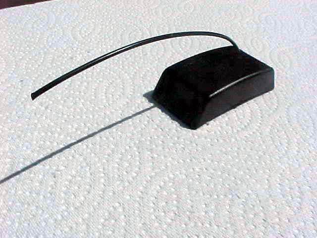
P2E03TPMW2
Oct 04, 2004Tire Pressure Monitoring Transmitter
Equipment Class
DSC - Part 15 Security/Remote Control Transmitter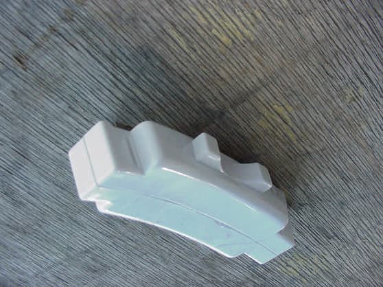
P2E02TPMS2
Feb 05, 2002Tire Pressure Monitor Transmitter
Equipment Class
DSC - Part 15 Security/Remote Control Transmitter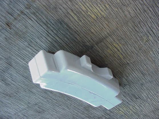
P2E01TPMS2
Jan 24, 2002Tire Pressure Monitor Transmitter
Equipment Class
DSC - Part 15 Security/Remote Control Transmitter