P2E03TPMW2Tire Pressure Monitoring Transmitter
HCI Corporation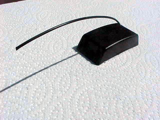
Click to zoom
Application Details
- Equipment Class
- DSC - Part 15 Security/Remote Control Transmitter
- Date of Grant
- Oct 04, 2004
- Application Purpose
- Original Equipment
- Date of Application
- Oct 04, 2004
- Equipment Note
- Tire Pressure Monitoring Transmitter
- Frequency Range
- 433.99000000 - 433.99000000
- Company
- HCI Corporation
- Country
- United States
Documents & Files
Document Text
Text extracted from the exhibit documents filed with the FCC. Open a document above to read the original.
Users Manual
TPM-W204 Tire Pressure Monitoring System User’s Manual HCI Corporation [email protected] Introduction Tire-Safeguard automatically monitors your vehicle tires, and will immediately alert you of abnormal tire pressure and/or temperature, providing a timely warning to you in order for you to take corrective action. Sensor Installation Tools Required: • Tire changing equipment • Tire balancing equipment • Hexagon socket and driver • Metal Cutter • Torque wrench a) De-mount wheel from car and remove tire from wheel. b) Cut mounting band to appropriate length for the wheel. Remove burrs from the cut band end. c) Get correct sensor for the wheel, pass band through the two mounting hole on the lower part of the sensor. d) Wrap the band (with sensor) around the wheel base, insert band end into the band clamp, and then use a socket wrench to advance the worm-gear until the band is slightly pressing the wheel base. e) Adjust band to the lowest areas of the drop center well on the wheel. Move sensor to a position behind (but not touching) the valve. Make sure the sensor is resting on a flat surface. f) Using torque wrench tighten band to 30 inch pounds (4 N-m). The sensor should be pulled down tightly against the wheel base and should not be moveable. g) Cut off excessive band (left about 1 inch). Mount tire on wheel, balance wheel, and mount wheel back on car. h) After sensor installation, turn on vehicle power (but do not start the car). Inflate the tires to proper pressure. Observe that the display shows the pressure and temperature one at a time for all tires. Pressing the control button on the Display shows individual tire pressure and temperature. Operation After installation, the system operates automatically and continuously. When vehicle power is turned on, the display will show the current tire pressure and temperature one-by-one from tire No.1 to No. 4. The display then turns off and only the status light remains lit. A green status light indicates normal pressure and temperature for all tires, otherwise the status light turns red (low tire pressure) or yellow (other warnings) and the corresponding tire indicator(s) and the warning icon(s) are illuminated. Warnings Upon detection of abnormal tire pressure and/or temperature, the system will sound an 8-second alarm and display the warnings. FCC Compliance This equipment has been tested and found to comply with the limits for a class B digital device, pursuant to part 15 of the FCC Rules. These limits are designed to provide reasonable protection against harmful interference in a residential installation. This equipment generates, uses and can radiate radio frequency energy and if not installed and used in accordance with the instructions, may cause harmful interference to radio communications. However, there is no guarantee that interference will not occur in a particular installation. If this equipment does cause harmful interference to radio or television reception, which can be determined by turning the equipment off and on, the user is encouraged to try to correct the interference by one or more of the following measures: • Reorient or relocate the receiving antenna. • Increase the separation between the equipment and receiver. • Connect the equipment into an outlet on a circuit different from that to which the receiver is connected. • Consult the dealer or an experienced radio/TV technician for help. • In order to maintain compliance with FCC regulations, shielded cables must be used with this equipment. Operation with non-approved equipment or unshielded cables is likely to result in interference to radio and TV reception. The user is cautioned that changes and modifications made to the equipment without the approval of manufacturer could void the user's authority to operate this equipment. This device complies with Part 15 of the FCC Rules. Operation is subject to the following two conditions: (1) This device may not cause harmful interference, and (2) This device must accept any interference received, including interference that may cause undesired operation.
Cover Letter(s)
scott From: scott [[email protected]] Sent: Wednesday, August 04, 2004 1:58 PM To: Mike Christensen Subject: FCC ID: P2E3TPMW2 10/5/2004 Mr. Christensen, In order for processing of this application (FCC ID: P2E3TPMW2) to continue, the following issue(s) will have to be addressed: 1) The schematic diagram states that the RF is at 447.725 MHz, which disagrees with the rest of the application. Please clarify. 2) The schematic diagram does not show the oscillators shown in the Block Diagram. Please indicate the reason. 3) Please indicate how the device complies with section 15.231 (a)(2) of the FCC rules. FYI: Although it is not a compliance issue in this case, it appears as if the duty cycle was derived by averaging over more than one pulse train. When calculatin g duty cycle, if the pulse train is less than 100 ms, it is determined over one pulse train, not 100 ms. The item(s) indicated above must be submitted before processing can continue on the above referenced application. Failure to provide the requested information within 60 days of the original e-mail date may result in application dismissal and forfeiture of the filing fee. Also, please note that partial responses increase processing time and should not be submitted. Please upload responses and/or exhibits to the electronic filing website. Your correspondence number is P2E3TPMW2-1. If you have any questions, feel free to contact me. Best Regards, Scott McCutchan Operations Manager Compatible Electronics TCB 114 Olinda Drive Brea, California 92823 Main (714) 579-0500 Direct (714) 579-1489 Fax (714) 579-1850 [email protected] www.celectronics.com Correspondence by Project Project Number: -511601430 Correspondence Number Memo P2E3TPMW2-1 Here are the responses to the following questions you had: 1) The schematic diagram states that the RF is at 447.725 MHz, which disa grees with the rest of the application. Please clarify. The schematic diagram was mistakenly stated that the RF is at 447.725 MHz. Please see the corrected schematic diagram that I will upload. 2) The schematic diagram does not show the oscillators shown in the Block Diagram. Please indicate the reason. The transmitter has a self OSC by Q1 and Y1; the CPU clock is built-in. 3) Please indicate how the device complies with section 15.231 (a)(2) of the FCC rules. I will upload a statement about stopping the transmission in 5 seconds. FYI: Althou gh it is not a compliance issue in this case, it appears as if the duty cycle was derived by averaging over more than one pulse train. When calculating duty cycle, if the pulse train is less than 100 ms, it is determined over one pulse train, not 100 ms. Regarding the duty cycle calculation, our sample transmitter is hardwired to transmit signals all the time for facilitating the tests and that’s the reason you would see continuous pulse trains. In real application the transmission is event driven and would only transmit a few packets each time.
ID Label/Location Info
TPM-W2 FCC ID & Label FCC ID Number of TPM-W2: P2E03TPMW2 FCC Label Proposed Location and Format
Test Report
Report Number: B40628A1 FCC Part 15 Subpart B and FCC Section 15.231 Test Report Tire Pressure Monitor Transmitter Model Number: TPM-W2 114 OLINDA DRIVE, BREA, CALIFORNIA 92823 PHONE: (714) 579-0500 FAX: (714) 579-1850 Page 1 of 16 FCC PART 15, SUBPART B and C TEST REPORT for TIRE PRESSURE MONITOR TRANSMITTER MODEL NUMBER: TPM-W2 Prepared for HCI CORPORATION 11245 – 183 RD STREET #168 CERRITOS, CALIFORNIA 90703 Prepared by:_____________________ JAMES ROSS Approved by:____________________ MICHAEL CHRISTENSEN COMPATIBLE ELECTRONICS INC. 114 OLINDA DRIVE BREA, CALIFORNIA 92823 (714) 579-0500 DATE: JULY 16, 2004 REPORT APPENDICES TOTAL BODY A B C D E PAGES 16 2 2 2 10 15 47 This report shall not be reproduced except in full, without the written approval of Compatible Electronics. Report Number: B40628A1 FCC Part 15 Subpart B and FCC Section 15.231 Test Report Tire Pressure Monitor Transmitter Model Number: TPM-W2 114 OLINDA DRIVE, BREA, CALIFORNIA 92823 PHONE: (714) 579-0500 FAX: (714) 579-1850 Page 2 of 16 TABLE OF CONTENTS Section / Title PAGE GENERAL REPORT SUMMARY 4 SUMMARY OF TEST RESULTS 4 1. PURPOSE 5 2. ADMINISTRATIVE DATA 6 2.1 Location of Testing 6 2.2 Traceability Statement 6 2.3 Cognizant Personnel 6 2.4 Date Test Sample was Received 6 2.5 Disposition of the Test Sample 6 2.6 Abbreviations and Acronyms 6 3. APPLICABLE DOCUMENTS 7 4. DESCRIPTION OF TEST CONFIGURATION 8 4.1 Description of Test Configuration - EMI 8 4.1.1 Cable Construction and Termination 9 5. LISTS OF EUT, ACCESSORIES AND TEST EQUIPMENT 10 5.1 EUT and Accessory List 10 5.2 EMI Test Equipment 11 6. TEST SITE DESCRIPTION 12 6.1 Test Facility Description 12 6.2 EUT Mounting, Bonding and Grounding 12 7. TEST PROCEDURES 13 7.1 Radiated Emissions (Spurious and Harmonics) Test 13 7.2 Bandwidth of the Fundamental 15 8. CONCLUSIONS 16 Report Number: B40628A1 FCC Part 15 Subpart B and FCC Section 15.231 Test Report Tire Pressure Monitor Transmitter Model Number: TPM-W2 114 OLINDA DRIVE, BREA, CALIFORNIA 92823 PHONE: (714) 579-0500 FAX: (714) 579-1850 Page 3 of 16 LIST OF APPENDICES APPENDIX TITLE A Laboratory Recognitions B Modifications to the EUT C Additional Models Covered Under This Report D Diagrams, Charts, and Photos • Test Setup Diagrams • Radiated Emissions Photos • Antenna and Effective Gain Factors E Data Sheets LIST OF FIGURES FIGURE TITLE 1 Plot Map And Layout of Radiated Test Site Report Number: B40628A1 FCC Part 15 Subpart B and FCC Section 15.231 Test Report Tire Pressure Monitor Transmitter Model Number: TPM-W2 114 OLINDA DRIVE, BREA, CALIFORNIA 92823 PHONE: (714) 579-0500 FAX: (714) 579-1850 Page 4 of 16 GENERAL REPORT SUMMARY This electromagnetic emission test report is generated by Compatible Electronics Inc., which is an independent testing and consulting firm. The test report is based on testing performed by Compatible Electronics personnel according to the measurement procedures described in the test specifications given below and in the "Test Procedures" section of this report. The measurement data and conclusions appearing herein relate only to the sample tested and this report may not be reproduced without the written permission of Compatible Electronics, unless done so in full. This report must not be used to claim product endorsement by NVLAP, NIST or any other agency of the U.S. Government. Device Tested: Tire Pressure Monitor Transmitter Model Number: TPM-W2 S/N: N/A Product Description: See Expository Statement. Modifications: The EUT was not modified in order to meet the specifications. Manufacturer: HCI Corporation 11245 – 183 rd Street #168 Cerritos, California 90703 Test Date: June 24 and 28, 2004 Test Specifications : EMI requirements CFR Title 47, Part 15 Subpart B; and Subpart C, Sections 15.205, 15.209, and 15.231 Test Procedure: ANSI C63.4 Test Deviations: The test procedure was not deviated from during the testing. SUMMARY OF TEST RESULTS TEST DESCRIPTION RESULTS 1 Conducted RF Emissions, 150 kHz - 30 MHz This test was not performed because the EUT operates on DC power only and cannot be plugged into the AC public mains. 2 Radiated RF Emissions, 10 kHz - 4340 MHz Complies with the Class B limits of CFR Title 47, Part 15, Subpart B; and Subpart C, sections 15.205, 15.209, and 15.231. Report Number: B40628A1 FCC Part 15 Subpart B and FCC Section 15.231 Test Report Tire Pressure Monitor Transmitter Model Number: TPM-W2 114 OLINDA DRIVE, BREA, CALIFORNIA 92823 PHONE: (714) 579-0500 FAX: (714) 579-1850 Page 5 of 16 1. PURPOSE This document is a qualification test report based on the Electromagnetic Interference (EMI) tests performed on the Tire Pressure Monitor Transmitter Model Number: TPM-W2. The EMI measurements were performed according to the measurement procedure described in ANSI C63.4. The tests were performed in order to determine whether the electromagnetic emissions from the equipment under test, referred to as EUT hereafter, are within the Class B specification limits defined by CFR Title 47, Part 15, Subpart B; and Subpart C, sections 15.205, 15.209, and 15.231. Report Number: B40628A1 FCC Part 15 Subpart B and FCC Section 15.231 Test Report Tire Pressure Monitor Transmitter Model Number: TPM-W2 114 OLINDA DRIVE, BREA, CALIFORNIA 92823 PHONE: (714) 579-0500 FAX: (714) 579-1850 Page 6 of 16 2. ADMINISTRATIVE DATA 2.1 Location of Testing The EMI tests described herein were performed at the test facility of Compatible Electronics, 114 Olinda Drive, Brea, California 92823. 2.2 Traceability Statement The calibration certificates of all test equipment used during the test are on file at the location of the test. The calibration is traceable to the National Institute of Standards and Technology (NIST) . 2.3 Cognizant Personnel HCI Corporation Steve Wong President Compatible Electronics, Inc. James Ross Test Engineer Michael Christensen Sr. Test Engineer 2.4 Date Test Sample was Received The test sample was received prior to its qualification testing of June 24, 2004. 2.5 Disposition …
Text truncated - open the document above for the full version.
Contact Information
Applicant
Steve Wong(President)
Technical Contact
Compatible ElectronicsMichael P Christensen
[email protected]714-579-0500
114 Olinda Drive · Brea, California · United States
Test Firm
Compatible ElectronicsScott McCutchan
714-579-0500Fax: 714-579-1850
Technical Specifications
| # | Rule Parts | Frequency Range | Power Output |
|---|---|---|---|
| 1 | 15.231 | 433.99 MHz - 433.99 MHz | - |
Other Applications from HCI Corporation
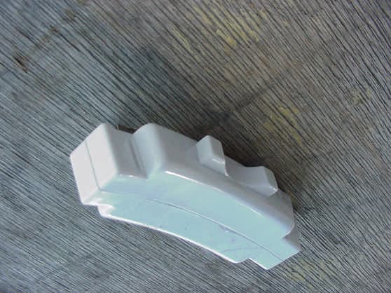
P2E02TPMS2
Feb 05, 2002Tire Pressure Monitor Transmitter
Equipment Class
DSC - Part 15 Security/Remote Control Transmitter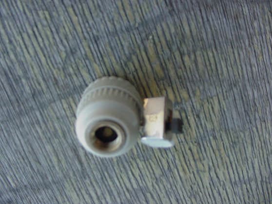
P2E01TPMS1
Jan 24, 2002Tire Pressure Transmitter
Equipment Class
DSC - Part 15 Security/Remote Control Transmitter
P2E01TPMS2
Jan 24, 2002Tire Pressure Monitor Transmitter
Equipment Class
DSC - Part 15 Security/Remote Control Transmitter