P2HCVGPS-1820Cellvic GPS Receiver
NAVIUS Co., Ltd.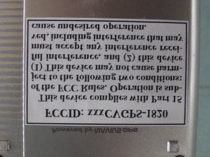
Click to zoom
Application Details
- Equipment Class
- JBP - Part 15 Class B Computing Device Peripheral
- Date of Grant
- Dec 05, 2001
- Application Purpose
- Original Equipment
- Date of Application
- Dec 05, 2001
- Equipment Note
- Cellvic GPS Receiver
- Company
- NAVIUS Co., Ltd.
- Country
- South Korea
Documents & Files
Document Text
Text extracted from the exhibit documents filed with the FCC. Open a document above to read the original.
Users Manual
EMI TEST REPORT Report Number : KSQ-FCC011101 Appendix BUser's Manual Cellvic GPS Quick Installation Guide User’s Manual FCC NOTICE This device complies with Part 15 of the FCC Rules. Operation is subject to the following two conditions: (1) This device may not cause harmful interference, and (2) This device must accept any interference received, including interference that may cause undesired operation. This equipment has been tested and found to comply with the limits for a Class B digital device, pursuant to part 15 of the FCC Rules. These limits are designed to provide reasonable protection against harmful interference in a residential installation. This equipment generates, uses and can radiate radio frequency energy and, if not installed and used in accordance with the instructions, may cause harmful interference to radio communication. However, there is no guarantee that interference will not occur in a particular installation. If this equipment does cause harmful interference to radio or television reception, which can be determined by turning the equipment off and on, the user is encouraged to try to correct the interference by one or more of the following measures : l Reorient or relocate the receiving antenna. l Increase the separation between the equipment and receiver. l Connect the equipment into an outlet on a circuit difference from that to which the receiver is connected. l Consult the dealer of an experienced radio/TV technician for help. NOTE : The manufacturer is not responsible for any radio or TV interference caused by unauthorized modifications to this equipment. Such modifications could void the user's authority to operate the equipment. [1] NAVIUS GPS external appearance explanation (1) Power key (2) IR port(IrDA) (3) Upper direction direction Key (4) Left side direction Key (5) Down direction Key (6) Reset (7) Serial Port (8) AC power jack. (9) GPS Key(LED) (10) ENTER Key(LED) (11) Stylus Pen (12) Outside GPS ant. Jack (13) LCD & Touch Screen (14) Recognition Panel & Fixed icons (a) Handy-strip Holder (b) Lithium- ion electric cell lid (Attention! Sample product can be different from above condition.) [2] Cellvic GPS specification (1) PDA. - Cellvic OS 1.21/GPS Edition - 160 x 160 dots LCD, 2/4/16 GREY level support, and 0.26 dots pitch - 8MB DRAM, 2MB FLASH - Multimedia Card 32/64MB(option) - 7 keys - 1 SERIAL PORT(MODEM,CDMA and PC) - 1 IrDA PORT (2) GPS - Conexant Zodiac 12 channel GPS chipsets - Zodiac Chipset has CityTracker™ for improving performance in high blockage environment - Built-in GPS antenna, External GPS antenna available(option) - Supports NMEA-0183 V2.1 protocol - TTFF (Time To First Fix) is below 60 seconds - Horizontal error average 10 meter (3) POWER - Lithium-Ion 3.7V 1,550mA Rechargeable Battery built-in (option) - AAA x 3-battery pack - AC/DC adaptor 5V 600mA (option) - Cigar-jack adapter (option) - Lithium ion 9 ~ 10 hours, AAA pack 4 ~ 5 hours(When turn on GPS) [Caution]. Sample product does not support warning of low battery. So, you should charge Li-ion battery regularly. [3] Product overview (1) What is GPS? The Global Positioning System uses 24 satellites above the earth to determine the accurate position. You can get latitude, longitude and altitude with accuracy to a few meters. Also, GPS receivers can determine speed and direction. GPS devices receive spread spectrum RF signal from a minimum of four satellites and use triangulation technique to calculate time, position and velocity. GPS receivers typically output the information for user once per a second. (2) Benefits of Cellvic GPS GPS Inside! The unit combines powerful GPS location technology with successful Cellvic PDA technology. Using the GPS technology of Navius, the device can provide various Location Based Service. The unit is a cost effective navigation system. There is no need to carry both PDA and GPS receiver. Unlike general handheld GPS devices, Cellvic GPS provides large memory for saving waypoints, routes and tracks. Using Autosync technology, the device can backup and restore data to/from a PC. Optional 16/32MB multimedia card can provide 4/16 grey vector map positioning service. Powerful PDA The unit provides a perfect Personal Information Management tool. The device supports uni-stroke character recognition for multiple European languages. The device has CDMA Internet connection port for various Internet applications(Email, Micro web browser and LBS service). The device supports data-sync with Microsoft Outlook. Developer Support Free SDK based on GNU C/C++ compiler helps you to develop GPS applications. It provides APIs for GUI, MMC access and GPS decoding. (3) Use the Cellvic GPS at your own risk Cellvic GPS uses GPS to determine user’s position. Signals of GPS satellites are very weak, so you cannot determine your position under bad condition. Also, continuous operation of GPS is limited within battery capacity. We recommend that you would never depend only upon Cellvic GPS to navigate. Unlike professional handheld GPS, the unit is not waterproof and does not resist external shock. Operating temperature is limited within +10~+40 degree centigrade. [4] GeoQuest (1) What is GeoQuest? [GeoQuest Brief] 1) It is a default GPS application embedded in Cellvic GPS. 2) It has many functions of general handheld GPS. (i.e. Waypoint, route, Track logging and mapping) [Basic Screens] 1) Startup screen, Setting screen, Detail Setting screen 2) Position information, Satellite Information 3) Data manager: Waypoint screen, Route screen, Track screen. [5]To turn on, turn off GPS. (1) To turn on GPS [Method 1] When power turns off, click GPS key (G letter is craved to key). [Method 2] After turn on power using power key, Execute GeoQuest icon with a stylus pen in program manager(figure 1), or run other GPS application. Tip! Confirmation of GPS working is available that LED of GPS key blinks every 1-second. Caution! Sample product can be different from above condition. (2) To …
Text truncated - open the document above for the full version.
Block Diagram
EMI TEST REPORT Report Number : KSQ-FCC011101 Appendix ASchematics/Block Diagram CVGPS-1820 Block Diagram GPS Module Dragonball MC68EZ328 7 Key Switch IrDA Flash 1M*16bit RS232 Port Battery Charge Controller Regulator DRAM 1M*16bit Li-Ion Battery 1550mAh Regulator External Power (6.0VDC) +3.0V(GPS Module) +3.3V Passive GPS Antenna Active GPS Antenna RF Connector Switch 32.768KHz XTAL Control ON/OFF RESET LCD 160*160 4glay TouchPad EL Backlight DRAM 4M*16bit Option AAA Alkaline Battery(3EA) Option Buzzer +3.0V MMC 32MB
External Photos
EMI TEST REPORT Report Number : KSQ-FCC011101 Page 15 / 22 5.External Photographs 5.1EUT: Front View 5.2EUT: Rear View EMI TEST REPORT Report Number : KSQ-FCC011101 Page 16 / 22 5.3EUT: Label View 5.4EUT: Internal View
ID Label/Location Info
EMI TEST REPORT Report Number : KSQ-FCC011101 Page 12 / 22 3.Product Labelling Requirements 3.1FCC Statement Product shall be labelled the following statement in a conspicuous location on the device: FCCID: P2HCVGPS-1820 This device complies with Part 15 of the FCC Rules. Operation is subject to the following two conditions: (1) This device may not cause harmful interference, and (2) this device must accept any interference received, including interference that may cause undesired operation. MADE IN KOREA When the device is so small or for such use that it is not practicable to place the statement on it, the information shall be placed in prominent location in the instruction manual or pamphlet supplied to the user. However, the FCC identifier or unique identifier, as appropriate, must be displayed on the device. 3.2Label Location
Internal Photos
EMI TEST REPORT Report Number : KSQ-FCC011101 Page 17 / 22 6.Internal Photographs 6.1EUT: Main Board, Component View EMI TEST REPORT Report Number : KSQ-FCC011101 Page 18 / 22 6.2EUT: Main Board, Circuit View EMI TEST REPORT Report Number : KSQ-FCC011101 Page 19 / 22 6.3EUT: GPS Board, Component View EMI TEST REPORT Report Number : KSQ-FCC011101 Page 20 / 22 6.4EUT: GPS Board, Circuit View
Test Report
EMI TEST REPORT FCC PART 15 CLASS B for NAVIUS Co., Ltd. 6F Seoyang Bldg. #1460-1, Seochodong, Seochogu, Seoul 137-070, KOREA on the Cellvic GPS Receiver CVGPS-1820 Issued Date : November 6, 2001 Report Number : KSQ-FCC011101 Prepared By: Test Date:November 2, 2001 Test Engineer:H. S. Lee Printed NameSignature Compliance Engineer:J. J. Ha Printed NameSignature Korea Standard Quality Laboratories Testing Laboratories for EMC and Safety Compliance 102, Jangduk-Dong, Hwasung-City, Kyeonggi-Do 445-855, KOREA This report may not be reproduced without the full written consent of Korea Standard Quality Laboratories. EMI TEST REPORT Report Number : KSQ-FCC011101 Page 1 / 22 Table of Contents 1.General Information 1.1Introduction3 1.2Product Description for Equipment Under Test (EUT)3 1.3Support Equipment4 1.4External I/O Cabling4 1.5Special Accessories4 1.6EUT Modifications4 1.7Configuration of Test System5 2.Test Performed 2.1Conducted Emission Measurements6 2.1.1Test Description6 2.1.2Test Equipments6 2.1.3Test Environments6 2.1.4Test Limits6 2.1.5Test Procedure6 2.1.6Test Results7 2.1.7Test Data7 2.1.8Plots of Test Data8 2.2Radiated Emission Measurements9 2.2.1Test Description9 2.2.2Test Equipments9 2.2.3Test Environments9 2.2.4Test Limits9 2.2.5Test Procedure10 2.2.6Field Strength Calculation10 2.2.7Test Results10 2.2.8Test Data11 EMI TEST REPORT Report Number : KSQ-FCC011101 Page 2 / 22 Table of Contents(cont'd) 3.Product Labelling Requirements 3.1FCC Statement12 3.2Label Location12 4.Test Setup Photographs 4.1Conducted Emission: Front View13 4.2Conducted Emission: Rear View13 4.3Radiated Emission: Front View14 4.4Radiated Emission: Rear View14 5.External Photographs 5.1EUT: Front View15 5.2EUT: Rear View15 5.3EUT: Label View16 5.4EUT: Internal View16 6.Internal Photographs 6.1EUT: Main Board, Component View17 6.2EUT: Main Board, Circuit View18 6.3EUT: GPS Board, Component View19 6.4EUT: GPS Board, Circuit View20 6.5EUT: Memory Board, Component View21 6.6EUT: Memory Board, Circuit View22 Appendix A - EUT Schematics/Block Diagram Appendix B - User's Manual EMI TEST REPORT Report Number : KSQ-FCC011101 Page 3 / 22 1.General Information 1.1Introduction The EMI Measurements and Test Report of a Class B Information Technology Equipment is prepared on behalf of named applicant in accordance with the ANSI C63.4-1992. The detailed description of the measurement facility was found to be in compliance with the requirement of Section 2.948 of the FCC Rules. All radiated emission and conducted emission measurements are performed manually at Korea Standard Quality Laboratories. The radiated emission measurements required by the FCC Rules were performed on 3 meter or 10 meter, Open Area Test Site (OATS), test range maintained by Korea Standard Quality Laboratories (KSQ), 102 Jangdeok-Dong, Hwaseong-City, Kyeonggi-Do, KOREA. Complete ANSI 63.4-1992 description and site attenuation measurement data records are maintained at the test facility and have been placed on file with the Federal Communications Commission. The power line conducted emission measurements were performed in a shielded enclosure also located at the same facility. 1.2Product Description for Equipment Under Test (EUT) NAVIUS Co., Ltd.'s Cellvic GPS (Global Positioning System) Receiver or the "EUT" as referred to in this report is powerful & efficient mobile computing platform for real PDA. Main Features of EUT are: Motorola 68EZ328 16MHz 160 x 160 dots 4/16 gray LCD, 0.26dot pitch FLASH 2MB, RAM 8MB Multimedia Card 16/32MB Option CellVic OS (English, Chinese and Korean) IrDA or RS-232C Interface Li-ion 3.7V 1,550mAh Rechargeable Battery or AAA x 3 12V/24V DC Auto Adapter, 110/220V AC Adapter 12 Channel GPS Receiver & Internal Passive Antenna External Active Antenna Accuracy 15M (95%) without S/A EMI TEST REPORT Report Number : KSQ-FCC011101 Page 4 / 22 1.3Support Equipment DescriptionModel NumberSerial NumberManufacturerRemarks Host ComputerJT4102JT004000053Jooyontech ComputerATX VGA MonitorDP15LSH1EK403730Samsung Electronics15" KeyboardSEM-DT3595001529Samsung ElectronicsPS/2 MouseOK-520noneA4-TechSerial Printer2225C3037S84200Hwelett PackardInkjet PC CameraPCC2200PK2-0020Pro-chipsUSB JoystickDHA-2000noneDahwoon ElectronicsGame SpeakerGL-2000noneComsources- MicrophoneJPM601noneHi-sonic- AC AdapterHW0.1noneSalcompfor EUT GPS ReceiverCVGPS-1820noneNavius Co., Ltd.EUT 1.4External I/O Cabling DescriptionLength (m)Port/FromPort/ToRemarks Video Cable1.5Dsub/HostMonitorShielded Keyboard Cable2.0PS2/HostKeyboardShielded Mouse Cable2.0PS2/HostMouseShielded Printer Cable1.5Dsub/HostPrinterShielded Serial Cable1.5Dsub/HostEUTShielded USB Cable2.0USB/HostPC CameraShielded Joystick Cable1.5Dsub/HostJoystickShielded Speaker Cable1.0Jack/HostSpeakerShielded Microphone Cable2.0Jack/HostMicrophoneShielded Antenna Cable5.0EUTGPS AntennaNon-shielded 1.5Special Accessories As shown in section 1.7, all interface cables used for compliance testing are shielded as normally supplied or by use respective component manufacturers. 1.6EUT Modifications No modifications were made to the EUT in order to achieve and maintain compliance to the standards described in this report. EMI TEST REPORT Report Number : KSQ-FCC011101 Page 5 / 22 1.7Configuration of Test System Host Computer Video Cable with Ferrite Core VGA MonitorPrinter Mouse Cable (part of mouse) Keyboard Cable (part of keyboard) Mouse Keyboard EUT USB Cable PC Camera GPS Antenna Printer Cable with Ferrite Core Speaker/Mic Sound Cable Serial Cable EMI TEST REPORT Report Number : KSQ-FCC011101 Page 6 / 22 2.Test Performed 2.1Conducted Emission Measurements 2.1.1Test Description The power line conducted emission measurements were performed in a shielded enclosure, using the setup in accordance with ANSI C63.4-1992 conducted emission measurement procedure. 2.1.2Test Equipments DescriptionManufacturerModel NumberSerial NumberCal. Due Spectrum AnalyzerAdvantest3261A2172024010, 2002 LISN1Electro MetricsANS-25/2253510,…
Text truncated - open the document above for the full version.
Test Setup Photos
EMI TEST REPORT Report Number : KSQ-FCC011101 Page 13 / 22 4.Test Setup Photographs 4.1Conducted Emission: Front View 4.2Conducted Emission: Rear View EMI TEST REPORT Report Number : KSQ-FCC011101 Page 14 / 22 4.3Radiated Emission: Front View 4.4Radiated Emission: Rear View
Contact Information
Applicant
Kangwon Lee(Ast. Chief Researcher)
Test Firm
Korea Standard Quality LaboratoriesSung-goo Kim
Technical Specifications
| # | Rule Parts | Frequency Range | Power Output |
|---|---|---|---|
| 1 | 15B | - | - |
Other Applications from NAVIUS Co., Ltd.

P2HNJ-102
Apr 21, 2005GPS Receiver
Equipment Class
JBP - Part 15 Class B Computing Device Peripheral
P2HNSA-U3
May 23, 2004gps receiver
Equipment Class
JBP - Part 15 Class B Computing Device Peripheral