P3M2Information collector with Bluetooth
C Technologies AB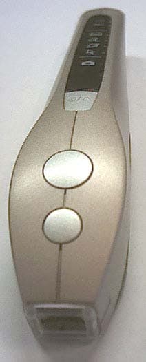
Click to zoom
Application Details
- Equipment Class
- DXX - Part 15 Low Power Communication Device Transmitter
- Date of Grant
- Jan 13, 2003
- Application Purpose
- Original Equipment
- Date of Application
- Jan 06, 2003
- Equipment Note
- Information collector with Bluetooth
- Frequency Range
- 2402.00000000 - 2480.00000000
- Company
- C Technologies AB
- Country
- Sweden
Documents & Files
Document Text
Text extracted from the exhibit documents filed with the FCC. Open a document above to read the original.
Users Manual
The Pen User’s Guide for Prototype EP2B The BLUETOOTH trademark is owned by its proprietor and used by C Technologies AB under license. Safety precautions Warning! Do not expose the Pen to naked flames or extreme tempera- tures, otherwise the battery may explode and cause injury! Warning! Do not allow children to play with the Pen. They could injure themselves or others, or accidentally damage the Pen! Contents Introduction 4 Parts of the Pen 4 Front 4 Back 4 Functions of the Pen 5 Selecting C-Read, C-Write, C-URL or C-Mouse 5 Selecting C-Photo 5 Pen battery 6 Connecting to a host device 6 USB connection 7 Bluetooth connection 7 Connecting to a Bluetooth host device for the first time 7 Connecting to a previously paired host device 8 Changing the host device 8 Using the Pen 9 Holding the Pen 9 Reading text (C-Read) 10 Writing text (C-Write) 10 Reading a URL (C-URL) 12 Using the Pen as a mouse (C-Mouse) 12 Taking photographs (C-Photo) 12 Additional information 13 Upgrading the software 13 Care and maintenance 14 Precautions 14 Cleaning 14 Disposing of the Pen 14 Technical specifications 14 Approvals 16 Troubleshooting 17 C-Write Prototypes 20 Letters, digits and shift 20 Special characters 21 Accents and umlaut 21 Symbols 22 4 C-ReadC-URLC-Photo C-MouseC-Write Bluetooth indicator Battery indicator Function/On/Off button Bluetooth antenna (under cover) A-buttonB-button Autotrigger Surface mode Aperture Macro mode Autotrigger Normal mode USB port Focus switch Reset Introduction The Pen is an advanced, multi-functional, digital, hand-held device that can read and write text, take digital photographs, and be used as a mouse for your computer. The Pen is designed for use with a host device such as a personal or laptop computer, a mobile phone or a hand-held device. Information is transferred between the Pen and the host by a Universal Serial Bus (USB) connector or Bluetooth™ wireless technology. To get the most out of your Pen, it is a good idea to learn the different parts and functions before you start to use it. Parts of the Pen Front Each function of the Pen is represented by a symbol on the display, and each symbol has a corresponding Light Emitting Diode (LED) indicator. When a function is selected, its indicator is lit green. Back 5 Functions of the Pen The Pen has the following functions: C-Read read text using OCR (optical character recognition); C-Write write text by drawing letters or symbols on a patterned surface; C-URL read a URL (universal resource locator) and start a browser; C-Mouse use the Pen as a mouse for a computer; C-Photo take normal or close-up digital photographs. Selecting C-Read, C-Write, C-URL or C-Mouse Move the Focus switch at the back of the Pen to the Surface mode position (). The Pen is now set for C-Read, C-Write, C-URL or C-Mouse. C-Read is the default function. If you click the Function button on the front of the Pen, the next function is selected and its indicator is lit. Click the Function button repeatedly until the desired function is selected. Note that C-Photo cannot be selected by using the Function button. If the Focus switch is in the Surface mode position when the Pen is switched on, C-Read is selected by default and the C-Read indicator is lit. Selecting C-Photo Move the Focus switch to the Normal () or Macro () mode positions. The Pen is now set for normal or macro photography respectively, and the C-Photo indicator is lit. The Function button is disabled. If the Focus switch is set for photography when the Pen is switched on, C-Photo is selected by default. To change to another function, move the Focus switch to the Surface mode position and select the desired function. 6 Pen battery The battery of the Pen is not fully charged when the Pen is delivered. We recommend that you charge the battery before you use the Pen for the first time. Plug the USB connector of the charger adapter into the USB port on the back of the Pen and connect the charger adapter to a mains electrical supply. The battery can only be charged in an ambient tempera- ture of between +5°C (+41°F) and +45°C (+113°F). Warning! Do not expose the Pen to naked flames or extreme tempera- tures, otherwise the battery may explode and cause injury! Extreme temperatures also affect the life and efficiency of the battery. When the battery is charged after a long period of inactivity, it pre- charges for between 5 and 30 minutes before normal charging starts. It takes approximately 3 hours to fully charge the battery from empty, but 90% of the full charge is reached after 1 hour. You can use the Pen while it is charging, but not when it is pre-charging. If a USB connection (see below) is used for communication between the Pen and the host device, the battery charges through the USB cable. Charging times may vary, depending on your host device. The Battery indicator on the Pen’s display shows the status of the battery. Battery indicatorIndication Flashing redLow battery Steady redPre-charging Flashing greenCharging with charger cable or USB cable Steady greenFully charged battery Connecting to a host device You can connect the Pen to the host device either by using Bluetooth wireless technology, either integrated into the device or as an external adapter, or by using a USB cable. To use all the functions of the Pen, the software that accompanies the Pen must be installed on the host device. If you connect to the host via a USB cable, some functions such as C-Write, C-Read and C-Mouse can be used 7 without the host software being installed. If the Pen fails to communicate with the host, please refer to the Trouble- shooting section at the end of this User’s Guide. USB connection If the host device is equipped with a USB interface, you can use a USB cable to communicate with the host. 1.Connect a USB cable between the USB interface of the host and the USB port on the back of the Pen. 2.Press the On/Off button for one second to switch the Pen on. A USB connection is established between the P…
Text truncated - open the document above for the full version.
Block Diagram
U S B ARGUS 3.3V I/O 2.5V Core CMOS VGA Sensor 3.3V Monitor DS2760 2.5V 150mA Lin 2.5V 150mA SDRAM 64Mbit 3.3V NAND 64Mbit 3.3V Buzz Illumination Leds LATCH Switches 2 x Buttons Autotrigger Optics position VBAT 3.3V 3.3V A D A D I2C DAT ADR Xtal 12MHz USB or Mains Adapter +5V/500mA Charger ON/OFF Logic Picodous 3.3V I/O 2.8V I/O Siri Flisa Xtal 13MHz IRQ 2.8V Leds 2.8V 150mA Lin 2.8V 150mA 3.3V 500mA Lin 3.3V 500mA 2.8V2.5V Voltage detect (Soft start) 3.3V VBAT rst, sync, stby, clk HUGIN OPTICAL MODULE Pixel Interface Fuse BT_RESET LiIon 400mAh CPU Prote ction RX- Balun Radio ASIC ANT T2 TX- Balun Switch Antenna Filter Loop Filter VCO Tank FLASH Memory 13MHz Crystal Voltage Regulation WAKE_UP DETACH GND B3 R1 R2 T1 C6 VCC C4 VCC_IO C2 ON RESET# POR NC NC NC NC NC R4 R5 R6 T4 T5 T6 C3 Radio Module B4 C1 ADDR DATA CTRL R3 C5 NC PBA 313 01/2 Baseband B1 D- D+ B2 USB TXD RTS RXD CTS A5 A6 B5 B6 UART PCM_OUT PCM_CLK PCM_IN PCM_SYNC A1 A2 A3 A4 PCM T3 GND GND GND GND I2C_DATA I2C_CLK Block diagram for Ericsson Bluetooth modules ROK 101 007 and ROK 101 008
External Photos
1(2) External photos FCC ID: P3M2 2(2)
ID Label/Location Info
Y/W 0120 MADE IN SWEDEN CT-151018R1B CT-151020RXX DDMMYYXXXXX MADE IN TAIWAN Wistron Ne Web CT-151020RXX DDMMYYXXXXX MADE IN TAIWAN Wistron Ne Web CT-151020RXX DDMMYYXXXXX MADE IN TAIWAN Wistron Ne Web Scale 5:1 Scale 1:1 15-RL251007 pa2 Label Bz Mate 2002-03-07 Magnus Waldt FCC ID P3M2 FCC ID P3M2 FCC ID P3M2 fcc id: P3M1 R R C US LISTED I.T.E 10A LISTED XXXXXX LISTED XXXXXX LISTED XXXXXX
Internal Photos
1(5) Internal photos FCC ID: P3M2 2(5) 3(5) 4(5) 5(5)
Operational Description
DOKUMENT - DOCUMENT 1(7) Uppgjord - Prepared Telefon - Telephone Nr - No. Kåre Lindkvist +46 (0) 46 5401 123 CTech-02:0165 Godkänd - Approved Datum - Date Rev Fil - File 2002-05-15 A Operational_Desc Operational description BzMate Operational description BzMate ...............................................................................................................1 1.1 Electrical block schematics .......................................................................................................2 1.2 Product operation description ...................................................................................................2 1.3 Operation details of RF Module “Flisa” ...................................................................................3 1.3.1 Block diagram .......................................................................................................................3 1.3.2 Block diagram of radio ASIC............................................................................................4 1.4 Details of antenna system..........................................................................................................5 1.5 PCB Layout / Grounding...........................................................................................................6 1.5.1 Photos of PCB, RF parts ...................................................................................................7 DOKUMENT - DOCUMENT 2(7) Uppgjord - Prepared Telefon - Telephone Nr - No. Kåre Lindkvist +46 (0) 46 5401 123 CTech-02:0165 Godkänd - Approved Datum - Date Rev Fil - File 2002-05-15 A Operational_Desc 1.1 Electrical block schematics 1.2 Product operation description The device is a combined text-reader and digital camera. It is based on a 72MHz ARM CPU, connected to 64Mbit SDRAM (72MHz, 3.3V) and 64Mbit NAND flash memory (3.3V). Images are grabbed with the optical module (3.3V, Main clock 2MHz, resolution 640x480 pixels). These images are converted to text or JPEG-images based on which application is currently running. The images or text is sent to a PC via Bluetooth (HID and basic imaging profiles) or USB (HID profile). The user interface is based on 3 switches and a buzzer. Photo mode Read mode Switch 1 Grab image size 640x480 Scan text Switch 2 Grab image size 320x240 Carriage return Switch 3 On/Off/Function selector On/Off/Function selector The device is powered by a LiIon battery (3.7V / 410mAh), with 3 linear regulators (3.15V/~150mA, 2.8V/~50mA, 2.5V/~100mA). The LiIon battery is supervised by a protection IC to prevent failure conditions. DOKUMENT - DOCUMENT 3(7) Uppgjord - Prepared Telefon - Telephone Nr - No. Kåre Lindkvist +46 (0) 46 5401 123 CTech-02:0165 Godkänd - Approved Datum - Date Rev Fil - File 2002-05-15 A Operational_Desc 1.3 Operation details of RF Module “Flisa” 1.3.1 Block diagram Items marked in yellow is integrated in the radio ASIC. All blocks except the antenna is integrated in the RF module. DOKUMENT - DOCUMENT 4(7) Uppgjord - Prepared Telefon - Telephone Nr - No. Kåre Lindkvist +46 (0) 46 5401 123 CTech-02:0165 Godkänd - Approved Datum - Date Rev Fil - File 2002-05-15 A Operational_Desc 1.3.2 Block diagram of radio ASIC The RF asic uses a heterodyne receiver architecture with an intermediate frequency of 3.0 MHz with the intermediate frequency filters integrated on chip. The receiver consist of an low noise amplifier (LNA) followed by an image rejection mixer. The intermediate frequency signal processing blocks consist of a bandpass filter (BPF),a hardlimiter (HL),a frequency discriminator (DET)and a lowpass filterwith offset compensation (PDB). The RF asic also contains a synthesizer consisting of a phase detector (PHD), charge pump, loop and regulator filters (external), a prescaler (PSC), modulus logic and a voltage controlled oscillator (VCO). The transmitter utilizes direct modulation on the single VCO, the bit-stream data is shaped with the gaussian shaping filter (GLPF) before the RF carrier is modulated. The transmitter further contains a VCO buffer and a power amplifier (PA). DOKUMENT - DOCUMENT 5(7) Uppgjord - Prepared Telefon - Telephone Nr - No. Kåre Lindkvist +46 (0) 46 5401 123 CTech-02:0165 Godkänd - Approved Datum - Date Rev Fil - File 2002-05-15 A Operational_Desc 1.4 Details of antenna system Parameter Value Input and output impedance of antenna pin on RF module 50 Ohm Antenna peak gain measured in device -3.2 dBd Antenna type Mitsubishi AHD1403-244ST06 Antenna mechanical spec Antenna radiation pattern XY plane on evaluation PCB Antenna radiation pattern YZ plane on evaluation PCB DOKUMENT - DOCUMENT 6(7) Uppgjord - Prepared Telefon - Telephone Nr - No. Kåre Lindkvist +46 (0) 46 5401 123 CTech-02:0165 Godkänd - Approved Datum - Date Rev Fil - File 2002-05-15 A Operational_Desc 1.5 PCB Layout / Grounding Top layer Bottom layer RF Module Bluetooth baseband IC Antenna signal Antenna feed DOKUMENT - DOCUMENT 7(7) Uppgjord - Prepared Telefon - Telephone Nr - No. Kåre Lindkvist +46 (0) 46 5401 123 CTech-02:0165 Godkänd - Approved Datum - Date Rev Fil - File 2002-05-15 A Operational_Desc 1.5.1 Photos of PCB, RF parts Top side Bottom side Bluetooth Baseband IC RF module Crystal Antenna feed Antenna
Test Report
AHD140308A2446JR Surface Mountable Dielectric Chip Antennas May-2000 Mitsubishi Materials Corporation 1/2 AHD140308A2446JR 1. Features a) Small sizes and low profile b) Wide frequency range 2. Specifications TypeAHD140308A2446JR Dimensions13.5 × 3 × 0.8 mm Operating frequency2400 – 2484 MHz Operating temperature-25 - +85 °C 3. Characteristics (Reference) Bandwidth in VSWR ≤ 2140 MHz Gain –peak-0 dBd Gain –average--6.6 dBd Radiation Efficiency36 % Preliminary 4. Dimensions 13.5 +0.2 -0.2 3.0 +0.2 -0.2 0.3 1.0 2.0 1.0 (2) (1) (3) (3)(3) (1) in/out terminal (2) GND (3) Fixing Electrode (should be connected to the floating pad) Thickness: 0.8mm 5. Recommended land pattern Note: *1 We recommend to make ground plane on area ‘B’. You may not make ground plane on area ‘A’. *2 Please connect this land to the ground with thru holes. Micro strip line Ground Antenna Area B Area A Through hole AHD140308A2446JR Surface Mountable Dielectric Chip Antennas May-2000 Mitsubishi Materials Corporation 2/2 Note: (1) The specifications given herein may be changed or modified at anytime without prior notice. (2) Please request specifications for the part in which you plan on using. Contact us: Mitsubishi Materials Corporation (Sales Dept., Advanced Products Company) 20F, OFS West., 1-5-1, Ohtemachi, Chiyoda-ku, Tokyo 100-8117, Japan TEL: +81-3-5252-5417 FAX: +81-3-5252-5419 E-mail: [email protected] 6. Test Board 25×50×0.8mm FR-4 Micro strip line SMA Connector Y Z 8. Radiation pattern in XY plane f=2442MHz 180 0 30 60 90 120 150210 240 270 300 330 -10 -20 -30 -40 0 [dBd] 1 2 3 4 5 6 2.22.32.42.52.62.7 Freq. [GHz] VSWR 7. VSWR vs. Frequency 180 0 30 60 90 120 150210 240 270 300 330 -10 -20 -30 -40 0 [dBd] 9. Radiation pattern in YZ plane f=2442MHz
Test Setup Photos
Test set-up photos FCC ID P3M2
Contact Information
Applicant
Johan Fredrikson(Electronic Design Engineer)
Technical Contact
Non-Technical Contact
C Technologies ABKare Lindkvist
[email protected]+46-46-5401 123
Test Firm
Intertek SEMKO ABNiklas Bostrom
Technical Specifications
| # | Rule Parts | Frequency Range | Power Output |
|---|---|---|---|
| 1 | 15C | 2.40 GHz - 2.48 GHz | - |
Other Applications from C Technologies AB
P3M1
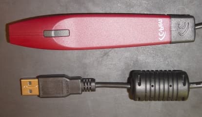
Dec 15, 2001Scanning mouse
Equipment Class
JBC - Part 15 Class B Computing Device/Personal Computer