P3TBDA85S-1B3LCESMR BI-DIRECTIONAL AMPLIFIER
Fiplex Communications Inc
Click to zoom
Application Details
- Equipment Class
- TNB - Licensed Non-Broadcast Station Transmitter
- Date of Grant
- Jun 30, 2010
- Application Purpose
- Original Equipment
- Date of Application
- Jun 29, 2010
- Equipment Note
- ESMR BI-DIRECTIONAL AMPLIFIER
- Frequency Range
- 851.00000000 - 869.00000000
- Company
- Fiplex Communications Inc
- Country
- United States
Documents & Files
Document Text
Text extracted from the exhibit documents filed with the FCC. Open a document above to read the original.
Users Manual
FIPLEX • Electromagnetic Devices for Radiocommunication Systems 1 Document FIP-BDAM-07-EN FIPLEX BIDIRECTIONAL AMPLIFIER - USER MANUAL FIPLEX • Electromagnetic Devices for Radiocommunication Systems FIPLEX BIDIRECTIONAL AMPLIFIER - USER MANUAL THIS PAGE HAVE BEEN LEFT INTENTIONALY IN BLANK FIPLEX COMMUNICATIONS, INC. M.E.BRAUN-FIPLEX 7331 N.W. 54 th Street S. Cabral 1242 Miami, FL 33166 (5006) Córdoba U.S.A. Argentina Ph: (305)884-8991 Tel: (54-351)456-8263 Fax: (305)884-4041 Fax: (54-351)456-2507 E-mail: [email protected] E-mail: [email protected] 2 Document FIP-BDAM-07-EN FIPLEX • Electromagnetic Devices for Radiocommunication Systems FIPLEX BIDIRECTIONAL AMPLIFIER - USER MANUAL INDEX Technical specifications. ................................................... Page. 4 Installation Instructions. .................................................... Page. 6 Commissioning ................................................................... Page. 10 Downlink gain setup.......................................................... Page. 12 Uplink gain setup ............................................................ Page. 13 Alarms .......................................................................... Page. 16 Remote Management and Control System Remote Management and Control Module .................. Page. 17 FIPLEX BDA Local Management Software Overview................................................................ Page. 19 Installation Instructions ........................................... Page. 19 Operation .................................................................. Page. 20 BDA Information............................................................. Page. 22 BDA Status................................................................ Page. 23 BDA Configuration ................................................... Page. 24 Communication Configuration.................................... Page. 26 3 Document FIP-BDAM-07-EN FIPLEX • Electromagnetic Devices for Radiocommunication Systems FIPLEX BIDIRECTIONAL AMPLIFIER - USER MANUAL TECHNICALL SPECIFICATIONS Mechanical dimensions CABINET A1 Drill pattern for mounting 4 Document FIP-BDAM-07-EN FIPLEX • Electromagnetic Devices for Radiocommunication Systems FIPLEX BIDIRECTIONAL AMPLIFIER - USER MANUAL CABINET B1 Drill pattern for mounting 5 Document FIP-BDAM-07-EN FIPLEX • Electromagnetic Devices for Radiocommunication Systems FIPLEX BIDIRECTIONAL AMPLIFIER - USER MANUAL INSTALLATION INSTRUCTIONS Mounting considerations. BDA is provided in a closed cabinet, with six fixing holes for wall mounting (Mounting brackets are not provided with BDA). BDA should be mounted with input/output connectors facing down in order to preserve water tightness. Roof Wall Floor 6 Document FIP-BDAM-07-EN FIPLEX • Electromagnetic Devices for Radiocommunication Systems FIPLEX BIDIRECTIONAL AMPLIFIER - USER MANUAL Natural convection flow should be guaranteed trough heat dissipator in order to keep repeater temperature between safety margins ( -30°C to +60°C). Keep minimum distance of 15 cm between heat dissipator and any object that could avoid free airflow circulation. Cold air Hot air Safety Any personnel involved in installation, operation or service of Fiplex repeaters must understand and obey the following: Repeaters are designed to receive and amplify signals from one or more base stations and retransmit the signals to one or more mobile stations, and vice versa. The repeaters must be used exclusively for these purposes and nothing else • Repeaters supplied from AC voltage must be connected to ground to guarantee safety operational conditions and to preserve the equipment. • Repeaters generate radio signals and thereby give rise to electromagnetic fields that could be hazardous to the health of any person who is extensively exposed to the signals at the immediate proximity of the repeater antennas. Coaxial cables insulation is made of polytetrafluoro ethylene, that could gives off small quantities of hydrogen fluoride when heated. Hydrogen fluoride is poisonous. Do not use heating tools when stripping coaxial cables insulation. 7 Document FIP-BDAM-07-EN FIPLEX • Electromagnetic Devices for Radiocommunication Systems FIPLEX BIDIRECTIONAL AMPLIFIER - USER MANUAL AC Power THE POWER SUPPLY UNIT CONTAINS DANGEROUS VOLTAGE THAT CAN CAUSE ELECTRIC SHOCK. DISCONNECT THE MAINS PRIOR TO ANY WORK IN THE REPEATER. AUTHORIZED SERVICE PERSONNEL ONLY ARE ALLOWED TO SERVICE REPEATERS WHILE THE MAINS IS CONNECTED. Mains should be 110-220 VAC 50-60 Hz with ground terminal connection (yellow and green cable). A good ground connection must be done in order to preserve the equipment and system reliability. A 2 Amps fuse (5 x 20mm) is used as power supply protection against severe failure in mains power. DANGER ALWAYS REMOVE MAINS POWER BEFORE CHECKING OR CHANGING FUSES. 120 VAC CAN BE LETHAL. DC Power There is an alternative way to power the repeater, this is by means of a DC power source. DC power must be feed to the repeater main board by means of a specific connector (please see figure below). Accessing the repeater from the outside with the DC power cord must be done through the cable gland labeled “BATERY BACKUP”. Nominal DC voltage is specified in the repeater datasheet specifications. When DC voltage goes under the 80% of the nominal voltage, system will be in BATTERY FAIL status. 8 Document FIP-BDAM-07-EN FIPLEX • Electromagnetic Devices for Radiocommunication Systems FIPLEX BIDIRECTIONAL AMPLIFIER - USER MANUAL Power connectors – Check polarity before connect In the presence of AC power, the system switchs automatically from DC power to AC power in order to preserve battery charge. Battery backup system is not provided with the repeater, nominal voltages and currents should be observed in order to prevent from malfunction. See specification sheet. For further assistance please contact factory. VERIFY THAT CABLE GLAND IS WELL FITTED IN ORDER TO PRESERVE WHEATER TIGHTNESS OF…
Text truncated - open the document above for the full version.
Block Diagram
LNA DOWNLINK UPLINK POWER SUPPLY UNIT ATTENUATION AND ALARM MODULE LNA AGC TO BASE TO MOBILES ISOLATION CONTROL AGC PA EXTRA GAIN / AGC OFF MAINS INPUT VSWR DET DL ATT UL ATT BDA85S-1B3LC BLOCK DIAGRAM ALARMS SYSTEM OKAMP.DL FAILAMP.UP FAILBATTERY FAIL FAILURE ALARMISOLATION CONTROLPOWER FAILTEMPERATURE DOWNLINK GAIN ADJ. UPLINK GAIN ADJ.
Cover Letter(s)
COMMUNICATIONS, INC. Electromagnetic Devices for Radio Communications Systems Fiplex Communications Inc. hereby authorizes Timco Engineering Inc. to act on our behalf before Federal Communications Commission in matters concerning equipment authorization. Any and all acts carried out by Timco Engineering, Inc. shall have the same effect as acts of our own. Further, Fiplex Communications Inc. certifies that no party to the application is subject to a denial of federal benefits, that includes FCC benefits, pursuant to Section 301 for the Anti-Drug Abuse Act of 1988, 21 U.S.C. 853(a). For the definition of a “party” for these purposes, see 47 CFR 1.2002 (b). This authorization expires one year the date of this letter. Dated: April 27, 2010____________ By: __________________________ __RICARDO DE GOYCOECHEA (signed) (printed) Title: CEO ________ Ph # in USA: 305 884 8991____ 7331 N.W. 54 th Street, Miami, Florida 33166 Phone: (305)884-8991 . Fax: (305)884-4041 . E-mail: [email protected]
Cover Letter(s)
COMMUNICATIONS, INC. Electromagnetic Devices for Radio Communications Systems April 27, 2010 Subject: Request for Confidentiality FCCID: P3TBDA85S-1B3LC Gentlemen: In reference to Section 0.457(d) of the Commission’s Rules, and Section 552(b)(4) of the Freedom of Information Act, Fiplex Communications, Inc. is requesting withholding from public information all schematics and part lists. The request for confidentiality is due to a very competitive market and necessity to keep proprietary design by Fiplex Communications, Inc. intact. The requested schematics and part lists will be submitted in a package labeled as “Confidential”. Ricardo de Goycoechea. CEO Fiplex Communications Inc. CC: Sharon Hoffman Timco Engineering, Inc. 849 NW State Road 45 Newberry, Florida 32669 7331 N.W. 54 th Street, Miami, Florida 33166 Phone: (305)884-8991 . Fax: (305)884-4041 . E-mail: [email protected]
External Photos
EXTERNAL PHOTOS BDA85S-1B3LC PAGE 1/6 FRONT VIEW EXTERNAL PHOTOS BDA85S-1B3LC PAGE 2/6 BOTTOM VIEW EXTERNAL PHOTOS BDA85S-1B3LC PAGE 3/6 TOP VIEW EXTERNAL PHOTOS BDA85S-1B3LC PAGE 4/6 BACK VIEW EXTERNAL PHOTOS BDA85S-1B3LC PAGE 5/6 RIGHT VIEW EXTERNAL PHOTOS BDA85S-1B3LC PAGE 6/6 LEFT VIEW
ID Label/Location Info
TO BASE WARNING: Total input powermust not exceed -15dBm,permanent damage may occur.ADVERTENCIA: La potenciatotal de entrada no puedesuperar -15dBm, se puedegenerar daño permanente. AC POWER INPUT 110 / 220 VAC 50/60 Hz BACKUP BATTERY INPUT TO MOBILE DRAWING Nro: REF: FCC ID LABEL LOCATION DRAWING BY: MDGDATE: 04/27/10MATERIAL: POLYESTER LABELESCALE: NOT TO SCALE PAGE: 1 / 1 10042701 Rev B
ID Label/Location Info
COMMUNICATIONS, INC. Electromagnetic Devices for Radio Communications Systems 7331 N.W. 54 th Street, Miami, Florida 33166 Phone: (305)884-8991 . Fax: (305)884-4041 . E-mail: [email protected]
Internal Photos
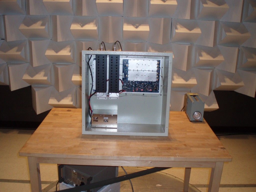
INTERNAL PHOTOS BDA85S-1B3LC 1/5 INTERNAL PHOTOS BDA85S-1B3LC 2/5 INTERNAL PHOTOS BDA85S-1B3LC 3/5 INTERNAL PHOTOS BDA85S-1B3LC 4/5 INTERNAL PHOTOS BDA85S-1B3LC 5/5
Operational Description
BIDIRECTIONAL AMPLIFIER ESMR BAND BDA85S-1B3LC Repetidor de canal selectivo Compact Repeater Model : BDA85S-1B3LC The BDA85S-1B3LC is a repeater designed for high power applications. With an excellent cost benefit ratio this repeater brings unbeatable performance filtering and signal quality. Physical dimensions: MECHANICAL SPECIFICATIONS RF Connectors N female Cabinet type FIPLEX B1 Dimensions ( height x width x length.), mm 535 x 595 x 256 (mm) Cabinet Closed cabinet, with screws Mounting Six holes for wall mount. Power supply : AC Power supply: 110 - 220 Vac 50-60Hz @ 2.5A UPS Fiplex: UPS - 500L / T-01 (optional) Recommended Battery for UPS: BOSCH SILVER 100BSE 12Vdc@100Ah. Repeater Specifications Compact Repeater ELECTRIC SPECIFICATIONS Type: Compact Repeater Frequency Band ESMR Band pass frequencies, in MHz(*) Uplink Downlink 806 – 824 MHz 851 – 869 MHz Band Width 18 MHz Number of adjustable filters NO Gain, without attenuation, Typ. Uplink Downlink 80 dB 80 dB Gain Ripple +/- 1.5dB max Manual attenuation range. Yes, 25dB in 1dB steps UL and DL independent. AGC range. Yes, 20dB range UL y DL independent. Overload protection Yes Maximum output power Uplink Downlink +27 dBm +37 dBm Maximum input power Uplink Downlink -10 dBm -10 dBm OIP3 Uplink Downlink > 45 dBm > 57 dBm Noise Figure <6dB Return Loss (both ports) 1.4: 1 max (15dB min) Group delay (worst case) 1uS max. Nominal Impedance (all ports) 50 Ω Temperature Range, (°C) -30 a +60 °C Local Alarms Yes – Light indicators Local Connectivity (Optional)– RS232 BDA Local Management Software Remote Connectivity (Optional) MODEM wireless FIPLEX BDA Local Management Software MTBF 50.000 hours min Cabinet type IP65 Repeater Specifications
Parts List/Tune Up Info
COMMUNICATIONS, INC. Electromagnetic Devices for Radio Communications Systems 7331 N.W. 54 th Street, Miami, Florida 33166 Phone: (305)884-8991 . Fax: (305)884-4041 . E-mail: [email protected] The unit is factory aligned and calibrated at the time of manufacture. It is designed to retain this calibration for the life of the product. Because of this manufacture process, there is no field tune-up or alignment necessary.
RF Exposure Info
6/15/2010 Page 1 of 3 FCCID: P3TBDA85S-1B3LC FCC RF Exposure Requirements General information: Device category: Fixed per Part 2.1091/1.1307/1.1310 Environment: Uncontrolled Exposure Fixed devices that operate under Part 90 of this chapter are subject to routine environmental evaluation for RF exposure prior to equipment authorization or use if they operate at frequencies of 1.5 GHz or below and their effective radiated power (ERP) is 1.5 watts or more. Compliance with the power density limits of 1.1310 is required. Antenna: The manufacturer does not specify an antenna. A typical fix mounted antenna has a gain of anywhere from 3 dBi to 10 dBi. This device has provisions for operation from a a fixed location. Configuration Antenna p/n Type Max. Gain (dBi) Fixed mounted Any omni or directional 3-7 Operating configuration and exposure conditions: The conducted output power is 5 Watts. Control of exposure is uncontrollable. - Part 2.1091 states that devices are excluded from routine evaluation if the EIRP is less than 2.46Watt (or 1.5WERP). - Fixed operation: A typical installation consists of an antenna system with a coaxial cable of the type RG 8U which has a loss of 2dB for a length of 30 feet at 850 MHz. frequencies. MPE Calculation: The minimum separation distance is calculated as follows: The limit for uncontrolled exposure environment above 300 MHz is f/1500 mW/cm 2 . 6/15/2010 Page 2 of 3 FCCID: P3TBDA85S-1B3LC Frequency: 850 MHz The conducted power output is 5 watt. The coax loss was taken as 2 dB. 30 ft RG-8 type. Antenna gain was taken as 7 dBi 6/15/2010 Page 3 of 3 FCCID: P3TBDA85S-1B3LC Conclusion: The device complies with the MPE requirements by providing a safe separation distance of 47 cm (1.5 ft) between the antenna, including any radiating structure, and any persons when normally operated . Proposed RF exposure safety information to include in User’s Manual: “FCC RF Exposure Requirements: See Users Manual
Test Report
INDUSTRY CANADA RSS-131 AND FCC PART 90 TEST REPORT Applicant FIPLEX COMMUNICATIONS INC. Address 7331 N.W. 54TH STREET MIAMI FL 33166 - USA FCC ID P3TBDA85S-1B3LC IC Label 8986A-BDA85S1B3LC Model Number BDA85S-1B3LC Product Description ESMR BI-DIRECTIONAL AMPLIFIER Date Sample Received 4/27/2010 Date Tested 5/3/2010 Tested By Nam Nguyen Approved By Mario de Aranzeta Report No. 968AUT10TestReport.doc Test Results PASS FAIL THE ATTACHED REPORT SHALL NOT BE REPRODUCED EXCEPT IN FULL WITHOUT THE WRITTEN APPROVAL OF TIMCO ENGINEERING, INC. Test Certificate #0955-01 849 NW STATE ROAD 45 NEWBERRY, FL 32669 USA PH: 888.472.2424 OR 352.472.5500 FAX: 352.472.2030 EMAIL: [email protected] HTTP://WWW.TIMCOENGR.COM APPLICANT: FIPLEX COMMUNICATIONS INC. FCC ID: P3TBDA85S-1B3LC, IC: 8986A-BDA85S1B3LC Repot #: F\FIPLEX_P3T\968AUT10\968AUT10TestReport.doc Page 2 of 33 TABLE OF CONTENTS ATTESTATION STATEMENT..................................................................................................... 3 REPORT SUMMARY .................................................................................................................4 TEST ENVIRONMENT .............................................................................................................. 4 TEST SETUP ............................................................................................................................ 4 DEVICE UNDER TEST INFORMATION ..................................................................................... 5 EQUIPMENT LIST .................................................................................................................... 6 TEST PROCEDURE..................................................................................................................7 RF POWER OUTPUT .............................................................................................................. 10 INPUT/OUTPUT MODULATED AMPLITUDE COMPARISON AND BAND-EDGES COMPLIANCE .............................................................................................................................................. 11 Test Data Table 3 – IDEN – Uplink/Downlink .................................................................. 12 Figure 1: IDEN – In vs. Out 806.02MHz............................................................... 12 Figure 2: IDEN – In vs. Out 823.98 MHz ............................................................. 13 Figure 3: IDEN – In vs. Out 851.02 MHz ............................................................. 14 Figure 4: IDEN – In vs. Out 868.98 MHz ............................................................. 15 Test Data Table 4 – APCO25 – Uplink/Downlink.............................................................. 16 Figure 5: APCO25 – In vs. Out 806.02 MHz ......................................................... 16 Figure 6: APCO25 – In vs. Out 823.98 MHz ......................................................... 17 Figure 7: APCO25 – In vs. Out 851.02 MHz ......................................................... 18 Figure 8: APCO25 – In vs. Out 868.98 MHz ......................................................... 19 INTERMODULATION PRODUCT SPURIOUS EMISSIONS........................................................ 20 Figure 9: IDEN 3 tones intermodulation - (806 – 824) MHz.................................. 21 Figure 10: IDEN 3 tones intermodulation - (851 - 869) MHz. ............................... 22 Figure 11: APCO25 3 tones intermodulation – (806 – 824) MHz........................... 23 Figure 12: APCO25 3 tones intermodulation - (851 – 869) MHz. .......................... 24 SPURIOUS EMISSIONS AT ANTENNA TERMINALS ................................................................ 25 Test Data Table 5 – Conducted Emissions – iDEN – Uplink .............................................. 25 Test Data Table 6 – Conducted Emissions – iDEN – Downlink.......................................... 25 Test Data Table 7 – Conducted Emissions – APCO25 – Uplink ......................................... 26 Test Data Table 8 – Conducted Emissions – APCO25 – Downlink..................................... 26 OUT OF BAND REJECTION: FREQUENCY RESPONSE .......................................................... 27 Figure 13. Frequency response (806 – 824) MHz band......................................... 27 Figure 14. Frequency response (851 – 869) MHz band......................................... 28 FIELD STRENGTH OF SPURIOUS EMISSIONS ...................................................................... 29 Test Data Table 9 – Radiated Emissions - CW .................................................................. 29 Test Data Table 10 – Radiated Emissions - CW ................................................................ 30 MEAN OUTPUT POWER FOR MULTI-CHANNEL ENHANCER (FOR IC ONLY).......................... 31 Test Data Table 11 – Mean Power .................................................................................... 31 PASSBAND GAIN AND BANDWIDTH (FOR IC ONLY) .............................................................. 32 Figure 15: Passband Gain and Bandwidth (uplink 800 MHz)............................... 32 Figure 16: Passband Gain and Bandwidth (downlink 800 MHz)........................... 33 APPLICANT: FIPLEX COMMUNICATIONS INC. FCC ID: P3TBDA85S-1B3LC, IC: 8986A-BDA85S1B3LC Repot #: F\FIPLEX_P3T\968AUT10\968AUT10TestReport.doc Page 3 of 33 ATTESTATION STATEMENT Summary The device under test does: fulfill the general approval requirements as identified in this test report not fulfill the general approval requirements as identified in this test report This equipment has been tested in accordance with the standards identified in this test report. To the best of my knowledge and belief, these tests were performed using the measurement procedures described in this report. All instrumentation and accessories used to test products for compliance to the indicated standards are calibrated …
Text truncated - open the document above for the full version.
Contact Information
Applicant
Ricardo de Goycoechea(General Manager)
Test Firm
Timco Engineering, Inc.Bruno Clavier
Technical Specifications
| # | Rule Parts | Frequency Range | Power Output | Emission | Tolerance |
|---|---|---|---|---|---|
| 6 | 9 | 851 MHz - 869 MHz | 4 W | F1E | Amp |
Other Applications from Fiplex Communications Inc

P3TDHS40-HG-2B
Dec 21, 2023800 MHz Single Carrier Amplifier (SCA) Class B
Equipment Class
B9B - Part 90 Class B Industrial Booster (non-SMR)
P3TDH14-12B
May 25, 2023Low Band FLEX Master
Equipment Class
B9B - Part 90 Class B Industrial Booster (non-SMR)
P3TDH14-10A
May 02, 2023UHF Low Band Digital Signal Booster BDA
Equipment Class
B9A - Part 90 Class A Industrial Booster (non-SMR)
P3TDH14-10B
May 02, 2023UHF Low Band Digital Signal Booster BDA
Equipment Class
B9B - Part 90 Class B Industrial Booster (non-SMR)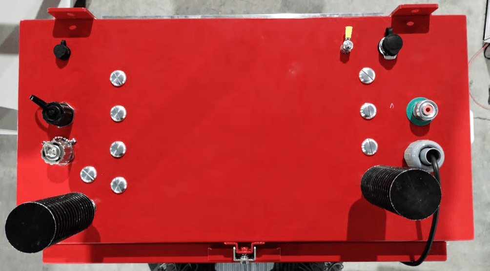
P3TDH7S-8B
Mar 26, 2023BDA All In One Digital Signal Booster
Equipment Class
B9B - Part 90 Class B Industrial Booster (non-SMR)