P4V-EASYPLUS-1Emergency Alert System
Trilithic, Inc.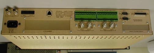
Click to zoom
Application Details
- Equipment Class
- EAD - Part 11 Emergency Alert Devices
- Date of Grant
- Jul 09, 2002
- Application Purpose
- Original Equipment
- Date of Application
- May 22, 2002
- Equipment Note
- Emergency Alert System
- Company
- Trilithic, Inc.
- Country
- United States
Documents & Files
Document Text
Text extracted from the exhibit documents filed with the FCC. Open a document above to read the original.
Users Manual
EASy-PLUS ® User Manual – 1 TRILITHIC Rev 1.02 Model EASy-PLUS ® Emergency Alert System Encoder/Decoder User’s Manual P/N 0010224001 EASy-PLUS ® User Manual 2 – TRILITHIC Rev 1.02 Trilithic Incorporated’s latest innovation for your Emergency Alert System is the EASy-PLUS ® Encoder/ Decoder. The fully featured E.A.S system, highlighted by the EASy-PLUS ® Encoder/Decoder was designed with the smallest of cable systems in mind, and can handle a system serving 100 subscribers as well as systems handling over 2,000,000 subscribers. With Trilithic’s embedded DSP technology and manufacturing, standard features such as FLASH BIOS will guarantee that your EASy-PLUS ® platform will never go out of style. Periodic updates to the platform are handled with the ease of a simple download from our WEB site. No more disassembly just to change proms or software. With Trilithic’s EASy-NET ® option, a simple phone call from your desktop PC to any one of your remote headends, allows you to retrieve the last 100 E.A.S. events from nonvolatile memory for logging and printing at your office. You’ll never miss your FCC required logging because of printer failures, paper jams or lack of paper. Innovations such as built-in AM/FM/NOAA selectable tuners, automatically generated and programmable FCC weekly testing, remote hub-site transmitter, and complete Motorola® digital platform compliance, truly makes this your Emergency Alert System of choice. The EASy-PLUS ® has the following standard and built-in, features and benefits: §EASy-PLUS ® enables parsing of F.I.P.S. codes The new Trilithic EASy-PLUS ® encoder/decoder distributes individual analog E.A.S. messages structured for, or earmarked for, one specific community or up to sixteen (16) communities located within multi-trunk output headends. §Flash BIOS Trilithic’s new EASy-PLUS ® encoder/decoder eliminates the need to remove the unit from the rack, pull the cover or lid and change or upgrade chipsets and proms. Government-regulation modifications or changes, new programming, additional advancements, and many other new features, can easily be handled through a simple upload via the WEB. §Programmable RWT (Required Weekly Test) for Automatic Triggering This feature allows your E.A.S. system to automatically generate a random RWT event, once, within each seven (7) day window, satisfying the FCC requirement for cable systems generating and logging their own weekly test. §Stores the most recent 100 emergency alerts A nonvolatile Emergency Alert Storage System eliminates the need for attaching a printer at the headends’ encoder/decoder to view the most current alerts or events. A continuous update of the last 100 E.A.S. events triggered through Trilithic’s EASy-PLUS ® encoder/decoder can be downloaded via a PC at the headend, or through the optional EASy-NET ® telephone interface anywhere in the country. E.A.S. events can easily be archived and/or printed on an external dot-matrix printer at the customer’s convenience. Logfile is word-processor compatible. §Two (2) internal radios that are each tunable as AM, FM, or NOAA radios This means you will not have to purchase any additional radios to meet the FCC requirement of LP-1 and LP-2 monitoring stations. Simply tune each of the two radio receivers to either AM or FM, to match the designated LP-1 and LP-2 stations assigned for your area, or the NOAA frequencies if so needed. Dual cards can be installed giving four (4) internal radio selections. §Four (4) external radio inputs for added monitoring capabilities This feature allows you to meet the requirements dictated by some State Emergency Management Plans that may require a possible third, fourth or more monitoring selections. §Remote hub-site insertion transmitter is included as standard equipment An internal AFSK TX transmitter is included as standard equipment in the new EASy-PLUS ® encoder/ decoder. This transmitter eliminates all external remote TX components of earlier E.A.S. systems. EASy-PLUS ® User Manual – 3 TRILITHIC Rev 1.02 The AFSK TX transmitter is self-contained, and includes audio switching capabilities for “tune-to” audio distribution and remote hub-site support via Trilithic’s Virtual Controller. §Three (3) Programmable dry-contact-closure relays These programmable relays can be conveniently used for directly driving comb generators, Motorola® OM- 1000(s) for digital E.A.S., and multi-vendors distribution switches. §Audio D/A outputs Four (4) outputs are included on the EASy-PLUS ® encoder/decoder allowing for simple audio distribution utilizing all technologies of switching. §Latest DSP Technology Trilithic’s use of Digital Signal Processing provides the most current engineering and manufacturing processes available. §EASy-Plus Setup Program The simple, user-friendly setup program walks you through the entire system setup easily, upon initializa- tion. No guess work involved. §EASy-Plus Standard Features The EASy-PLUS ® encoder/decoder has a built-in Character Generator, a Microphone for generating your own messages, front-panel Speaker, TTL control lines, front panel Keypad entry, and an Audio Distribution Amplifier. §Trilithic, Inc. is an ISO-9001 Certified company. §Trilithic, Inc., has a dedicated Marketing, Sales and Engineering in Indiana, New York and North Carolina committed solely to YOUR current E.A.S. needs and your future E.A.S. support. EASy-PLUS ® User Manual 4 – TRILITHIC Rev 1.02 CONTENTS SECTION 1 GENERAL INFORMATION..................................................................................................................................................6 1.1Introduction 1.2Specifications 1.3FCC Certification7 1.4Warranty8 1.5Claims for Damage in Shipment 1.6Technical Support SECTION 2 UNDERSTANDING THE EASy-PLUS® SYSTEM.................................................................................................................9 2.1Introduction 2.2Unpacking and Inspection 2.3Front Panel 2.4Back Panel10 2.5Terminal Connec…
Text truncated - open the document above for the full version.
Block Diagram
123456 A B C D 654321 D C B A Title NumberRevisionSize B Date:25-Jan-2002Sheet of File:E:\EASyPLUS\design\TTLboard\BLOCK.DDBDrawn By: COM1 Data COM2 Data RS-485 Data for CG / External Device control Flash Memory Data/Addressing Static Memory Data/Addressing Boot Loader Operating System EAS Data Setup Info Battery Backed Static MemoryBattery and RAM ControllerRapid Access and NV Logs To computer or other External RS-232 Device To computer or other External RS-232 Device Character Generator External External Video In Video Out handshakes(XG) handshakes(XG) Flash Control (XG) RS-485 Data Direction (XG) External External Audio In Audio Out External RS-485 RS-232 Buffers Level Converters RS-232 Buffers Level Converters Reset Control Hardware Reset Out Reset In +3.3 Volt Power Software Micro-Controller Address/Data/Control I/O Controller and Glue Logic (XG) 20x4 Alpha-Numeric Display Reference Oscillators 12.288 MHz Micro-Controller Clock 4x4 Keypad Real Time Clock 32.768Addr/Data (XG) Battery Power External PTR Port Parallel Port Buffer Audio Flash Address/Data (XG) Audio Expansion 1 (Radio or BaseBand) Audio Expansion 2 (Radio or BaseBand) I2C Control Control External Ant. IN External Ant. IN I2C DSP 24.576 MHz Reset Reset To DSP, Codecs, etc... Address/Data/Control (XG) DSP Interrupt Request RS-485 IN/OUT uProcessor/Control 14.318 MHz OSC. 7.3728 MHz OSC. Video Generation Keyer Buffer Ctrl. Font ROMs Sync Detector PLL / Dot Clock RAM/ROM Codec 0 Codec 1 wired for crosspoint data/ctrl 24.576 MHz 8KHz Anti- Alias Filter 8KHz Anti- Alias Filter 8KHz Anti- Alias Filter 8KHz Anti- Alias Filter 8KHz Anti- Alias Filter 8KHz Anti- Alias Filter Amp Front Panel Speaker and Codec 2 Amp LP Microphone External Audio CH1 External Audio CH2 V-RlyA-Rly External Audio In Audio Out External AFSK Audio Out AFSK Relay Ctrl. LP Filter AFSK Rly Full Expansion Port Microprocessor System Buss LP Filter Expansion Audio Amp External EAS Amp External EAS Amp External EAS EAS Audio EAS Audio EAS Audio Audio Out 1 Audio Out 2 Audio Out 3 Sync Serial Data (XG) Data Drvr 2 (8 chan)Data Drvr 1 (8 chan)TTL Out 1-8Out 9, 10 ExternalExternal TTL Extern CC3 Com Extern CC3 Open Extern CC3 Closed Extern CC2 Com Extern CC2 Open Extern CC2 Closed Extern CC1, Com Extern CC1 Open Extern CC1 Closed Contact Closure 1 Contact Closure 2 Contact Closure 3 External Power Power Supply 120 VAC Input To +12, -12, and 5 Volt internal active devices Legend Indicates an External Output Interface Indicates an External Input Interface Indicates an External Bi-Directional Interface (XG) Indicates that some or all signals pass through Xilinx Glue logic Devices powered by this supply line Indicates power output to multiple internal devices +12V, -12V, +5V Outputs 65KHz internal Frequency +3V and +1.5V Regulator To +3 and +1.5 Volt internal active devices Amp External EAS EAS Audio Audio Out 4 Extern CC4 Com Extern CC4 Open Extern CC4 Closed Contact Closure 4 KHz XTAL EASyPlusEncoder / Decoder Block DiagramTrilithic -
External Photos
Authorized Agent: Radiometrics Midwest Corporation (815) 293-0772 – [email protected] External EUT Photographs FCC ID: P4V-EASYPLUS-1 Photograph of Front of EUT Photograph of Back of EUT
ID Label/Location Info
FCC ID P4V-EASYPLUS-1 TRILITHICAy PLUSEAS EAS FCC ID P4V-EASYPLUS-1 TRILITHIC Ay PLUS
Internal Photos
Authorized Agent: Radiometrics Midwest Corporation (815) 293-0772 – [email protected] EUT Photographs FCC ID: P4V-EASYPLUS-1 Photograph of EUT Circuit boards; Component side Photograph of EUT Circuit Boards; Foil side Authorized Agent: Radiometrics Midwest Corporation (815) 293-0772 – [email protected] Photographs of EUT Circuit Board Component side Foil Side Authorized Agent: Radiometrics Midwest Corporation (815) 293-0772 – [email protected] Photograph of EUT ; Cover Removed
Operational Description
T rilithic EAS Encoder/Decoder test report 1 EAS Encoder/Decoder Functional Description EasyPlus, Model EASyPLUS-1 Product Detail: FCC ID: P4V-EASYPLUS-1 Equipment type: EAS Encoder/Decoder T rilithic Inc. 9710 Park Davis Drive Indianapolis, IN 46235 Phone: (317) 895-3600 Related Documents: EASyPLUS block diagram (diagram number EASBlock007) T rilithic EAS Encoder/Decoder test report 2 Table of Contents 1 General description...................................................................................................................................... 3 2 Interface..................................................................................................................................................... 4 3 Block Descriptions....................................................................................................................................... 6 4 Power up Sequence..................................................................................................................................... 8 5 Standby Operation....................................................................................................................................... 8 6 Common Sequences.................................................................................................................................... 9 T rilithic EAS Encoder/Decoder test report 3 1 GENERAL DESCRIPTION. The Trilithic EASyPLUS (PN: 2010909300) EAS (Emergency Alert System) Encoder/Decoder is a two-U rack mounted control center capable of performing manual or automated EAS messaging for Cable Headends and Hub sites, in accordance with CFR 47 part 11 FCC regulations, and the EAS Cable Handbook. The EASyPLUS receives EAS messages from up to six audio sources (internal or external), decodes the message, and operates Cable System equipment to replay the message for subscribers. In addition, messages can be originated by the user via local or remote control of the EASyPLUS. The EAS Audio sources for the EASyPLUS include internal AM/FM/NOAA radios and external audio inputs that can be connected to any known EAS audio source. EAS Audio is decoded by the internal AFSK circuitry, it is then sorted and interpreted to determine the type of emergency or test, locations for which the emergency applies, and other information supplied in the EAS Header. If a voice message is contained in the EAS message, it is recorded for possible playback to subscribers. EAS messages then pass through a series of tests to determine if the message matches predefined, user configurable parameters. If these tests pass, EAS activation of the Cable system automatically occurs. To play an EAS message to subscribers, the EASyPLUS activates TTLs and Contact Closures, as well as sending commands via RS-485 and High Data Rate AFSK, it also supplies pertinent video and re-encodes/plays the EAS FSK and recorded audio. The TTLs, Contact Closures, and RS-485 commands activate routing equipment throughout the headend to provide the emergency audio and video to all channels of the cable system. In addition to the EAS messaging capabilities, the EASyPLUS logs all received and transmitted messages to a printer, the LCD display, and it’s internal log storage area. T rilithic EAS Encoder/Decoder test report 4 2 INTERFACE Front Panel Display: The display provides visual feedback to the user during programming, setup, monitoring, and activation of the EASyPLUS. Front Panel Keypad: The keypad is used for local, real-time control of the EASyPLUS. It provides access to EAS setup and monitoring functions, as well as message encoding functions. The keypad also provides password protection for sensitive functions. Front Panel Speaker: The speaker is used for monitoring audio inputs, and to provide feedback to the user during non-messaging functions, and allows the user to hear incoming or outgoing messages during EAS activations. Front Panel Microphone: The Microphone allows the user to record EAS audio messages prior to sending, speak a “live” EAS audio message onto a cable system, or record a “Tune To” audio message used to direct subscribers to a details channel. Rear Panel: Power Entry: a single phase AC Line input with ground connection, normally powered by 117 VAC 60 Hz. CG Video In: a connection with which a cable system may supply “normal” video to a channel designated for EAS messaging. This video is replaced by the EASyPLUS during messaging. CG Video Out: provides EAS information video during messaging. This video is distributed to all cable channels during messaging, otherwise it contains the CG Video In signal. Audio Sw itch In: provides a balanced input with which a cable system may supply “normal” audio to a channel designated for EAS messaging. This audio is replaced by the EASyPLUS during messaging. Audio Sw itch Out: provides EAS information audio during messaging. This audio is distributed to all cable channels during messaging, otherwise it contains the Audio Switch In signal. RS-485 Data: provides a balanced serial data output to control peripheral devices during EAS messages. The EASyPLUS uses a 1/8 th load RS-485 to allow connection of up to 255 external devices. RS-485 data is terminated at the last device in the chain, using a 120 Ohm resistor. Audio Expansion, Audio 3, 4, 5, and 6: The audio expansions provide a means for external audio or radio tuner modules to be inserted, providing up to 6 EAS audio inputs. With a radio module attached, a 75 Ohm “F” connector is provided allowing input of AM, FM, or NOAA band signals. COM-1, COM-2: Provide an RS-232 compliant serial data connection to allow control of the EASyPLUS from an external computer, and to provide streaming EAS information to and from the EASyPLUS as required by CFR 47 part 11 for encoders and decoders. Parallel port: The parallel port provides an external printer to be connected for EAS logging purposes as required by CFR 47 part 11 for encoders and decoders. Audio Inp…
Text truncated - open the document above for the full version.
Schematics
12345678 A B C D E F G H 12345678 D E F G H J K THIS PRINT INCLUDING THE PRINCIPAL OF DESIGN IS THE PROPERTY OF AND SUBMITTED BY TRILITHIC,INC WITH THE UNDERSTANDING THAT IT IS NOT TO BE USED FOR ANY PURPOSE WITHOUT WRITTEN CONSENT OF TRILITHIC, INC AUTHORIZED PERSONNEL. DR APPD SIGNATURESDATE SIZECAGEDRAWING NO. 23042 DO NOT SCALE DRAWINGSCALE :NONESHEETOF SCHEMATIC REV TRILITHIC, INC INDIANAPOLIS, IND J K 91011 9 10 11 A B C H8_A[0..23] H8_A19 H8_D7 H8_A21 H8_A23 H8_A16 H8_A6 H8_D15 H8_D0 H8_A17 H8_A15 H8_D13 H8_D6 H8_D[8..15] H8_A7 H8_A1 H8_A0 H8_D10 H8_D4 H8_D3 H8_A18 H8_A14 H8_A5 H8_D5 H8_D1 H8_A20 H8_A12 H8_A3 H8_D8 H8_D2 H8_D12 H8_A11 H8_A9 H8_A4 H8_A8 H8_A2 H8_D14 H8_D[0..7] H8_A10 H8_D11 H8_A22 H8_A13 H8_D9 L1 470UH/5% C1 0.1U/5% SW1 PB C2 0.1U/5% C3 0.1U/5% RESET 1 GND 2 MR 3 WDI 4 VCC 5 U1 TSP3828-50 + C77 10U/10% VCC 1 PB[0]/CS7/TMO0/TP8 2 PB[1]/CS6/DREQ0/TMIO0/TP9 3 PB[2]/CS5/TMO2/TP10 4 PB[3]/CS4/DREQ1/TMIO3/TP11 5 PB[4]/UCAS/TP12 6 PB[5]/SCK2/LCAS/TP13 7 PB[6]/TxD2/TP14 8 PB[7]/RxD2/TP15 9 RESO 10 VSS 11 P9[0]/TxD0 12 P9[1]/TxD1 13 P9[2]/RxD0 14 P9[3]/RxD1 15 P9[4]/IRQ4/SCK0 16 P9[5]/IRQ5/SCK1 17 P4[0]/D0 18 P4[1]/D1 19 P4[2]/D2 20 P4[3]/D3 21 VSS 22 P4[4]/D4 23 P4[5]/D5 24 P4[6]/D6 25 P4[7]/D7 26 D8 27 D9 28 D10 29 D11 30 D12 31 D13 32 D14 33 D15 34 VCC 35 A0 36 A1 37 A2 38 A3 39 A4 40 A5 41 A6 42 A7 43 VSS 44 A8 45 A9 46 A10 47 A11 48 A12 49 A13 50 A14 51 A15 52 A16 53 A17 54 A18 55 A19 56 VSS 57 P6[0]/WAIT 58 P6[1]/BREQ 59 P6[2]/BACK 60 P6[7]/CLK 61 STBY 62 RES 63 NMI 64 VSS 65 EXTAL 66 XTAL 67 VCC 68 AS 69 RD 70 UWR 71 LWR 72 MD0 73 MD1 74 MD2 75 AVCC 76 VREF 77 P7[0]/AN0 78 P7[1]/AN1 79 P7[2]/AN2 80 P7[3]/AN3 81 P7[4]/AN4 82 P7[5]/AN5 83 P7[6]/AN6/DA0 84 P7[7]/AN6/DA1 85 AVSS 86 P8[0]/IRQ0/RFSH 87 P8[1]/IRQ1/CS3 88 P8[2]/IRQ2/CS2 89 P8[3]/IRQ3/CS1/ADTRG 90 P8[4]/CS0 91 VSS 92 PA[0]/TP0/TCLKA/TEND0 93 PA[1]/TP1/TCLKB/TEND1 94 PA[2]/TP2/TIOCA0/TCLKC 95 PA[3]/TP3/TIOCB0/TCLKD 96 PA[4]/TP4/TIOCA1/A23 97 PA[5]/TP5/TIOCB1/A22 98 PA[6]/TP6/TIOCA2/A21 99 PA[7]/TP7/TIOCB2/A20 100 U2 HD6413007 C4 0.1U/5% H8_D[8..15] H8_D[0..7] COM1_RxD COM2_RxD COM3_RxD DSP_IRQX IO_IRQ1 RTC_IRQ RF1_METER RF2_METER H8_CLK COM1_TxD COM2_TxD COM3_TxD SYSTEM_RESET H8_A[0..23] H8_UWR H8_WAIT H8_LWR H8_RD DPOT_CS DPOT_INC DPOT_U/D +3.3V +3.3V +3.3V +3.3V +5V Manual RESET H8_A8 H8_A14 H8_D11 H8_A16 H8_A9 H8_A6 H8_A3 H8_A4 H8_A7 H8_A11 H8_D10 H8_A14 H8_A1 H8_A12 H8_A13 H8_A5 H8_D9 H8_D13 H8_A8 H8_A15 H8_A19 H8_A11 H8_D14 H8_A3 H8_D0H8_A2 H8_D2 H8_D5 H8_A4 H8_D7 H8_A15 H8_D15 H8_A17 H8_A2 H8_A16 H8_A10 H8_D[0..7] H8_D12 H8_A5 H8_D4 H8_A1 H8_D6 H8_D1 H8_A17 H8_A9 H8_D3 H8_A6 H8_A13 H8_A18 H8_D[8..15] H8_D8 H8_A12 H8_A7 H8_A10 H8_A[0..23] H8_A18 H8_A19 A17 1 A16 2 A14 3 A12 4 A7 5 A6 6 A5 7 A4 8 A3 9 A2 10 A1 11 A0 12 I/O0 13 I/O1 14 I/O2 15 GND 16 I/O3 17 I/O4 18 I/O5 19 I/O6 20 I/O7 21 CE 22 A10 23 OE 24 A11 25 A9 26 A8 27 A13 28 WE 29 CE2[A18] 30 A15 31 VCC 32 U3 CY62128V C5 0.1U/5% A17 1 A16 2 A14 3 A12 4 A7 5 A6 6 A5 7 A4 8 A3 9 A2 10 A1 11 A0 12 I/O0 13 I/O1 14 I/O2 15 GND 16 I/O3 17 I/O4 18 I/O5 19 I/O6 20 I/O7 21 CE 22 A10 23 OE 24 A11 25 A9 26 A8 27 A13 28 WE 29 CE2[A18] 30 A15 31 VCC 32 U4 CY62128V C6 0.1U/5% H8_D[0..7] H8_D[8..15] H8_A[0..23] SRAM_CS H8_RD H8_LWR H8_UWR SRAM = 128K x 8 (x2) or 512k x 8 (x2) SRAM Total = 256K or 1Meg CY62128VL orCY62128VL or H8_A7 H8_D15 H8_D10 H8_D9 H8_A18 H8_A16 H8_A12 H8_A3 H8_D12 H8_A15 H8_A14 H8_A11 H8_D11 H8_A17 H8_A10 H8_A5 H8_A6 H8_A4 H8_A2 H8_A1 H8_D13 H8_A9 H8_D14 H8_D8 H8_A19 H8_A13 H8_D[8..15] H8_A8 H8_A[0..23] H8_D0 H8_D4 H8_D3 H8_D5 H8_D6 H8_D1 H8_D2 H8_D[0..7] H8_D7 R12 2K/5% FLASH MEMORY A0 25 A1 24 A2 23 A3 22 A4 21 A5 20 A6 19 A7 18 A8 8 A9 7 A10 6 A11 5 A12 4 A13 3 A14 2 A15 1 A16 48 A17 17 A18 16 A19[32m] 9 D0 29 D1 31 D2 33 D3 35 D4 38 D5 40 D6 42 D7 44 D8 30 D9 32 D10 34 D11 36 D12 39 D13 41 D14 43 D15 45 CS 26 OE 28 WR 11 RP 12 RY/BY[A19 16m] 15 BYTE 47 Vpp 13 VSS 27 VSS 46 A20[32m] 10 Vcc 37 WP 14 U6 LHF28F160 C7 0.1U/5% C9 0.1U/5% R9 3.3K/5% H8_A[0..23] FLASH_32M_SEL FLASH_16M_SEL FLASH_WP SYSTEM_RESET FLASH_WR H8_RD FLASH_CS H8_D[0..7] H8_D[8..15] +3.3V +3.3V +3.3V Expansion Port1 SRAM_CS H8_RD H8_LWR H8_UWR * FLASH SUPPORT PIN 9 PIN 10 PIN15 8 MEG BIT = NC NC READY/BUSY 16 MEG BIT= NC NC A20 32 MEG BIT= A20 A21 READY/BUSY 64 MEG BIT= A22 2M BANK A20 LPT_PD[0..7] H8_A1 H8_D13 H8_D10 H8_D[8..15] H8_A0 H8_D8 H8_D14 H8_D11 H8_A2 H8_D15 H8_D9 H8_D12 H8_A[0..23] LPT_PD0 LPT_PD1 LPT_PD2 LPT_PD3 LPT_PD4 LPT_PD5 LPT_PD6 LPT_PD7 H8_A3 KEYPAD_IN1 KEYPAD_IN3 KEYPAD_OUT0 KEYPAD_OUT3 KEYPAD_OUT2 KEYPAD_OUT1 KEYPAD_IN2 KEYPAD_IN0 H8_A4 H8_A20 C10 0.1U/5% C11 0.1U/5% C12 0.1U/5% C13 0.1U/5% C14 0.1U/5% I/O/GSR 143 I/O/GTS3 2 I/O/GTS4 3 I/O/GTS1 5 I/O/GTS2 6 I/O 9 I/O 10 I/O 11 I/O 12 I/O 13 I/O 14 I/O 15 I/O 16 I/O 17 I/O 19 I/O 20 I/O 21 I/O 22 I/O/GCK1 30 I/O/GCK2 32 I/O 26 I/O 27 I/O/GCK3 38 I/O 31 I/O 34 I/O 39 I/O 41 I/O 43 I/O 44 I/O 45 I/O 48 I/O 51 I/O 52 I/O 54 I/O 56 I/O 57 I/O 58 I/O 60 I/O 61 I/O 66 I/O 68 I/O 69 I/O 70 I/O 74 I/O 75 I/O 76 I/O 78 I/O 79 I/O 80 I/O 81 I/O 82 I/O 83 I/O 87 I/O 88 I/O 91 I/O 92 I/O 93 I/O 94 I/O 95 I/O 96 I/O 97 I/O 98 I/O 100 TCK 67 TDI 63 TDO 122 TMS 65 VCCINT 8 VCCINT 42 VCCINT 84 VCCIO 1 VCCIO 37 VCCIO 55 VCCIO 73 GND 18 GND 29 GND 36 GND 47 GND 62 GND 72 GND 89 GND 90 VCCINT 141 VCCIO 109 VCCIO 127 GND 99 GND 108 GND 114 GND 123 GND 144 I/O 4 I/O 7 I/O 23 I/O 24 I/O 25 I/O 28 I/O 33 I/O 35 I/O 40 I/O 46 I/O 49 I/O 50 I/O 53 I/O 59 I/O 64 I/O 71 I/O 77 I/O 85 I/O 86 I/O 101 I/O 102 I/O 103 I/O 104 I/O 105 I/O 107 I/O 106 I/O 110 I/O 111 I/O 112 I/O 113 I/O 115 I/O 116 I/O 119 I/O 120 I/O 121 I/O 117 I/O 124 I/O 125 I/O 118 I/O 126 I/O 128 I/O 129 I/O 130 I/O 131 I/O 132 I/O 133 I/O 134 I/O 135 I/O 136 I/O 137 I/O 138 I/O 139 I/O 140 I/O 142 U7 XC95288XL C15 0.1U/5% C16 0.1U/5% SYSTEM_RESET H8_D[8..15] H8_A[0..23] LPT_PD[0..7] LPT_MODE LPT_DIR LPT_STROBE LPT_AUTOLF LPT_INZ LPT_SELPRT LPT_ERROR LPT_ACK LPT_PRTSEL LPT_BUSY LPT_PE H8_RD H8_UWR H8_CLK0 EX_BUS_CS COM3_DIR COM2_DSR COM1_DCD COM2_CTS COM1_RI COM…
Text truncated - open the document above for the full version.
Test Report
Radiometrics Midwest CorporationPage 1 of 20 Electromagnetic Compatibility Test Report Tests Performed on a Trilithic Emergency Alert System, Model EASyPLUS-1 Radiometrics Document RP-4700 Product Detail: FCC ID: P4V-EASYPLUS-1 Equipment type: EAD Emergency Alert Device Test Standards: US CFR Title 47, Chapter I, FCC Part 15 Subpart B FCC Part 15 CFR Title 47: 2001 This report concerns: Original Grant for Certification FCC Parts 11.32(d) and 15 Subpart B Tests Performed For:Test Facility: T rilithic 9202 East 33rd. ST. Indianapolis, IN 46235 Radiometrics Midw est Corporation 12 East Devonwood Romeoville, IL 60446 Phone: (815) 293-0772 e-mail: [email protected] Test Date(s): (Month-Day-Year) 3/4/02 and 3/22/02 Document RP-4700 Revisions: Rev.Issue DateAffected PagesRevised ByAuthorized Signature for Revision 0May 21, 2002 RADIOMETRICS MIDWEST CORPORATION - EMC Test Report Equipment Tested (Company, Model, Product Name):Document No.:Page: Trilithic, EASyPLUS-1, Emergency Alert System RP-4700 Rev. 0 2 of 19 Table of Contents 1 ADMINISTRATIVE DATA...................................................................................................................... 3 2 TEST SUMMARY AND RESULTS ....................................................................................................... 3 3 EQUIPMENT UNDER TEST (EUT) DETAILS...................................................................................... 4 3.1 EUT Description............................................................................................................................... 4 3.2 Related Submittals ........................................................................................................................... 4 4 TESTED SYSTEM DETAILS ................................................................................................................ 4 4.1 Tested System Configuration .......................................................................................................... 4 4.2 Operating mode ............................................................................................................................... 5 4.3 Special Accessories......................................................................................................................... 5 4.4 Equipment Modifications.................................................................................................................. 5 5 TEST SPECIFICATIONS AND RELATED DOCUMENTS.................................................................. 6 6 RADIOMETRICS’ TEST FACILITIES ................................................................................................... 6 7 DEVIATIONS AND EXCLUSIONS FROM THE TEST SPECIFICATIONS......................................... 7 8 TEST PROCEDURES........................................................................................................................... 7 8.1 Radiated RF Emissions Measurement Procedures ......................................................................... 7 8.1.1 Field Strength Calculation .......................................................................................................... 8 8.1.2 Conducted Emission Measurement Procedures ....................................................................... 8 9 CERTIFICATION.................................................................................................................................... 8 10 TEST EQUIPMENT TABLE ................................................................................................................ 9 11 TEST SETUP DOCUMENTATION ................................................................................................... 10 Figure 1. Configuration of RF Emissions Tests ............................................................................... 10 12 DETAILED TEST RESULTS ............................................................................................................. 11 12.1 Radiated Emissions Test Results ................................................................................................ 11 12.2 AC Conducted Emission Test Results .........................................................................................12 12.3 Antenna Conducted Test Results ............................................................................................12-18 12.3.1 Radiated RF Immunity Test Results ...................................................................................... 19 Notice: This report must not be reproduced (except in full) without the written approval of Radiometrics Midwest Corporation. RADIOMETRICS MIDWEST CORPORATION - EMC Test Report Equipment Tested (Company, Model, Product Name):Document No.:Page: Trilithic, EASyPLUS-1, Emergency Alert System RP-4700 Rev. 0 3 of 19 1 ADMINISTRATIVE DATA Equipment Under Test: A Trilithic, Emergency Alert System Model: EASyPLUS-1 Serial Number: 10001 This will be referred to as the EUT in this Report Date EUT Received at Radiometrics: (Month-Day-Year)Test Date(s): (Month-Day-Year) 2-14-022/14/02 and 3/22/02 Test Report Written By:Test Witnessed By: Joseph Strzelecki Senior EMC Engineer Allan Studer Trilithic Radiometrics’ Personnel Responsible for Test:Test Report Approved By Joseph Strzelecki Senior EMC Engineer NARTE EMC-000877-NE Chris W. Carlson Director of Engineering NARTE EMC-000921-NE 2 TEST SUMMARY AND RESULTS The EUT (Equipment Under Test) is an Emergency Alert System, Model EASyPLUS-1, manufactured by Trilithic. The detailed test results are presented in a separate section. The following is a summary of the test results. Tests Results Environmental PhenomenaFrequency RangeBasic StandardTest Result RF Radiated Emissions30 – 2000 MHzFCC Part 15Pass Conducted Emissions, AC Mains0.45 - 30 MHzFCC Part 15Pass Antenna Conducted Emissions0.1 – 2000 MHzFCC Part 15Pass Broadcast frequency Immunity1 to 787 MHzFCC Part 11.32(d)Pass RADIOMETRICS …
Text truncated - open the document above for the full version.
Test Report
T rilithic EAS Encoder/Decoder test report 1 EAS Encoder/Decoder test report Tests performed on a Trilithic EasyPlus, Model EASyPLUS-1 Product Detail: FCC ID: P4V-EASYPLUS-1 Equipment type: EAS Encoder/Decoder This report concerns: Original Grant for Certification FCC Part 11.31, 11.32, 11.33 EAS Encoder/Decoder Equipment Requirements Tests Performed at:Applicant: T rilithic Inc. 9710 Park Davis Drive Indianapolis, IN 46235 Phone: (317) 895-3600 T rilithic Inc. 9710 Park Davis Drive Indianapolis, IN 46235 Phone: (317) 895-3600 Test Date(s): (Month-Day-Year) 05/17/02, 05/21/02 T rilithic EAS Encoder/Decoder test report 2 Table of Contents 1 Administrative data...................................................................................................................................... 3 2 Test summary and results............................................................................................................................ 3 2.1 Test Result Summary....................................................................................................................... 4 3 Equipment under test (eut) details................................................................................................................. 5 3.1 EUT Description...............................................................................................................................5 3.2 Related Submittals........................................................................................................................... 5 4 Tested system details.................................................................................................................................. 6 4.1 Tested System Diagram.................................................................................................................. 6 4.2 FCC Identifiers for support equipment............................................................................................. 7 4.3 Tested System Configuration.......................................................................................................... 7 4.4 Tested System Equipment List.................................................................................…
Text truncated - open the document above for the full version.
Contact Information
Applicant
Michael Andrew Maginity(EAS Engineering Manager)
Technical Contact
Radiometrics Midwest CorporationJoseph R Strzelecki
[email protected]815-293-0772
12 East Devonwood Av. · Romeoville, Illinois · United States
Non-Technical Contact
Radiometrics Midwest CorporationJoan E Strzelecki
[email protected]815-293-0772
Test Firm
Radiometrics Midwest CorporationJoseph Strzelecki
815-293-0772Fax: 815-293-0820
Technical Specifications
| # | Rule Parts | Frequency Range | Power Output |
|---|---|---|---|
| 1 | 11 | - | - |
Other Applications from Trilithic, Inc.
P4V-MCAIII
May 27, 2014Seeker MCA III Cable Installer Meter with Wi-Fi
Equipment Class
DTS - Digital Transmission System
P4V360DSP
Aug 24, 2012Cable Installer Meter with Wi-Fi
Equipment Class
DTS - Digital Transmission System
P4V-EASYCAP-1
Nov 27, 2011Emergency Alert System
Equipment Class
EAD - Part 11 Emergency Alert Devices